EXFO FTB-3930 User manual

USER GUIDE
MULTITEST MODULE
FTB-3930
NETWORK TESTING

ii FTB-3930
Copyright © 2006 EXFO Electro-Optical Engineering Inc. All rights reserved.
No part of this publication may be reproduced, stored in a retrieval system
or transmitted in any form, be it electronically, mechanically, or by any
other means such as photocopying, recording or otherwise, without the
prior written permission of EXFO Electro-Optical Engineering Inc. (EXFO).
Information provided by EXFO is believed to be accurate and reliable.
However, no responsibility is assumed by EXFO for its use nor for any
infringements of patents or other rights of third parties that may result from
its use. No license is granted by implication or otherwise under any patent
rights of EXFO.
EXFO’s Commerce And Government Entities (CAGE) code under the North
Atlantic Treaty Organization (NATO) is 0L8C3.
The information contained in this publication is subject to change without
notice.
Trademarks
EXFO’s trademarks have been identified as such. However, the presence
or absence of such identification does not affect the legal status of any
trademark.
Units of Measurement
Units of measurement in this publication conform to SI standards and
practices.
Patents
FASTESTis protected by US patent(s) 5,305,078 and/or 5,455,672.
EXFO’s Universal Interface is protected by US patent 6,612,750.
Version number: 3.1.2.7

Contents
MultiTest Module iii
Contents
Certification Information ........................................................................................................v
1 Introducing the FTB-3930 MultiTest Module .............................................. 1
Main Features .........................................................................................................................1
Typical Applications ................................................................................................................3
Conventions ............................................................................................................................4
2 Safety Information ....................................................................................... 5
Laser Safety Information (Units without VFL) ..........................................................................5
Laser Safety Information (Units with VFL) ...............................................................................6
3 Getting Started with Your MultiTest Module ............................................. 7
Inserting and Removing Test Modules ...................................................................................7
Starting the MultiTest Module Application ...........................................................................13
Exiting the Application .........................................................................................................15
4 Customizing Your MultiTest Module ......................................................... 17
5 Setting Up Your MultiTest Module ............................................................ 19
Installing the EXFO Universal Interface (EUI) .........................................................................19
Cleaning and Connecting Optical Fibers ...............................................................................20
Setting Autonaming Scheme ................................................................................................21
Setting Pass/Fail Thresholds ..................................................................................................23
6 Measuring Power or Loss .......................................................................... 27
Defining the List of Favorite Wavelengths .............................................................................28
Nulling Electrical Offsets .......................................................................................................30
Referencing Your Power Meter to a Source ...........................................................................31
Measuring Power or Loss ......................................................................................................34
7 Measuring Optical Return Loss ................................................................. 37
Performing ORL Reference and Setting ORL Zero Value ........................................................38
Performing and Saving ORL Measurements ..........................................................................40
8 Performing Automated IL/ORL/Length Measurements (FASTEST) .............. 43
Setting Up the FASTEST........................................................................................................44
Referencing Units for FASTEST..............................................................................................46
Performing the FASTEST........................................................................................................51

Contents
iv FTB-3930
9 Managing Test Results ................................................................................55
Viewing and Deleting Results ...............................................................................................55
Customizing Result Display ...................................................................................................57
Customizing and Printing Reports ........................................................................................58
10 Using a Light Source ...................................................................................61
11 Identifying Fiber Faults Visually ................................................................63
12 Communicating with Other Users .............................................................65
Sending and Receiving Text Messages ..................................................................................65
Communicating by Voice ......................................................................................................69
13 Maintenance ................................................................................................73
Cleaning Fixed Connectors ....................................................................................................74
Cleaning EUI Connectors ......................................................................................................76
Cleaning Detector Ports ........................................................................................................78
Recalibrating the Unit ...........................................................................................................79
Recycling and Disposal (Applies to European Union Only) ....................................................80
14 Troubleshooting ..........................................................................................81
Solving Common Problems ...................................................................................................81
Obtaining Online Help ..........................................................................................................84
Finding Information on the EXFO Web Site ..........................................................................84
Contacting the Technical Support Group ..............................................................................85
Transportation ......................................................................................................................86
15 Warranty ......................................................................................................87
General Information .............................................................................................................87
Liability .................................................................................................................................88
Exclusions .............................................................................................................................88
Certification ..........................................................................................................................88
Service and Repairs ...............................................................................................................89
EXFO Service Centers Worldwide ..........................................................................................90
A Technical Specifications ..............................................................................91
Index .................................................................................................................93

Certification Information
MultiTest Module v
Certification Information
F.C.C. Information
Electronic test equipment is exempt from Part 15 compliance (FCC) in
the United States. However, compliance verification tests are
systematically performed on most EXFO equipment.
Information
Electronic test equipment is subject to the EMC Directive in the European
Union. The EN61326 standard prescribes both emission and immunity
requirements for laboratory, measurement, and control equipment.
This unit has undergone extensive testing according to the European Union
Directive and Standards.
Certification Information
vi FTB-3930
Application of Council Directive(s): 73/23/EEC - The Low Voltage Directive
89/336/EEC - The EMC Directive
Manufacturer’s Name: EXFO ELECTRO-OPTICAL ENGINEERING INC.
Manufacturer’s Address: 400 Godin Avenue
Quebec, Quebec
Canada G1M 2K2
(418) 683-0211
Equipment Type/Environment: Industrial Scientific Equipment
Trade Name/Model No.: FTB-3930 MultiTest Module
Standard(s) to which Conformity is Declared:
EN 60825-1: 1994/
A2: 2001
Safety of Laser Products-Part 1: Equipment Classification, Requirement, and
User’s guide
EN 61326: 1997/ A2:
2001
Electrical Equipment for Measurement, Control and Laboratory
Use - EMC Requirements
EN 55022: 1998/ A1:
2000
Limits and methods of measurement of radio disturbance characteristics of
information technology equipment
I, the undersigned, hereby declare that the equipment specified above conforms to the above Directive and Standards.
Manufacturer
Signature:
Full Name: Stephen Bull, E. Eng
Position: Vice-President Research and Development
Address: 400 Godin Avenue Quebec, Quebec, Canada
Date: July 20, 2004
DECLARATION OF CONFORMITY
MultiTest Module 1
1 Introducing the FTB-3930
MultiTest Module
The FTB-3930 MultiTest Module integrates a power meter and light sources
with an optical return loss meter, optional talk set and visual fault locator.
Main Features
The unit features FASTEST™, EXFO’s one-touch automated measurement.
In 10 seconds, you can simultaneously test IL and ORL at up to four
wavelengths, in both directions. During the same test, the unit also
determines fiber length.
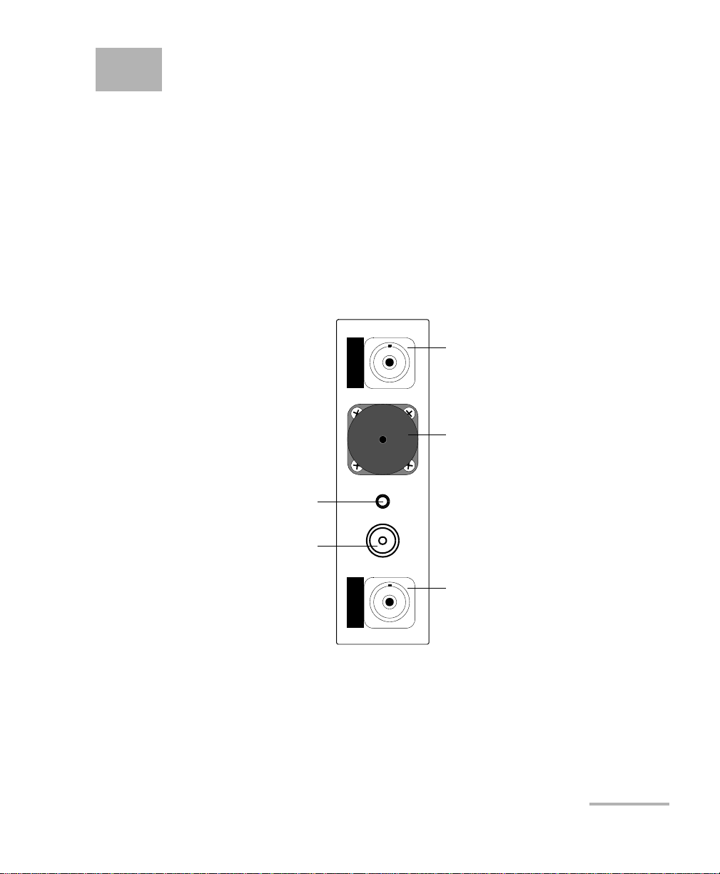
Note: Optical ports and connectors may differ from the illustration.
FTB-3930
MULTITEST
Headset connector
Power meter detector port
Visual fault locator port
Multimode port
(FASTESTand light source)
or talk set port
Singlemode port (FASTEST,
light source and ORL meter)

Introducing the FTB-3930 MultiTest Module
2FTB-3930
Main Features
The power meter has the following characteristics:
³Ge, GeX or InGaAs detector with 40 calibrated wavelengths to measure
absolute power or link loss
³Editable list of favorite wavelengths for easy access
³Modulated signal detection
³No offset nulling required in normal operation
The light source has the following characteristics:
³Singlemode port (two or three wavelengths), also used for FASTESTand
ORL.
AND/OR
Multimode port (two wavelengths), also used for FASTESTonly.
³Modulated or high-power signal compatible with other EXFO units

Introducing the FTB-3930 MultiTest Module
MultiTest Module 3
Typical Applications
Other test utilities:
³Text messaging
³Full-duplex digital talk set (optional)
³Visual fault locator to inspect or identify fibers (optional)
Result processing and analysis features (also available in the application):
³Analyze data acquired on the field using a tabular format
³Customizable test thresholds with visual pass/fail analysis
³Transfer data from the FOT-930 Multifunction Loss Tester (using the
Handheld Data Transfer application) for easier management and
greater storage capacity
³Save your OLTS data in popular text formats (XML, ASCII, etc.) or
convert older result files to the new format for analysis
³Customize user settings and cable identification parameters
³Generate and print reports about OLTS data, including user and test
location information and operator comments
³FASTESTresults displayed according to FTTx usage and terminology
Typical Applications
You can use the MultiTest Module for several applications, such as:
³Fiber installation and maintenance applications
³FTTx: testing of passive optical networks (PONs)
³Absolute power or link loss measurements
³Bidirectional loss and ORL testing
³Length measurement
³All-in-one tool for contractors
Introducing the FTB-3930 MultiTest Module
4FTB-3930
Conventions
Conventions
Before using the product described in this manual, you should understand
the following conventions:
WARNING
Indicates a potentially hazardous situation which, if not avoided,
could result in death or serious injury. Do not proceed unless you
understand and meet the required conditions.
CAUTION
Indicates a potentially hazardous situation which, if not avoided,
may result in minor or moderate injury. Do not proceed unless you
understand and meet the required conditions.
CAUTION
Indicates a potentially hazardous situation which, if not avoided,
may result in component damage. Do not proceed unless you
understand and meet the required conditions.
IMPORTANT
Refers to information about this product you should not overlook.

MultiTest Module 5
2 Safety Information
Laser Safety Information (Units without VFL)
Your instrument is a Class 1 laser or LED product in compliance with
standards IEC 60825-1 Amendment 2: 2001 and 21 CFR 1040.10.
Laser radiation may be encountered at the output port.
The following labels indicate that a product contains a Class 1 source:
Note: Labels shown for information purposes only. They are not affixed to your
product.
WARNING
Do not install or terminate fibers while a light source is active.
Never look directly into a live fiber and ensure that your eyes are
protected at all times.
WARNING
Use of controls, adjustments and procedures for operation and
maintenance other than those specified herein may result in
hazardous radiation exposure.
CLASS 1
LASER PRODUCT
CLASS 1
LED PRODUCT

Safety Information
6FTB-3930
Laser Safety Information (Units with VFL)
Laser Safety Information (Units with VFL)
Your instrument is a Class 3R laser product in compliance with standards
IEC 60825-1 Amendment 2: 2001 and 21 CFR 1040.10. It is potentially
harmful in direct intrabeam viewing.
The following label(s) indicate that the product contains a Class 3R source:
If VFL option is available
QST498C
LASER RADIATION
AVOID DIRECT EYE EXPOSURE
CLASS 3R LASER PRODUCT
IEC 60825-1:1993+A2:2001
21 CFR 1040.10
λ: 650 ±10 nm
Pout maximum < 5mW (into free space)
Affixed to
side of module
Indicated on
front panel
MultiTest Module 7
3 Getting Started with Your
MultiTest Module
Inserting and Removing Test Modules
To insert a module into the FTB-400 Universal Test System:
1. Exit ToolBox and turn off your unit.
2. Position the FTB-400 so that its right panel is facing you.
CAUTION
Never insert or remove a module while the FTB-400 Universal Test
System is turned on. This will result in immediate and irreparable
damage to both the module and unit.
WARNING
When the laser safety LED ( ) is flashing on the FTB-400, at least
one of your modules is emitting an optical signal. Please check all
modules, as it might not be the one you are currently using.
Getting Started with Your MultiTest Module
8FTB-3930
Inserting and Removing Test Modules
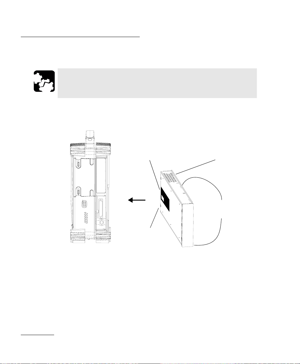
3. Take the module and place it so that the connector pins are at the
back, as explained and shown below.
³(2-slot or 4-slot receptacles) identification sticker must be on left
side and retaining screw hole under connector pins.
CAUTION
Inserting a module upside down could result in permanent damage
to the module, as the connector pins might be bent.
Protruding edges
on right side
Identification sticker
on left side Connector
pins at the
back
Retaining
screw hole
at the back
FTB-400 right panel
(2-slot receptacle)
Getting Started with Your MultiTest Module
MultiTest Module 9
Inserting and Removing Test Modules
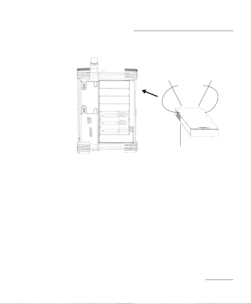
³(7-slot or 8-slot receptacles) identification sticker must be facing
down and connector pins at the left of the retaining screw hole.
4. Insert the protruding edges of the module into the grooves of the
receptacle’s module slot.
5. Push the module all the way to the back of the slot, until the retaining
screw makes contact with the receptacle casing.
6. Place the FTB-400 so that its left panel is facing you.
Protruding
edges on top
Identification sticker
facing down
Connector
pins at the
back
Retaining
screw hole
at the back
FTB-400 right panel
(7-slot receptacle)

Getting Started with Your MultiTest Module
10 FTB-3930
Inserting and Removing Test Modules
7. While applying slight pressure to the module, turn the retaining screw
clockwise until it is tightened. This will secure the module into its
“seated” position.
When you turn on the unit, the startup sequence will automatically detect
the module.
FTB-400 left panel
(2-slot or 4-slot receptacles)
Turn retaining screw knob(s)
clockwise
FTB-400 left panel
(7-slot or 8-slot receptacles)

Getting Started with Your MultiTest Module
MultiTest Module 11
Inserting and Removing Test Modules
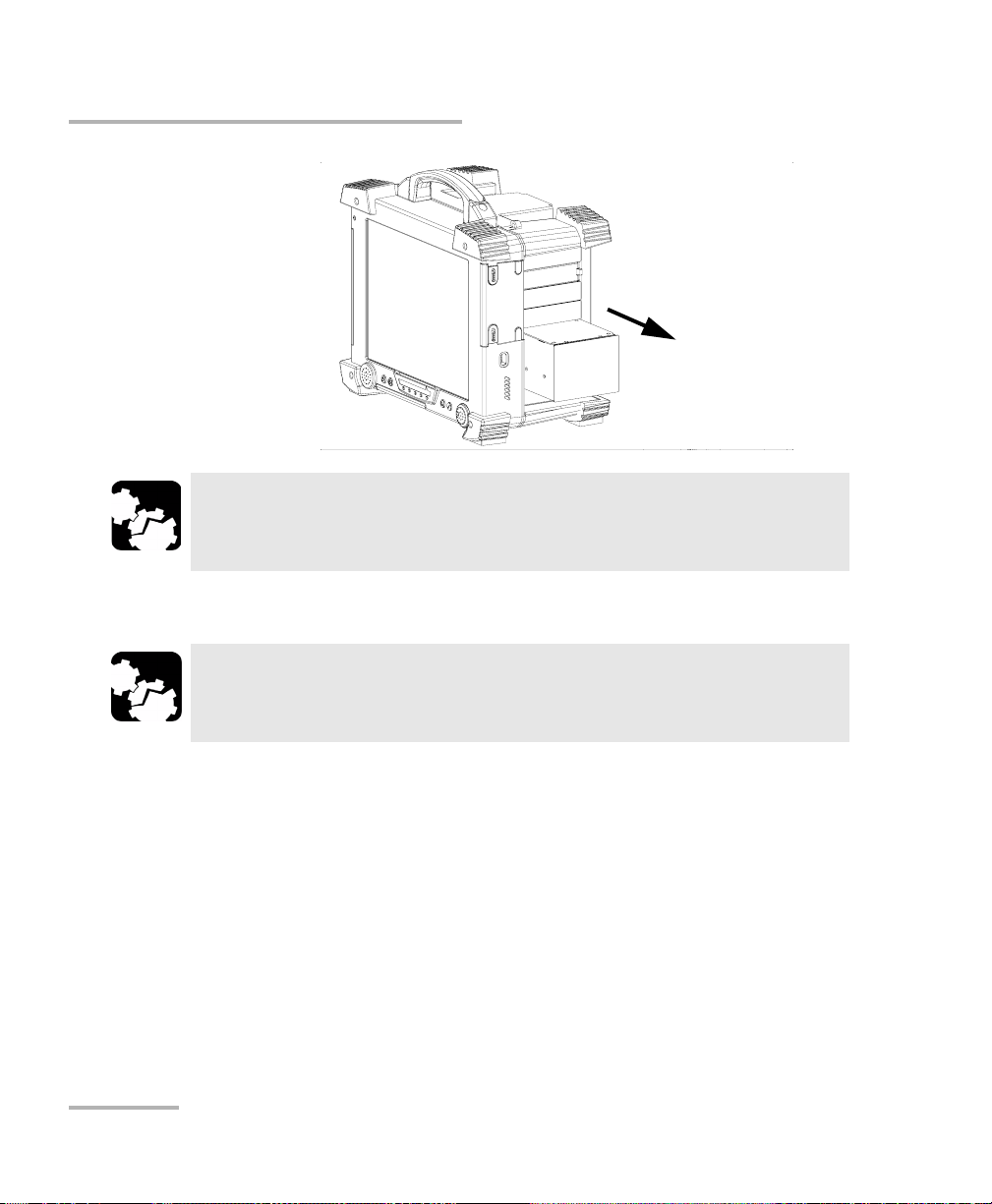
To remove a module from the FTB-400 Universal Test System:
1. Exit ToolBox and turn off your unit.
2. Position the FTB-400 so that the left panel is facing you.
3. Turn the retaining screw counterclockwise until it stops. The module
will be slowly released from the slot.
4. Place the FTB-400 so that the right panel is facing you.
5. Hold the module by its sides or by the handle (NOT by the connector)
and pull it out.
FTB-400 left panel
(2-slot or 4-slot receptacles)
Turn retaining screw knob(s)
counterclockwise
FTB-400 left panel
(7-slot or 8-slot receptacles)
Getting Started with Your MultiTest Module
12 FTB-3930
Inserting and Removing Test Modules
6. Cover empty slots with the supplied protective covers.
CAUTION
Pulling out a module by a connector could seriously damage both
the module and connector. Always pull out a module by its casing.
CAUTION
Failure to reinstall protective covers over empty slots will result in
ventilation problems.
Getting Started with Your MultiTest Module
MultiTest Module 13
Starting the MultiTest Module Application
Starting the MultiTest Module Application
Your FTB-3930 MultiTest Module module may be fully configured and
controlled from its dedicated ToolBox application.
Note: For details about ToolBox, refer to the FTB-400 Universal Test System user
guide.
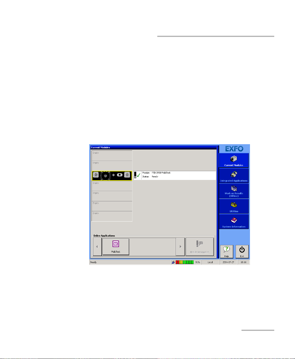
To start the MultiTest Module application:
1. From the Current Modules function tab, select the row corresponding
to the module you wish to use. It will turn white to indicate that it is
highlighted.
2. Press the corresponding button in the Online Applications box.

Getting Started with Your MultiTest Module
14 FTB-3930
Starting the MultiTest Module Application
The main window (shown below) contains all the commands required to
control the MultiTest Module:
Title Bar
The title bar is located at the top of the main window. It displays the
module name and its position in the FTB-400 Universal Test System. The
module position is identified as follows:
Note: On some 7-slot backplanes, slots are marked with a letter from A to G.
Status bar
Data display
Function
bar
Title bar
Slot number in which module is inserted
(0 identifies first slot)
Unit housing the module
(1 identifies FTB-400)
[1– 1]
Other manuals for FTB-3930
1
Table of contents
Other EXFO Test Equipment manuals

EXFO
EXFO Power Blazer User manual

EXFO
EXFO W2CM Series User manual

EXFO
EXFO FTB-3930 User manual

EXFO
EXFO RTU-2 User manual

EXFO
EXFO FTB-7000 Series User manual

EXFO
EXFO MAX-800 Series User manual

EXFO
EXFO ETS-1000 User manual

EXFO
EXFO Optical Explorer OX1 Operating manual

EXFO
EXFO BRT-320A User manual

EXFO
EXFO IQS-2150 User manual

EXFO
EXFO AXS-200/850 User manual

EXFO
EXFO IQS-600 Series User manual

EXFO
EXFO RTU-310 User manual

EXFO
EXFO RTU-2 User manual

EXFO
EXFO IQS-2100 User manual

EXFO
EXFO LTB Series User manual

EXFO
EXFO MaxTester Max-610 User manual

EXFO
EXFO IQS-2600B User manual

EXFO
EXFO LTS-3900 User manual

EXFO
EXFO FVA-600 User manual


