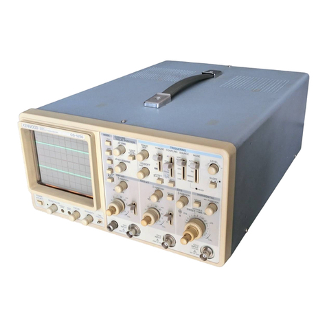
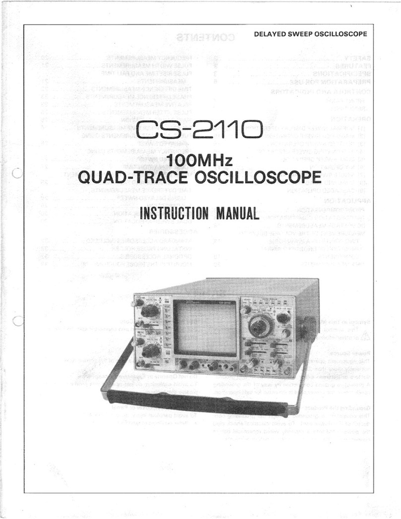
Kenwood CS-2075 User manual

DELAYEDSWEEPOSCILLOSCOPE
CS-2075
70MHz
QUAD-TRACEOSCILLOSCOPE
INSTRUCTIONMANUAL

CONTENTS
SAFETY2
FEATURES3
SPECIFICATIONS3
PREPARATIONFORUSE6
CONTROLSANDINDICATORS
FRONTPANEL7
REARPANEL13
OPERATION
[1]NORMALSWEEPDISPLAYOPERATION14
[2]MAGNIFIEDSWEEPOPERATION15
[3]DELAYEDSWEEPOPERATION15
[4]ALTERNATINGSWEEPOPERATION16
[5]X-YOPERATION16
[6]SINGLESWEEPOPERATION16
[7]DUALANDQUADTRACEOPERATION16
[8]CASCADEDOPERATION17
APPLICATION
PROBECOMPENSATION18
TRACEROTATIONCOMPENSATION18
DCVOLTAGEMEASUREMENTS18
MEASUREMENTOFTHEVOLTAGEBETWEEN
TWOPOINTSONA WAVEFORM19
ELIMINATIONOFUNDESIREDSIGNAL
COMPONENTS19
TIMEMEASUREMENTS• 20
FREQUENCYMEASUREMENTS20
PULSEWIDTHMEASUREMENTS21
PULSERISETIMEANDFALLTIME
MEASUREMENTS21
TIMEDIFFERENCEMEASUREMENTS22
PHASEDIFFERENCEMEASUREMENTS23
RELATIVEMEASUREMENTS23
PULSEJITTERMEASUREMENTS25
SWEEPMULTIPLICATION25
DELAYEDSWEEPTIMEMEASUREMENTS....26
PULSEWIDTHMEASUREMENTSUSING
DELAYEDSWEEP26
FREQUENCYMEASUREMENTSUSING
DELAYEDSWEEP27
PULSEREPETITIONTIME27
USINGDELAYEDSWEEPFORMEASUREMENT
OFRISETIMESANDFALLTIMES28
TIMEDIFFERENCEMEASUREMENTS
USINGDELAYEDSWEEP28
X-YOPERATION29
QUADTRACEAPPLICATION30
ACCESSORIES
STANDARDACCESSORIESINCLUDED31
INSTALLINGPROBEHOLDER31
OPTIONALACCESSORIES31
MOUNTINGTHEPROBEPOUCH(MC-78)32
SAFETY
SymbolinThisManual
Thissymbolindicateswhereapplicablecautionaryor
otherinformationistobefound.
PowerSource
Thisequipmentoperatesfroma powersourcethatdoes
notapplymorethan250Vrmsbetweenthesupply
con-
ductorsorbetweeneithersupplyconductorandground.
Aprotectivegroundconnectionbywayofthegrounding
conductorinthepowercordisessentialforsafeoperation.
GroundingtheProduct
Thisequipmentisgroundedthroughthegrounding
con-
ductorofthepower
cord.
Toavoidelectricalshockplug
thepowercordintoa properlywiredreceptaclebefore
connectingtotheequipmentinputoroutputterminals.
UsetheProperPowerCord
Useonlythepowercordandconnectorspecifiedforyour
product.
UsetheProperFuse
Toavoidfirehazard,usea fuseofthecorrecttype.
DonotOperateinExplosiveAtmospheres
Toavoidexplosion,donotoperatethisproductinanex-
plosiveatmosphere.
DonotRemovecoverorPanel
Toavoidpersonalinjury,donotremovethecoveror
pan-
el.
Referservicingtoqualifiedpersonnel.
2

FEATURES
•Smallandcompactwithhigh1 mV/divsensitivityand
70MHzbandwidth(1mV/divwhenX5GAINfunction
isusedand500/zV/divforcascadedoperation,channel
1tochannel2).
•Bright150mmrectangularCRTwithaninternalgrati-
culeanda 12kVacceleratingpotential.
•Verticalaxisiscapableofsingle,dualaswellasquad-
tracedisplay.
•The20MHzbandwidthlimiterincorporatedeliminates
high-frequencynoisesandstabilizessignalwaveforms
displayed.
•Singlesweep,X10magnification,delayedsweepand
alternatingsweepcapabilityareprovided.
•Fast50ns/divsweepspeed(5ns/divwithX10magnifi-
cation).
•Accuraciesofverticalaxisandhorizontalsweepingare
ashighas± 2%at10~ 35°C.
•TheVIDEOsynchronizationcircuitpermitstoobserve
videosignaleasily.
•Thedualintensitycontrolcircuitpermitstovaryinten-
sitiesseparatelyforA andB sweeps.
•A switchingtypepowersupplyprovidesstableopera-
tionwithvaryingpowersources(90V~ 264V).
•A convenientchannel1 samplingoutputisprovided.
•CPUcontrolledswitchingwithLEDlightedpushbutton
switchesprovideseasy.TheLEDoftheswitches
indi-
cateasfollowswhensupplyingpowerstarts.
VerticalMODE: CH1
HORIZDISPLAY: A
TRIGMODE: AUTO
SPECIFICATIONS
CRT
Model:
150LTM31
Type:
Rectangular,withinternal
graticule
Acceleratingpotential:12kV
Displayarea:8 divx 10div(1div= 1 cm)
VERTICALAXIS(Channel1 andChannel2 identical
specifications)
Sensitivity5mV/divto5V/div(X1mode)
1mV/divto
1
V/div(X5mode)
500/zV/div(Cascadedopera-
tion,
CH1toCH2)
Accuracy:±2%(10~ 35°C)
±5%(0~ 50°C)
±8%(Cascadedoperation,
CH1toCH2)
Attenuator:5mV/divto5V/divin
1
-2-5
sequence,all10rangeswith
fineadjustmentbetweensteps.
Inputresistance:1 MQ ±
1
%
Inputcapacitance:Approx22pF
Frequencyresponse
DC:
DCto70MHz(-3dB)
DCto90MHz(-6dB)
DCto40MHz(-3dB)
(Cascadedoperation,CH1to
CH2)
DCto50MHz(-3dB)(X5
mode)
AC:
5 Hzto70MHz(-3dB)
5Hzto90MHz(-6dB)
7Hzto40MHz(-3dB),
(Cascadedoperation,
CH1toCH2)
5Hzto50MHz(-3dB)(X5
mode)
Risetime:5ns(X1mode)
7ns(X5mode)
Signaldelaytime:Approx10nsasdisplayed
onCRTscreen
Crosstalk:-40dBminimum
Operatingmodes:
CH1CH1,singletrace
CH2CH2,singletrace
DUALCH1andCH2,dualtrace
ADDCH1+ CH2(added)display
QUADCH1~ CH4,quadtrace
ALTDualorquadtracealternating
CHOPDualorquadtracechopped
CHOPfrequency:Approx250kHz
ChannelpolarityNormalorinverted,CH2 only
inverted
AMaximuminputvoltage:
800Vp-por400V(dc+ ac
peak)
3

SPECIFICATIONS
Maximumundistorted
amplitude:8 divisions,minimum(DCto
70MHz)
Bandwidthlimiting:Verticalsystembandwidth
withthe20MHzBWpushbut-
tonswitchpushedisapproxi-
mately20MHz
VERTICALAXIS(Channel3 andChannel4 common
specifications)
Sensitivity0.1V/div,± 2%
Inputresistance:1 MQ ±
1
%
Inputcapacitance:Approx.22pF
Inputcouplingmode:DConly
Frequencyresponse:DCto70MHz(-3dB)
DCto90MHz(-6dB)
Risetime:5ns
Signaldelaytime:SameasCHIandCH2
Maximumallowablevoltage
DCcomponent:±0.5Vorless(ac+ dc)
ACcomponent:1 Vp-porless
AMaximuminputvoltage:400V(dc+ acpeak)
HORIZONTALAXIS(Channel2 input)
Modes:X-Ymodeisswitchselectable
(HORIZDISPLAY)
X-Ymode:CH1:Y-axis
CH2:
X-axis
Sensitivity:SameasCH2
Accuracy:SameasCH2
Inputresistance:SameasCH2
Inputcapacitance:SameasCH2
Frequencyresponse:
DC:
DCto5 MHz(-3dB)
DCto7 MHz(-6dB)
AC:
5 Hzto5 MHz(-3dB)
5Hzto7 MHz(-6dB)
X-Yphasedifference:Lessthan3°at100kHz
SWEEP
Modes(switchablewiththeHORIZ
DISPLAYswitch):
AA sweep
ALTB sweepwaveformisdis-
playedasanintensifiedpor-
tionoftheA sweepandB
sweepalternating
A-INT-BB sweepwaveformisdis-
playedasanintensifiedpor-
tionoftheA sweep.
BDLY'DDelayedB sweep
X-YX-Ydisplaymode
Asweeptime:50ns/divto
0.5s/div
in22
ranges,in
1
-2-5sequence,
verniercontrolprovides
fullyadjustablesweeptime
betweensteps.
Bsweeptime:50ns/divto50ms/divin19
ranges,in1-2-5sequence.
Accuracy±2%(10~ 35°C)
±6%(0~ 50°C)
Sweepmagnification:X10±5%(10~ 35°C)
±7%(0~ 50°C)
Linearity:50ns/divto
0.5s/div
±3%
(±5%withX10magnifica-
tion)
HOLDOFF:ContinuouslyadjustableforA
sweepfromNORMtoX5
Traceseparation:B positionableupto4
divisionsseparatedfromA
sweep,continuouslyadjusta-
ble.
Delaymethod:Continuousdelay.Triggerde-
lay
Delaytime:0.2to10timesthesweep
timefrom200nsto0.5s,
con-
tinuouslyadjustable.
Timedifferencemeasurementaccuracy:
±2%
(10~
35°C)
±4%(0~
50°C)
Delayjitter:
1
/20000ofthefullscale
sweeptime.
TRIGGERING
ATRIG
Atriggermodes:AUTO,NORM,SINGLE,
Triggersource:V MODE,CH1,CH2,EXTCH3
Couplingmodes:AC,
LFREJ,HFREJ,
DC,VIDEO
VIDEO-LINEsyncautomatical-
lyselectedatsweeptimesof
50/is/divto50ns/div.
VIDEO-FRAMEsyncautomati-
callyselectedatsweeptimes
of
0.5s/div
to0.1ms/div.
Triggerlevel:± 90°adjustable
Polarity:+/-
4

SPECIFICATIONS
BTRIG
Triggersource:CH1,CH2,EXTCH4
STARTSAFTERDELAY
Couplingmodes:AConly
Triggerlevel:± 90°adjustable
Polarity:+/-
TRIGGERSENSITIVITY(AANDB)
COUPLING FREQRANGE MINIMUMSYNCAMPLITUDE
COUPLING FREQRANGE INT EXT
DC DC~ 20MHz
DC~ 70MHz 0.5div
1.5div 50mV
210mV
AC SameasforDCbutwithincreasedminimumlevel
forbelow20Hz.
AC
HFREJ Increasedminimumlevelbelow20Hzandabove
30kHz.
AC
LFREJ
Increasedminimumlevelbelow30kHz.
VIDEO FRAME/LINE 0.5div 50mV
AUTO:
Sameasabovespecificationsforabove50Hz.
Jitter:1nsmaximum
(At70MHz)5ns/div(X10MAGon)
CALIBRATINGVOLTAGE
1kHz± 3%Positivesquarewave
1Vp-p±1%(10~ 35°C)
±2%(0~ BOX)
INTENSITYMODULATION
Inputsignal:TTLlevel,intensitydecreasing
withmorepositivelevels
Inputimpedance:Approx.10kQ
Usablefrequencyrange:DCto10MHz
AMaximuminputvoltage:50V(dc+ acpeak)
VERTICALAXISOUTPUT(SampledCH1output)
Outputvoltage:50mVp-p/div(into50D load)
Outputimpedance:Approx.50X2
Frequencyresponse:DCto70MHz(-3dB)
(into50X2load)
TRACEROTATIONElectrical,adjustable
POWERSUPPLY
Linevoltage:90~ 264V
Linefrequency:45~ 400Hz
Powerconsumption:Approx.55W(at100V,50Hz)
DIMENSIONS
Width:
284mm(328mm)
Height:138mm(150mm)
Depth:
400mm(471mm)
() dimensionsincludepro-
trusionsfrombasiccaseout-
linedimensions.
WEIGHT7.4kg
ACCESSORIES
PC-29Probes2
Instructionmanual1
ACpowercord1
Probeholder1
OPTION
Accessorybag(MC-78)
Panelcover(MD-85)
ENVIRONMENT
Operatingtemperatureand
Humidityforguaranteed
specifications:10~ 35°C,85%maximumRH
Fulloperatingrange:0 ~ 50°C,90%maximumRH
Storagetemperatureand
humidityrange:-20~ +70°C
80%
maximum
Altitude:
Operating:5000m
Non-operating:12000m
•Circuitandratingsaresubjecttochangewithoutnoticedueto
developmentsintechnology.
5

PREPARATIONFORUSE
SAFETY
Beforeconnectingtheinstrumenttoa powersource,care-
fullyreadthefollowinginformation,theverifythatthe
properpowercordisusedandtheproperlinefuseisin-
stalledforpowersource.Ifthepowersourceisnotap-
pliedtoyourproduct,contactyourdealer.Ifthepower
cordisnotappliedforspecifiedvoltage,thereisalwaysa
certainamountofdangerfromelectricshock.
Linevoltage
Thisinstrumentoperatesusingac-powerinputvoltages
that90Vto264Vatfrequenciesfrom45Hzto400Hz.
Powercord
Thegroundwireofthe3-wireacpowerplugplacesthe
chassisandhousingoftheoscilloscopeatearthground.
Donotattempttodefeatthegroundwireconnectionor
floattheoscilloscope;todosomayposea greatsafetyha-
zard.
Theappropriatepowercordissuppliedbyanoption
thatisspecifiedwhentheinstrumentisordered.
TheoptionalpowercordareshowninFig40.
Linefuse
Thefuseholderislocatedontherearpanelandcontains
thelinefuse.Verifythattheproperfuseisinstalledbyre-
placingthelinefuse.
5.Alwaysusetheprobegroundclipsforbestresults.Do
notuseanexternalgroundwireinlieuoftheprobe
groundclips,asundesiredsignalsmaybeintroduced.
6.Operationadjacenttoequipmentwhichproduces
strongacmagneticfieldsshouldbeavoidedwherepos-
sible.
Thisincludessuchdevicesaslargepowersup-
plies,
transformers,electricmotors,etc.,thatareoften
foundinanindustrialenvironment.Strongmagnetic
shieldscanexceedthepracticalCRTmagneticshield-
inglimitsandresultinterferenceanddistortion.
7.Probecompensationadjustmentmatchestheprobe
totheinputofthescope.Forbestresults,compen-
sationofprobeshouldbeadjustedinitially,thenthe
sameprobealwaysusedwiththeinputofscope.
Probecompensationshouldbereadjustedwhenever
aprobefroma differentscopeisused.
8.TheLEDsoftheswitchesindicateasfollows
whensupplyingpowerstarts.
VerticalMODE:CH1,
HORIZDISPLAY:A
TRIGMODE:AUTO
EQUIPMENTPROTECTION
1.
Neverallowa smallspotofhighbrilliancetoremain
stationaryonthescreenformorethana fewseconds.
Thescreenmaybecomepermanentlyburned.A spot
willoccuronlywhenthescopeissetupforX-Yopera-
tionandnosignalisapplied.Eitherreducetheintensity
sothespotisbarelyvisible,switchbacktonormal
sweepoperationwhennosignalisapplied,orsetup
thescopeforspotblanking.
2.
Nevercovertheventilatingholesonthetopoftheos-
cilloscope, asthiswillincreasetheoperatingtempera-
tureinsidethecase.
3.Neverapplymorethanthemaximumratingtotheoscil-
loscopeinputjacks.
CH1,
CH2INPUTjacks:800Vp-por400V(dc+ ac
peak)
CH3,
CH4INPUTjacks:400V(dc+ acpeak)
ZaxisINPUTjack:50V(dc+ acpeak)
Neverapplyexternalvoltagetotheoscilloscopeoutput
terminals.
4.
Alwaysconnecta cablefromtheearthground(GND)
jackoftheoscilloscopetothechassisoftheequipment
undertest.Withoutthiscaution,theentirecurrentfor
theequipmentundertestmaybedrawnthroughthe
probeclipleadsundercertaincircumstances.Such
conditionscouldalsoposea safetyhazard,whichthe
groundcablewillprevent.
6

CONTROLS
ANDINDICATORS
Fig.
1
FRONT
PANEL
VERTICAL
AXIS
CONTROL
©VOLTS/DIVControl
Verticalattenuatorforchannel1;providesstepad-
justmentofverticalsensitivity.WhentheVARIABLE
controlisturnedtotheCALposition,thevertical
sen-
sitivityiscalibratedin10stepsfrom5V/divto5 mV/
div.
ForX-Yoperationthiscontrolprovidesstepadjust-
mentofverticalsensitivity.
©VARIABLE,PULLX5GAINControls
VARIABLE;
Rotationprovidesfinecontrolofchannel1 vertical
sensitivity.Inthefullyclockwise(CAL)position,the
verticalattenuatoriscalibrated.ForX-Yoperation,
thiscontrolservesastheY axisattenuationfinead-
justment
PULLX5GAIN;
Whenpulledout,theVOLTS/DIVsettingismultiplied
byfiveandforX-YoperationtheY-axissensitivityis
multipliedaccordingly.InX5GAINmode,thevertical
gainisincreasedandthetracebecomesthickness.
©| CH1POSITION,| CH3Controls
$CH1POSITION;
Rotationadjustsverticalpositionofchannel1 trace.
InX-Yoperation,rotationadjustsverticalpositionof
display.
7
|CH3;
Rotationadjustsverticalpositionofchannel3 trace
onthescreen.
©AC-GND-DCswitch
Three-positionleverswitchwhichoperatesas
fol-
lows:
AC:
Blocksdccomponentofchannel1 input
sig-
nal.
GND:
Openssignalpathandgroundsinputto
verti-
calamplifier.Thisprovidesa zero-signalbase
line,
thepositionofwhichcanbeusedasa re-
ferencewhenperformingdcmeasurements.
DC:
Directinputofacanddccomponentofchan-
nel1 inputsignal.
©INPUTJack
Verticalinputforchannel1 traceinnormalsweep
operation.
VerticalinputforX-Yoperation.
©VOLTS/DIVControl
Verticalattenuatorforchannel2;providesstepad-
justmentofverticalsensitivity,VARIABLEcontrolis
turnedtotheCALposition,theverticalsensitivity
cali-
bratedin10stepsfrom5V/divto5mV/div.ForX-Y
operationthecontrolprovidesstepadjustmentofhor-
izontalsensitivity.

CONTROLSANDINDICATORS
©VARIABLE,PULLX5GAINControls
VARIABLE;
Rotationprovidesfinecontrolofchannel2 vertical
sensitivity.Inthefullyclockwise(CAL)position,the
verticalattenuatoriscalibrated.ForX-Yoperation,
thiscontrolservesastheX axisattenuationfinead-
justment
PULLX5GAIN;
WhenpulledouttheVOLTS/DIVsettingismultiplied
byfiveandforX-YoperationtheX-axissensitivityis
multipliedaccordingly.InX5GAINmode,thevertical
gainisincreasedandthetracebecomesthickness.
(DCH2* POSITIONX-Y* CH4Controls
*CH2POSITION;
Rotationadjustsverticalpositionofchannel2 trace.
InX-Yoperationadjustshorizontalpositionofdisplay.
*CH4;
Rotationadjustsverticalpositionofchannel4 trace
onthescreen.
(DAC-GND-DCSwitch
Three-positionleverswitchwhichoperatesas
fol-
lows:
AC:
Blocksdccomponentofchannel2 input
signal.
GND:
Openssignalpathandgroundsinputto
verticalamplifier.Thisprovidesa zero-
signalbaseline,thepositionofwhichcan
beusedasa referencewhenperforming
dcmeasurements.
DC:
Directinputofacanddccomponentof
channel2 inputsignal.
®INPUTJack
Verticalinputforchannel2 traceinnormalsweep
operation.
HorizontalinputinX-Yoperation.
®MODESwitchAssembly
Usedtoselectthebasicoperatingmodesofthe
osci-
lloscope.LED'sindicatewhatmodehasbeenselect-
ed.
CH1:
Onlytheinputsignaltochannel1 isdis-
playedasa singletrace.
CH2:
Onlytheinputsignaltochannel2 isdis-
playedasa singletrace.
DUAL:Whenengagedthisbutton,ifeitherALT
orCHOPswitchispushedin,dualtrace
modepresentstracesofchannel1,
channel2 inputwaveforms.
ADD:
Channel1 andchannel2 inputsignals
areaddedandthesumisdisplayedasa
singletrace.WhentheCH2INVbutton
isengaged,thewaveformfromchannel
2issubtractedfromthechannel1 wave-
formandthedifferenceisdisplayedasa
singletrace.
QUAD:
Whenengagedthisbutton,ifeitherALT
orCHOPswitchispushedin,quadtrace
modepresentstracesofchannel1
throughchannel4 inputwaveforms
ALT:Alternatesweepisselectedregardlessof
sweeptimeasdualtrace(channel1 and
channel2)orquadtrace(channel1
throughchannel4)
CHOP:
Chopsweepisselectedregardlessof
sweeptimeatapproximately250kHzas
dualtrace(channel1 andchannel2)or
quadtrace(channel1 throughchannel
4).
CH2INV:IntheNORMposition(buttonreleased),
thechannel2 signalisnon-inverted.In
theINVposition(buttonengaged),the
channel2 signalisinverted.
20MHzBW:Limitstheverticalbandwidthtoapproxi-
mately20MHzwhenengagedthisbut-
ton.
NOTE:
Thevariousverticalmodesettingsarerelatedto
hori-
zontalmodeandtriggersource.Seethesectionson
HORIZDISPLAYandSOURCEfora descriptionofthis
relationship.
8

CONTROLSANDINDICATORS
POWERSUPPLY/CRTDISPLAYCONTROLS
©A INTENSITY,B INTENSITYControls
AllowsadjustmentofintensityfortheA sweepandB
sweeprespectively.
AINTENSITY;
AdjuststhetraceintensityfortheA sweepand
thedisplayintensityforX-Yoperation.
BINTENSITY;
AdjuststheintensityoftheB sweep.
®POWER,SCALEILLUMControls
Fullycounterclockwiserotation(offposition)turnsoff
oscilloscope.Clockwiserotationturnsonoscillos-
cope.
Furtherclockwiserotationofthecontrolin-
creasestheilluminationlevelofscale.
®LEDPilotLamp
Indicatesthatthepowersupplyhasbeenturnedon.
©ASTIGControl
Pulloutandrotatethisknob.Astigmatismadjust-
mentprovidesoptimumspotroundnesswhen
usedinconjunctionwithFOCUScontrolregard-
lessintensitycontrol.
®FOCUSControl
Usedtoadjustthetraceforoptimumfocus.
Auto-focuscircuitkeepswaveforminfocuswith
changesinintensity.
®TRACEROTATIONControl
Electricallyrotatestracetohorizontalposition.
Strongmagneticfieldsmaycausethetracetobetilt-
ed.
Thedegreeoftiltmayvaryasthescopeismoved
fromonelocationtoanother.Inthesecases,adjust
thiscontrol.
©CAL,1Vp-p,w 1 kHzTerminal
Provides1kHz,
1
Voltpeak-to-peaksquarewave
sig-
nal.
Thisisusefulforprobecompensationadjust-
ment
®«LGNDTerminal/Bindingpost.
Groundterminal- useittoconnecttheinstrumentto
theearthground.
9
Fig.
2

Fig.
3
HORIZONTAL
AXIS
CONTROLS
©
HORIZ
DISPLAY
SWITCH
ASSEMBLY
Used
to
select
the
horizontaldisplaymode.LED's
indicatewhatmode
has
beenselected.
A:Only
A
sweep
is
operativewith
theB
sweep
dormant.
ALT:
A
sweepalternateswith
theB
sweep.
For
thismode
of
operation,
theB
sweep
ap-
pears
asan
intensifiedsection
ontheA
sweep.
A-INT-B:
Duration
oftheB
sweepappears
asanin-
tensifiedsection
ontheA
sweep.
BDLY'D:Onlydelayed
B
sweep
is
operative.
X-Y:Channel
1
becomes
the
Y-axis
and
channel
2becomes
the
X-axis
forX-Y
operation.
Thesettings
ofthe
verticalMODE
and
TRIG
MODEswitcheshave
no
effect.
©
A
SWEEPTIME/DIV,
B
SWEEPTIME/DIVCon-
trols
ASWEEPTIME/DIV;
Horizontalcoarse
A
sweeptimeselector.
Selectscalibratedsweeptimes
of50
ns/div
to0.5
s/div
in22
stepswhen
A
VARIABLEcontrol
® isset
to
CAL
position(fullyclockwise).
BSWEEPTIME/DIV;
Horizontalcoarse
B
sweeptimeselector.
Selectssweeptimes
of50
ns/div
to50
ms/div
in19
steps.
B
sweeptimeselector
is
constructed
to
make
itpossible
tosettheB
sweeptimeslowerthan
A
sweeptime.
No
fineadjustment
is
available
fortheB
sweeptime.
<§>
A
VARIABLEControl
Fine
A
sweeptimeadjustment.
Inthe
fullyclockwise
(CAL)position,
theA
sweeptime
is
calibrated.
@DELAYTIMEMULTControl
Adjusts
the
starttime
oftheB
sweep
to
somedelay
timeafter
the
start
oftheA
sweep.
Thedelaytime
maybesetto
valuesbetween
0.2and
10times
the
setting
oftheA
SWEEPTIME/DIV
con-
trol.
10

CONTROLSANDINDICATORS
©* TRACESEP,HOLDOFFControls
*TRACESEP;
AdjustsverticalseparationbetweenA sweepandB
sweep(controlhaseffectonlyintheALTofHORIZ
DISPLAY).
Counterclockwiserotationincreasesseparation;B
sweepmovesdownwithrespecttoA sweepupto4
divisions.Inthiscase,HOLDOFFcontrolhasno
effect.
HOLDOFF;
Rotationadjustsholdoff(triggerinhibitperiodbeyond
sweepduration).Counterclockwiserotationincreases
holdoffperiodfromNORMtomaxmorethanfive
timesbeforetheB ENDSA position.
IntheB ENDSA position(fullycounterclockwise),the
AsweepisresetattheendoftheB sweep.And
thereforeintensityofB sweepincreasestoprovide
theA sweep.B ENDSA modeisapplicabletothe
ALT,A-INT-BandB DLY'DmodesofHORIZDISPLAY.
<§>«•POSITION,FINE,PULLX10MAGControls
«•POSITION;
Rotationadjustshorizontalpositionoftrace.
FINE,
PULLX10MAG;
Rotationbecomesfineadjustmentofhorizontal
posi-
tionoftrace.Selectsx10sweepmagneification
(PULLx10MAG)whenpulledout.
TRIGGERSOURCECONTROLS
<§)SOURCESwitch
Four-positionleverswitch;selectstriggeringsource
fortheA sweep,withfollowingpositions;
V.MODE:ThetriggersourceforA sweepisdeter-
minedbyverticalMODEselection.
CH1:
Channel1 signalisusedasa trigger
source.
CH2:
Channel2 signalisusedasa trigger
source.
ADD:
Thealgebraicsumofchannel1 and
channel2 signalsisthetriggersource.
(IfCH2INVengaged,thedifferencebe-
comesthetriggersource.)
DUAL:ForALTmodethesignalsforCH1
QUAD:
throughCH4alternateasthetrigger
(ALT)source.FortheCHOPmodethechop-
(CHOP)pingsignalbecomesthetriggersource.
NOTE:
1.
WhentheverticalMODEswitchisse-
lectedtoCHOPposition,thedisplay
cannotbeobservedwiththeinputsince
thechoppingsignalbecomesthetrigger
source.
2.
Synchronizationisimpossiblewhenin-
putsignalsarenotappliedtoallchannels
withtheverticalMODEswitchsetto
DUALorQUADposition.
CH1:
A sweepistriggeredbychannel1 signalre-
gardlessofverticalMODEselection.
CH2:
A sweepistriggeredbychannel2 signalre-
gardlessofverticalMODEselection.
EXTCHS:A sweepistriggeredbychannel3 signal.
@COUPLINGSwitch
Five-positionleverswitch;selectscouplingforA
triggersignal.
AC:
Triggerisaccoupled.Blocksdccomponent
ofinputsignal;mostcommonlyused
posi-
tion.
LFREJ:
Triggeriscoupledthrougha high-passfilter
toeliminatelowfrequencycomponentsfor
stabletriggeringofhighfrequencysignals.
HFREJ:
Triggeriscoupledthrougha low-passfilter
toeliminatehighfrequencycomponents
fora stabletriggeringoflowfrequency
sig-
nals.
DC:
Triggerisdccoupledforsyncwhichincludes
theeffectsofdccomponents.Forchannel3
andchannel4,theverticalpositionadjust-
menthasnoeffectonthetriggerpoint.
VIDEO:Forsynchronizationofvideosignals.The
positionoftheA SWEEPTIME/DIVcontrol
determineswhetherFRAMEorLINEistobe
synchronized.Settingsbetween0.5sand
0.1msresultinFRAMEwhilethosebetween
50;isand50nsresultinLINEsync.
<§)LEVEL,SLOPEControls
LEVEL;RotationadjustspointonwaveformwhereA
sweepstarts.WhenCOUPLINGswitchisse-
lectedinVIDEO,thetriggerleveladjustment
hasnoeffect.
11

CONTROLSANDINDICATORS
SLOPE;
AdjuststheslopeoftheA triggersignal,
-fequalsmostpositivepointoftriggeringand
-equalsmostnegativepointoftriggering.
<§>TRIG'DLamp
GreenLEDlightsfordurationoftriggeredA sweep;
showswhentriggerLEVELcontrolisproperlysetto
obtaintriggering.
@CH3orA EXTTRIGJack
Inputterminalofchannel3 signalorA externaltrigger
signal.
Channel3 signalmaybeobservedsimultaneous-
lywithchannel1,2 and4 signalswhenthevertical
MODEswitchisselectedinQUAD.
WhentheSOURCEcontrolissettoEXTCH3,sweepis
triggeredbythisinputsignal.
@SOURCESwitch
Four-positionleverswitch;selectsthetriggeringsource
fortheB sweep,withfollowingpositions;
CH1:
B sweepistriggeredbychannel1 signal.
CH2:
B sweepistriggeredbychannel2 signal.
EXTCH4:B sweepistriggeredbychannel4 signal.
STARTSAFTERDELAY:
Bsweepstartsimmediatelyafterthedelaytime
selectedbytheDELAYTIMEMULTandA
SWEEPTIME/DIVcontrols,regardlessofthe
triggerLEVELsetting.Evenwhenthisswitchis
inpositionwiththeTRIGMODEswitchsetto
AUTO,
turningthetriggerLEVELclockwiseor
counterclockwisereleasethetriggerandsetthe
scopetoB STARTSAFTERDELAYoperation.
®LEVELSLOPE,Controls-
LEVEL:RotationadjustspointonwaveformwhereB
sweepstarts.
SLOPE:
AdjusttheslopeoftheB triggersignal,+equals
mostpositivepointoftriggeringand-equals
mostnegativepointoftriggering.ForB trigger
operationitmustbesetinitspushed-in
posi-
tion.
(§)TRIG'DLamp
GreenLEDlightsfordurationoftriggeredB sweep;
showswhentriggerLEVELcontrolisproperlysettoob-
taintriggering.
®CH4orB EXTTRIGJack
inputterminalforthechannel4 signaiorB external
triggersignal.Channel4 signalmay.beobserved
simultaneouslywithchannel1,2 and3 signalswhen
theverticalMODEisselectedinQUAD.
WhentheSOURCEswitchissettoEXTCH4,sweepis
triggeredbythisinputsignal.
(§>TRIGMODESwitch
Pushbuttonswitchassembly;selectstriggering
mode.
AUTO:
Triggeredsweepoperation.Whentrigger
signalispresent,automaticallygenerates
sweep(freerunsinabsenceoftriggersignal.)
NORM:
Normaltriggeredsweepoperation.Notrace
ispresentedwhena propertriggersignalis
notapplied.
SINGLE:Singlesweepoperation.Notethatinthis
mode,
simultaneousobservationofboththe
AandB sweepsisnotpossible.
NOTE:
Fordualorquadtrace,singlesweepopera-
tion,
verticalMODEmustnotbesettoALT.
UsetheCHOPmodeinstead.
RESET:WhenTRIGMODEswitchisselectedto
SIN-
GLEmode,pushingtheRESETbutton
ini-
tiatesa singlesweepwhichwillbeginwhen
thenextsynctriggeroccurs.
12

CONTROLS
ANDINDICATORS
Fig.
4
REAR
PANEL
<§)CH1OUTJACK
Channel1 verticaloutputsignalconnector.Ac
cou-
pledoutputconnector.Thisconnectorisusedto
measurethefrequencybyconnectingthefrequency
counter.
<§>Z.AXISINPUTJack
Externalintensitymodulationinput;TTLcompatible.
Positivevoltagedecreasesbrightness,negative
vol-
tageincreasesbrightness.
<§>POWERLINECONNECTOR
TheinputconnectorfortheACpower
cord.
<§)FUSEHOLDER
Containthelinefuse.Verifythattheproperfuseisin-
stalled(1.2A).
©Feet
Rearfeetsupportoscilloscopeinface-uppositionand
doubleascordwrapforstoringpower
cord.
Handle
Carryinghandlewithcomfortablemoldedfingergrip
alsodoublesastiltstand.Lockingdetenteach15°al-
lowsadjustmentofviewingangle.
13

OPERATION
Beforeturningthescopeon,setthefrontpanelcontrolsas
follows,referringtothesectiononfrontpanelinthisman-
ual.
[1]NORMALSWEEPDISPLAYOPERATION
1.
TurnthePOWERcontrol® clockwise- thepower
supplywillbeturnedonandthepilotlampwilllight
withtheotherLED'sforthepreviouslysetvertical
MODE®,HORIZDISPLAY® andTRIGMODE©
alsoiighting.
Setthesemodesasfollows:
VerticalMODE© : CH1
HORIZDISPLAY® : A
TRIGMODE© : AUTO
2.
ThetracewillappearinthecenteroftheCRTdisplay
andcanbeadjustedbythechannel1 ^ POSITION©
andPOSITION© controls.Next,adjusttheA IN-
TENSITY© and,ifnecessary,theFOCUS® forease
ofobservation.
3.VerticalMODE
WithverticalMODE© settoCH1,applyaninput
sig-
naltothechannel1 INPUT© jackandadjustVOLTS/
DIV© controlfora suitablesizedisplayofthewave-
form.
Operationwitha signalappliedtothechannel1
INPUT© jackandtheverticalMODEsettoCH2issi-
milartotheaboveprocedure.IntheADDmode,the
algebraicsumofchannel1 + channel2 isdisplayed.If
theCH2INVswitchhasbeenpressed,thealgebraic
dif-
ferenceofthetwowaveforms,channel1 - channel2 is
displayed.
Ifbothchannelsaresettothesame
VOLTS/DIV,thesumordifferencecanbereaddirectly
inVOLTS/DIVfromtheCRT.TheDUALmodeallows
simultaneousobservationofchannel1 andchannel2
waveforms.IntheDUALmode,eithertheCHOPorALT
modeappliesandmustbeselected.IntheALTmode,
onesweepdisplaysthechannel1 signalandthenext
sweepdisplaysthechannel2 signalinanalternating
sequence.IntheCHOPmode,thesweepischoppedat
anapproximate250kHzrateandswitchedbetween
channel1 andchannel2.NotethatintheCHOPmode
ofoperationwiththeSOURCE® switchsettoV
MODE,
thetriggersourcebecomesthechoppingsignal
itself,makingwaveformobservationimpossible.Use
ALTmodeinsteadinsuchcases,orselecttheSOURCE
switchtoCH1,CH2,orCHS.TheQUADmodeis
simi-
lartotheDUALmode,exceptitallowssimultaneous
viewingofchannel1 thruchannel4 inputsignals,in
eitherALTorCHOPmode.Thechannel3 andchannel
4POSITIONcontrols® and© becomeeffectivein
theQUADmodeforadjustingtheverticalpositionof
thechannel3 andchannel4 traces.Thechannel3 and
channel4 INPUTsignalsaredccoupledandhavea
sensitivityof0.1V/div.
14
Fig.
5

OPERATION
4.
Triggering
TheSOURCEswitch© selectsthesignaltobeusedas
thesynctrigger.WhentheV.MODEpositionisselect-
ed,
thetriggersourceisdependentuponthevertical
MODEselection.Inthismanner,eachwaveformbeing
observedbecomesitsowntriggersignal;e.g.,whenthe
verticalMODEischangedfromCH1toCH2,thesource
signalisalsochangedfromCH1toCH2.Thisalsoper-
mitssynchronizationofwaveforms(evenwithouta
timingrelationship)intheDUALandQUADmodes.
However,whenphaseortimingcomparisonisdesired
inDUALandQUADmodes,allwaveformsmustbe
trig-
geredbythesamesource,andtheV.MODEpositionis
unsuitable.Also,asexplainedpreviously,CHOPcannot
beusedinconjunctionwithverticalMODEinDUALor
QUADmodes.IftheSOURCEswitchissettotheCH1
(orCH2)position,thechannel1 (orchannel2)input
signalisthetriggersource,regardlessofthevertical
MODE.
CH1(orCH2)isoftenusedasthetrigger
sourcewhentimingcomparisonisdesired.Ifthe
SOURCEswitchissettotheCHSposition,thesignal
appliedtotheCHSorA EXTTRIGjackbecomesthe
triggersource.Thissignalmusthavea timingrelation-
shiptothedisplayedwaveformsfora synchronizeddis-
play.InQUADmode,thesignalappliedtotheCHSorA
EXTTRIGjackbecomesboththetriggersourceandthe
displayedchannel3 signal.
AftersettingtheSOURCEswitch,adjusttheLEVEL/
SLOPEcontrol@ tosetthetriggerpoint.Syncis
indi-
catedbythegreenTRIG'DLEDlighting.
Asnecessarytoobtaina stable,synchronizeddisplay,
adjusttheHOLDOFFcontrol© andCOUPLING©
switch.
5.AdjusttheA SWEEPTIME/DIVcontrol© foranap-
propriatedisplayofthesignalinput.Ifrequired,usethe
AVARIABLEcontrol© as
well.
6.ThiscompletestheoperatingprocedurefornormalA
sweepdisplay.
[2]MAGNIFIEDSWEEPOPERATION
Sincemerelyshorteningthesweeptimetomagnifya por-
tionofanobservedwaveformcanresultinthedesired
portiondisappearingoffthescreen,suchmagnifieddis-
playshouldbeperformedusingtheMAGNIFIEDSWEEP.
Procedure:
UsingthePOSITIONcontrol,adjustthedesiredportion
ofwaveformtothecenteroftheCRT.PullouttheFINE
PULLX10MAG© controltomagnifythedisplay10
times.
Forthistypeofdisplaythesweeptimeisthe
SWEEPTIME/DIVsettingdividedby10.
[3]DELAYEDSWEEPOPERATION
DelayedsweepoperationisachievedbyuseofboththeA
sweepandtheB sweep.
Procedure:
1.
FirstselecttheHORIZDISPLAYswitchtoA andadjust
thescopefora normalwaveformdisplay.
2.
SettheB SOURCEswitch® totheSTARTSAFTER
DELAY. SelecttheHORIZDISPLAYtotheA-INT-B
modeanda portionoftheB sweeprepresentingtheB
SWEEPTIME/DIVwillappearasanintensifiedportion
oftheA sweep.TheB sweepintensityisadjustedus-
ingtheB INTENSITYcontrol@.
3.Shifttheintensifiedportionofwaveform(sectiontobe
magnified)alongtheA sweepbyuseoftheDELAY
TIMEMULT<§>.
4.
SelecttheHORIZDISPLAYswitchtoB DLY'Dtodis-
playtheA-INT-Bintensifiedportionasa magnifiedB
DLY'Dsweep.
DelayTime(magnifiedportion)= DELAYTIMEMULT
settingx A SWEEPTIME/DIVsetting.
5.ForSTARTSAFTERDELAYoperation,apparentjitter
increasesasmagnificationincreases.Toobtaina jitter
freedisplay,settheB SOURCEswitch® ina position
similartothatofcorrespondingforA SOURCE.Inthis
modethesignalselectedbytheB SOURCEswitchbe-
comestheB triggersource,makinguseoftheB trigger
LEVEL<§>controltosetthetriggerpoint.B SOURCE,
andLEVEL/SLOPEcontrolsaresetina mannersimilar
tothatofthecorrespondingcontrolsforA sweep.
Fig.
6
15
Intensifiedzonetobemagnified
A-INT-B
BDLY'D

OPERATION
NotethatfortypeofoperationboththeDELAYTIME
MULTandtriggerLEVELaffectthestartoftheB sweep
sothatthedelaytimeisusedasa referencepoint.
[4]ALTERNATINGSWEEPOPERATION
AsweepandB sweepareusableinanalternatingmode
makingitpossibletoobserveboththenormalandmagni-
fiedwaveformsimultaneously.
Procedure:
1.
SelecttheHORIZDISPLAYswitchtoA andadjustthe
scopefora normalwaveformdisplay.
2.
SettheB SOURCEswitchtoSTARTSAFTERDELAY
andselecttheHORIZDISPLAYtoALT.AdjustTRACE
SEP© foreasyobservationofboththeA andB
traces.
Theuppertraceisthenon-magnifiedportionofthe
waveformwiththemagnifiedportionsuper-imposedas
anintensifiedsection.Thelowerwaveformisthein-
tensifiedportiondisplayedmagnified.
BINTENSITYcanbeusedtoadjusttheintensityofthe
super-imposedwaveform.
3.TheDELAYTIMEMULTcontrolcanbeusedtocontin-
uouslyslidethemagnifiedportionofthewaveform
acrosstheA sweepperiodtoallowmagnificationof
preciselythedesiredportionofwaveform.
4.
Apparentdisplayjitterincreaseswithincreasedmagni-
ficationasisthecasewithdelayedsweepdiscussed
above.BycancellingtheSTARTSAFTERDELAYmode,
BtriggerLEVELcontrolcanbeusedtosetthetrigger
point.
Fig.
7
[5]X-YOPERATION
Phasedifferencemeasurementsmaybemadebyuseof
theX-Ydisplaymode.
Procedure:
SelecttheHORIZDISPLAYswitchtotheX-Ymode.In
thismodethechannel1 inputbecomestheY-axisinput
andthechannel2 inputtheX-axisinputforX-Ydisplay.
ForX-YoperationtheX andY positionsareadjustedusing
thechannel2 * POSITION,X-Yandchannel1 *
POSI-
TIONcontrolsrespectively.
XandY sensitivitiesaresetbyusingthechannel2 and
channel1 VARIABLE,VOLTS/DIVcontrolsrespectively.
BypullingoutthetwoabovementionedVARIABLE
con-
trols,
thesensitivitiesofboththeX andY axisaremagni-
fiedby5 times.A INTENSITYcontrolisusedtoadjustthe
intensityofthedisplayduringX-Yoperation.
[6]SINGLESWEEPOPERATION
Thismodeofdisplayisusefulforlookingatnon-
synchronousoronetimeevents.
Procedure:
1.
SelecttheTRIGMODEtoeitherAUTOorNORM.
Applya signalofapproximatelythesameamplitude
andfrequencyasthesignalthatistobeobservedas
thetriggersignaiandsetthetriggerLEVEL.
2.
SelectTRIGMODEtoSINGLEandpresstheRESET
button- observethattheredLEDlightstoindicatethe
resetcondition.ThisLEDgoesoutwhentheA sweep
periodiscompleted.
3.Aftertheaboveset-upiscompletedthescopeisready
tooperateintheSINGLEsweepmodeofoperation
afterresettingthescopeusingtheRESETbutton.Input
ofthetriggersignalresultsinoneandonlyonesweep.
NOTE:
•
WiththeHORIZDISPLAYselecttoALT,thesimultan-
eousobservationoftheA sweepandB sweepwave-
formsatSINGLEsweepmodeisnotpossible.Alsofor
DUALorQUADoperationsimultaneousobservationis
notpossibleusingALTmode.Setthescopetothe
CHOPmodeinthiscase.
[7]DUALANDQUADTRACEOPERATION
BysettingtheverticalMODEtoDUALorQUAD,Dualand
Quadtraceoperationscanbeachieved.Additionallyse-
lectingtheHORIZDISPLAYtoALTproducesuptoan8
trace.
Operationofthevariouscontrolsisforthistypeofdisplay
modesimilartotheoperationdescribedaboveforAlter-
natingsweepoperation.
16
Intensifiedzonetobemagnified
(Asweep)
(Bsweep)

OPERATION
[8]CASCADEDOPERATION
Thismodeofoperationisusedwhensensitivitygreater
than1mV/divisrequired.
Procedure:
1.
ConnecttheCH1 OUTjacktothechannel2 inputjack
usinga BNCcablethroughthe50Q termination.
2.
Forcascadeoperationdonotpullthechannel1 and
channel2 X5GAINswitchestowardyou.
3.SelectverticalMODEtoCH2.
4.
Setthechannel1 andchannel2 VOLTS/DIVto5mV
andinputa signalfora sensitivityof500^V/divon
channel1.
17

APPLICATION
PROBECOMPENSATION
Ifaccuratemeasurementsaretobemade,theeffectofthe
probebeingusedmustbeproperlyadjustedoutputofthe
measurementsystemusingtheinternalcalibrationsignal
orsomeothersquarewavesource.
1.
Connecttheprobetothechanneltobeusedandset
thevariouscontrolsfora normalA sweepdisplay.
2.
AdjusttheSWEEPTIME/DIVcontrolfordisplayof
severalcyclesofthesignalfromthecalibrationoutput,
CAL,
terminal.
3.Adjusttheprobecompensationcontrolfora proper
waveformdisplay.
4.
Theotherchannelsarecompensatedforinthesame
way.
Correct
compensation
Over
compensation
Insufficient
compensation
TRACEROTATIONCOMPENSATION
Rotationfroma horizontaltracepositioncanbethecause
ofmeasurementerrors.
Adjustthescopecontrolsfora normaldisplay.Setthe
AC-GND-DCswitchtoGNDandTRIGMOtfEswitchto
AUTO.
Adjustthe* POSITIONcontrolsuchthatthetraceisover
thecenterhorizontalgraduationline.
Ifthetraceappearstoberotatedfromhorizontal,alignit
withthecentergraduationlineusingtheTRACEROTA-
TIONcontrollocatedonthefrontpanel.
DCVOLTAGEMEASUREMENTS
Thisproceduredescribesthemeasurementprocedurefor
dcwaveforms.
Procedure:
1.
Connectthesignaltobemeasuredtothevertical
INPUTjackandselecttheverticalMODEtothechannel
tobeused.
SettheVOLTS/DIVandSWEEPTIME/DIVcontrolsto
obtaina normaldisplayofthewaveformtobemea-
sured.
SettheVARIABLEcontroltotheCAL
2.
SelecttheTRIGMODEswitchtoAUTOandAC-GND-
DCswitchtoGND,whichestablishesa traceatthe'
zerovoltreference.Usingthe* POSITIONcontrol,ad-
justthetracepositiontothedesiredreferencelevelpo-
sition,
makingsurenottodisturbthissettingonce
made.
3.SettheAC-GND-DCswitchtotheDCpositiontoob-
servethewaveform,includingitsdccomponent.Ifan
appropriatereferencelevelpositionwasselectedin
step3 oraninappropriateorVOLTS/DIVsettingwas
made,
thewaveformmaynotbevisibleontheCRTat
thispoint(deflectedcompletelyoffthescreen).Thisis
especiallytruewhenthedccomponentislargewithre-
specttothewaveformamplitude.Ifso,resetVOLTS/
DIVand/orthe* POSITIONcontrol.
4.
UsethePOSITIONcontroltobringtheportionof
thewaveformtobemeasuredtothecenterverticalgra-
duationlineofthegraticulescale.
5.Measuretheverticaldistancefromthereferencelevel
tothepointtobemeasured,(thereferencelevelcanbe
recheckedbymomentarilyreturningtheAC-GND-DC
switchagaintoGND).
MultiplythedistancemeasuredabovebytheVOLTS/
DIVsettingandistheprobeattenuationratioas
well.
If
"x 5 GAIN"hasbeensetmultiplythevalueby1/5as
weli.
Voltagesaboveandbelowthereferencelevelare
posi-
tiveandnegativevaluesrespectively.
Usingtheformula:
Dclevel= Verticaldistanceindivisionsx (VOLTS/DIVset-
ting)x (probeattenuationratio)x "x 5 GAIN"value(1/5)
Measuringpointadjustedtothe
centerverticalscaleby<«•POSITION
18
Fig.
8
Groundpotentialadjustedby
Y
position(referenceline)
Fig.
9
[EXAMPLE]
FortheexampleshowninFig.9,thepointbeingmea-
suredis3.8divisionsfromthereferencelevel(groundpo-
tential).
IftheVOLTS/DIVwassetto0.2Vanda 10: 1 probewas
used.
Substitutingthegivenvalues:
Dclevel= 3.8(div)x 0.2(V)x 10= 7.6V
Vertical
distance

APPLICATION
MEASUREMENTOFTHEVOLTAGE
BETWEENTWOPOINTSONA WAVEFORM
Thisproceduremaybeusedtomeasurepeak-topeak
vol-
tages,
orformeasuringthevoltagedifferencebetweenany
twopointsona waveform.
Procedure:
1.
ApplythesignaltobemeasuredtotheINPUTjack,se-
lecttheverticalMODEtothechanneltobeusedand
settheAC-GND-DCswitchtoAC,adjustingVOLTS/
DIVandSWEEPTIME/DIVcontrolsfora normaldis-
play.SettheVARIABLEcontroltoCAL
2.
Usingthe^ POSITIONcontroladjustthewaveformpo-
sitionsuchthatoneofthetwopointsfallsona major
graduationline.
3.UsingthePOSITIONcontrol,adjustthesecond
pointtocoincidewiththecenterverticalgraduation
line.
4.
Measuretheverticaldistancebetweenthetwopoints
andmultiplythenumberofdivisionsbythesettingof
theVOLTS/DIVcontrol.
Ifa probeisused,furthermultiplythisbytheprobeat-
tenuationratio,ifanyandif'x5 GAIN"isused,multiply
thevalueby1/5as
well.
Usingtheformula:
VoltsPeak-to-Peak
=Verticaldistance(div)x (VOLTS/DIVsetting)
x(probeattenuationratio)x "x5 GAIN"value"1(1/5)
Adjusttothecenter
verticalscalewithPOSITION.
-
Pointstobemeasured
ELIMINATIONOFUNDESIREDSIGNAL
COMPONENTS
TheADDfeaturecanbeconvenientlyusedtocancelout
theeffectofanundesiredsignalcomponentwhichissup-
erimposedonthesignalyouwishtoobserve.
Procedure:
1.
Applythesignalcontaininganundesiredcomponentto
thechannel1 INPUTjackandtheundesiredsignalitself
alonetothechannel2 INPUTjack.
2.
SelecttheverticalMODEswitchtoDUAL(CHOP)and
SOURCEswitchtoCH2.Verifythatchannel2 repre-
sentstheunwantedsignalinreversepolarity.Ifneces-
sary,reversepolaritybysettingCH2toINV.
3.SelecttheverticalMODEswitchtoADD,SOURCE
switchtoV MODEandCH2VOLTS/DIVandVARIABLE
controlssothattheundesiredsignalcomponentis
can-
celledasmuchaspossible.Theremainingsignal
shouldbethesignalyouwishtoobservealoneandfree
oftheunwantedsignal.
Adjusttothehorizontalscale
with$ POSITION
Fig.
10
[EXAMPLE]
FortheexampleshowninFig10,thetwopointsaresepa-
ratedby4.4divisionsvertically.LettheVOLTS/DIVset-
tingbe0.2V/divandtheprobeattenuationbe10: 1.
Substitutingthegivenvalue:
Voltagebetweentwopoints= 4.4(div)x 0.2(V)x 10
=8.8V
Signalcontainingundesiredcomponent
(Brokenlines:undesiredcomponentenvelope)
Undesiredcomponentsignal
19
Vertical
distance
betweentwopoints.

APPLICATION
•
Adjusttothevertical
scalewith<>POSITION
TIMEMEASUREMENTS
Thisistheprocedureformakingtimemeasurementsbet-
weentwopointsona waveform.Thecombinationofthe
SWEEPTIME/DIVandthehorizontaldistanceindivisions
betweenthetwopointsisusedinthecalculation.
Procedure:
1.
ApplythesignaltobemeasuredtotheINPUTjackand
se;
cttheverticalMODEswitchtothechanneltobe
used.
AdjustVOLTS/DIVandSWEEPTIME/DIV
con-
trolsfora normaldisplay.
BesurethattheVARIABLEcontrolissettoCAL.
2.
Usingthe^ POSITIONcontrolsetoneofthepointsto
beusedasa referencetocoincidewiththehorizontal
centerline.
Usetheo POSITIONcontroltosetthispointatthein-
tersectionofanyverticalgraduationline.
3.Measurethehorizontaldistancebetweenthetwo
points.
MultiplythisbythesettingoftheA SWEEPTIME/DIV
controltoobtainthetimebetweenthetwopoints.If
horizontal"x10MAG"isused,multiplythisfurtherby
1/10.
Usingtheformula:
Time= Horizontaldistance(div)x (SWEEPTIME/DIVset-
ting)x "x10MAG"value1(1/10)
[EXAMPLE]
FortheexampleshowninFig.12,thehorizontaldistance
betweenthetwopointsis5.4divisions.
IftheSWEEPTIME/DIVis0.2ms/divwecalculate.
Substitutingthegivenvalue:
Time= 5.4(div)x 0.2(ms)= 1.08ms
Horizontaldistance Adjusttohorizontalcenter
linewith* POSITION
Fig.
12
FREQUENCYMEASUREMENTS
Frequencymeasurementsaremadebymeasuringtheper-
iodofonecycleofwaveformandtakingthereciprocalof
thistimevalueasthefrequency.
Procedure:
1.
Settheoscilloscopeuptodisplayonecycleofwave-
form(oneperiod).
2.
Thefrequencyisthereciprocaloftheperiodmeasured.
Usingtheformula:
Freq- perjoc|
20
Signalwithoutundesiredcomponent
Fig.
11
1cycle= 40//s(5yus/div.x 8 div.)
Fig.
13
[EXAMPLE]
FortheexampleshowninFig.13,a periodof40/is is
observedandmeasured.
Substitutingthegivenvalue:
Freq=
1
/[40x 10"6]= 2.5x 104= 25kHz
Table of contents
Other Kenwood Test Equipment manuals

Kenwood
Kenwood CS-5165 User manual

Kenwood
Kenwood CS-5230 User manual

Kenwood
Kenwood CAX-AD100 User manual

Kenwood
Kenwood CS-5170 User manual

Kenwood
Kenwood CO-1303D User manual

Kenwood
Kenwood CS-2110 User manual

Kenwood
Kenwood CS-4125 User manual

Kenwood
Kenwood CS-1065 User manual

Kenwood
Kenwood CS-6020 User manual

Kenwood
Kenwood CS-1720 User manual

Kenwood
Kenwood CS-5140 User manual

Kenwood
Kenwood CO-1506 User manual

Kenwood
Kenwood CS-5130 User manual

Kenwood
Kenwood CS-5130 User manual

Kenwood
Kenwood CS-5135 User manual

Kenwood
Kenwood CS-3025 User manual

Kenwood
Kenwood CS-5200 Series User manual

Kenwood
Kenwood AG-203 User manual

Kenwood
Kenwood CS-8010 User manual

Kenwood
Kenwood TH-77A User manual