Emcotec RC Electronic DPSI RV Mini Series User manual

Bedienungsanleitung

DPSI RV Mini Family Operating Instructions Version 1.0
Page 2 of 54
Contents
1. Preface .............................................................................................4
2. History..............................................................................................5
3. DPSI RV Mini at a glance................................................................6
4. Overall layout ................................................................................11
5. Characteristics .............................................................................. 12
5.1. Dual Current Supply ..............................................................13
5.2. Electronically Switches..........................................................13
5.3. Detached Voltage Regulators................................................14
5.4. Servo Current Distribution .....................................................15
5.5. APP (Advanced Push Pull Servo Pulse Amplification)..........15
5.6. HFIB (High Frequency Interference Blocking).......................16
5.7. Built-in V-Cable......................................................................16
5.8. Servo-Matching ("Magic" option only)....................................16
6. Error Detection and Indication..................................................... 17
6.1. IVM (Intelligent Voltage Monitoring).......................................17
7. Safety Features of DPSI RV Systems.......................................... 18
8. Contents of Delivery .....................................................................20
9. Mounting Hints and Programming .............................................. 21
9.1. Mounting the DPSI RV Mini...................................................21
9.2. Hole-Spacing for Mounting....................................................22
9.3. Mounting the Receiver...........................................................22
9.4. Connecting the Switch Actuator.............................................23
9.5. Connecting the Receiver .......................................................27
9.6. Selecting Batteries.................................................................28
9.7. Soldering Battery Sockets .....................................................31
9.8. Charging the Batteries...........................................................32
9.9. Setting the Voltages...............................................................33
9.10. Programming the Batteries..................................................35
9.11. Connecting Servos ..............................................................38

DPSI RV Mini Family Operating Instructions Version 1.0
Page 3 of 54
10. Servo-Matching ........................................................................... 39
10.1. Programming .......................................................................40
10.2. Changing Servo Direction....................................................41
10.3. Setting Servo Center ...........................................................41
10.4. Setting End-Limits................................................................42
10.5. Deletion of all Programming ................................................43
10.6 Supplemental Hints for MAGIC-Version ...............................43
10.7. Changing the Model.............................................................44
10.8. Sequence of Programming..................................................44
10.9. Limitation of Range Settings................................................44
10.10. Technical Data of Servo-Matching.....................................45
11. Connecting Optional Products .................................................. 46
12. Operating ..................................................................................... 46
13. Error Indication ...........................................................................47
14. Safety Directions......................................................................... 50
15. Technical Data of DPSI RV Mini-Systems.................................52
16. Warranty.......................................................................................53

DPSI RV Mini Family Operating Instructions Version 1.0
Page 4 of 54
1. Preface
With a DPSI RV Mini dual current supply from EMCOTEC you
purchased a high grade, modern and secure product for your remotely
controlled model. We appreciate your trust and assure you that you
made the right choice!
Long lasting experience for years in development and manufacturing of
electronically systems as well as the knowledge of the world’s best
model airplane pilots has influenced the development. All products are
developed by experienced engineers and manufactured at EMCOTEC
GmbH in Germany on our own production line. Extensive optically and
electronically end tests for every system, which leaves our house,
assure that you, our customer acquire an absolute reliable product,
which considerably increases the reliability of your valuable RC-Model.
Of course, the products not only have been tested extensively in the
laboratory, but also went through intensive flight-testing. Extensive
series of tests with especially in house developed data loggers have
been accomplished to measure the real current consumption in model
airplanes. Like done in the automobile industry FMEA (Failure Mode
and Effect Analysis) reduces the possibility of damage and malfunction
on operating errors to a minimum.
Hint:
We kindly ask you to read these operating instructions carefully and to
observe the installation hints. Thus, errors can be avoided in advance.
We are all ears for your wishes and questions. Challenge us!
Bobingen, October 2008
The Staff of EMCOTEC GmbH

DPSI RV Mini Family Operating Instructions Version 1.0
Page 5 of 54
2. History
For all times, EMCOTEC was and is the leader in "safe current
supplies" around RC-Models. Novelties and developments were
initiated by EMCOTEC:
•First dual current supply with servo current distribution and
electronically switches (DPSI 2001)
•First and only "genuine" fail-proof switch actuator for current supplies;
no mechanical influences or microcontroller errors can lead to
malfunctions (DPSI pin switch actuator)
•First LiPo capable dual current supply with regulated output voltage
(DPSI RV Mini, DPSI RV)
•First provider of LiPo-Batteries for supplying receivers (LongGo und
LongGo „S“)
•First and only provider who's products output error information
acoustically (e.g. low voltage)
•First dual current supply with integrated receiver-switches worldwide
(DPSI TWIN)
•First remote control system which transmits in two different
frequencies (HF TWIN)
•First LiPo capable dual current supply with LC-Display for indicating
all relevant data (DPSI BIC)
•First electronically fuse with current monitor which shuts off defective
servos causing an overload (DPSI OCP)
•First electronically switches which are actuated contact free using a
magnet instead of any mechanically switching elements (e.g. push
buttons or switches)
•Smallest and most light weight LiPo capable dual current supply of its
class (DPSI Micro – DPSI RV)
•First receiver switch with 16 channels (DPSI TWIN Mini)
•First dual current supply with integrated receiver switch, 16 channels
and LC-Display (DPSI TWIN Maxi)
•First dual current supply with separate supply voltage for receiver,
servos and pulse amplifiers and integrated servo-matching (DPSI RV
Mini 5/6 Magic)
Innovation and Quality – Made in Germany by EMCOTEC!
DPSI RV Mini Family Operating Instructions Version 1.0
Page 6 of 54
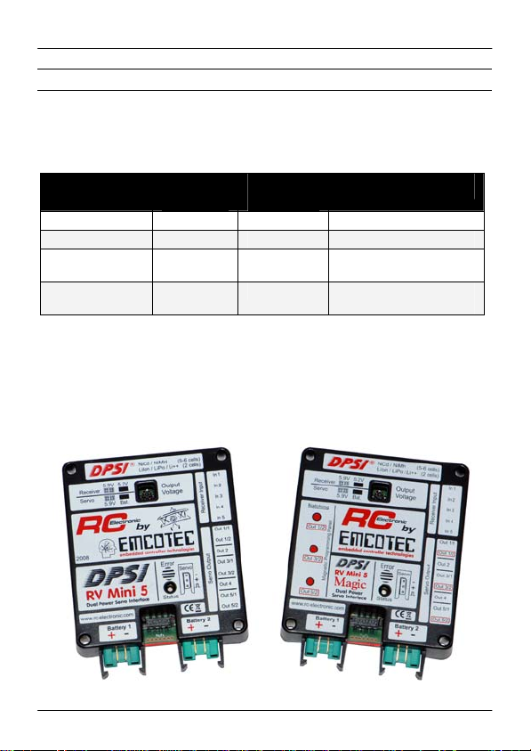
3. DPSI RV Mini at a glance
The DPSI RV Mini – family consists of four different dual current
supply systems with servo current distribution for models of medium
size which fit all applications:
DPSI Version Receiver-
channels Servo-
connections Specifics
DPSI RV Mini 5 5 8 3 built in V-cable
DPSI RV Mini 6 6 7 1 built in V-cable
DPSI RV Mini 5
Magic 5 8 3 built in V-cable with
servo-matching
DPSI RV Mini 6
Magic 6 7 1 built in V-cable with
servo-matching
The DPSI RV Mini 5 corresponds to pilots of the 2m to 2.7m air
acrobatic class who need up to 10 servos and where up to 2 servos
actuate one rudder. Therefore, only heavy loaded rudders are supplied
by the DPSI (aileron, elevator and yaw rudder). Servos for additional
functions (e.g. engine, retractable landing gear, etc.) are connected
directly to the receiver.

DPSI RV Mini Family Operating Instructions Version 1.0
Page 7 of 54
The DPSI RV Mini 6 is mainly used by jet- and glider-pilots (as well as
engine driven planes and helicopters) were more channels are
necessary but only one powerful servo actuates one rudder. Here too,
additional (less powered) servos can be directly supplied by the
receiver.
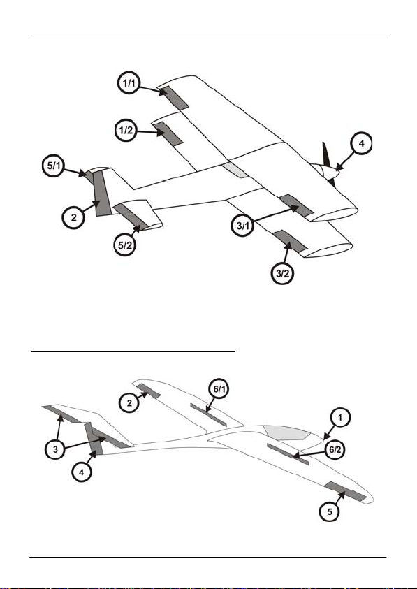
Examples for the DPSI RV Mini 5 (Magic)
An acrobatic airplane with 2 servos per aileron and 2 servos for the yaw rudder. The throttle
servo is directly connected to the receiver.
DPSI RV Mini Family Operating Instructions Version 1.0
Page 8 of 54
A biplane with 4 aileron servos, split elevator- and one yaw-rudder servo. The throttle servo
may be directly connected to the receiver as an option.
Examples for the DPS RV Mini 6 (Magic)
A glider with spoilers and tow release.

DPSI RV Mini Family Operating Instructions Version 1.0
Page 9 of 54
A glider with flaps and spoilers. The yaw rudder (and if so one tow release) are directly
connected to the receiver.
An acrobatic airplane with one servo per rudder, the yaw rudder is actuated by 2 servos.

DPSI RV Mini Family Operating Instructions Version 1.0
Page 10 of 54
A jet with flaps and spoilers. The turbine-ECU is directly connected to the receiver,
as well as landing gear doors or other electronically systems.
A helicopter with 4-point-control of swash plate (2 roll- und 2 pitch-servos). 1 = throttle. The
gyro (tail rotor) is supplied directly by the receiver (5.2V) or via channel 6/1 of the DPSI (5.9V).
DPSI RV Mini Family Operating Instructions Version 1.0
Page 11 of 54
In these examples, the outputs of the DPSI RV Mini are assigned to
the corresponding rudders. Outputs at the DPSI are labeled "Out 1/1",
"Out2", and so on.
Additional servos and auxiliaries can be directly connected to the
receiver.
Hint:
Assignment of the receiver channels to the DPSI is totally arbitrary and therefore
not stringent. Mapping according to the manufacturer (e.g. channel 1 = throttle,
etc.) is not necessary. Receiver channel 3 can be connected to DPSI input 1 just
as well. Any combination is allowed and possible.
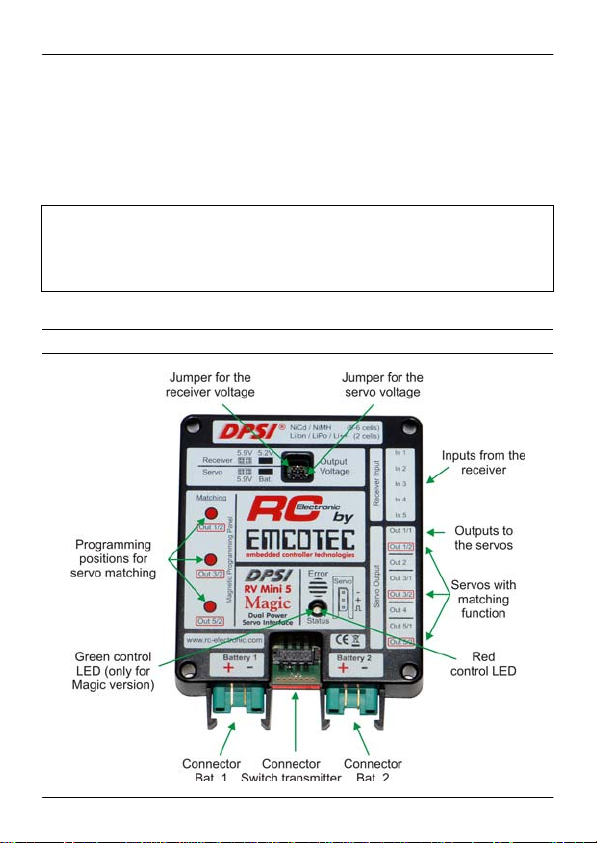
4. Overall layout

DPSI RV Mini Family Operating Instructions Version 1.0
Page 12 of 54
5. Characteristics
With the DPSI RV Mini - systems a new dimension is reached as far
as safety and comfort about current supplies for RC receiver
equipment is concerned:
Dual current supply (battery switch)
Separate electronically high power switches for both batteries
Up to 50A peak current load
Switching without microcontroller and therefore failsafe (CSHC=
Controller-less Self Holding Circuitry)
Possibility to connect an external LED voltage indicators onto switch
actuator
Due to voltage regulators usage of all battery types available
Selectable output voltage for receiver
Selectable output voltage for servos
Usage of 7.4V servos unlimited
Compliant to all RC receiver-equipment's manufacturers
specifications
Continuously constant servo power due to constant voltage supply
Servo current distribution for heavy loaded servos in system
Optimal recognition and conditioning of servo signals from 2.7V
receivers
Short-circuit proof servo pulse amplifier in current-saving APP-
Technology (Advanced Push Pull) for each individual servo
HFIB (High Frequency Interference Blocking) suppression of induced
HF interference caused by long servo cables (for each individual
servo)
Built-In "V-cable“ for connecting two servos per channel
Servo-matching for built-in "V-cable“ (in Magic versions)
Failsafe function of programmable servos (in Magic versions)
Optically and acoustically warnings on malfunctions, e.g. battery low
voltage or total battery loss
IVM (Intelligent Voltage Monitoring) – intelligent voltage monitoring
with acoustically and optically state indication for six different battery
types (programmable)
Protection of receiver against the so-called "Dynamo Effect“
(feedback of servo counter electromotive force)
Cable free system, i.e. all lines are pluggable and therefore
replaceable at any time
Special grounding concept for flawless operation and highest safety

DPSI RV Mini Family Operating Instructions Version 1.0
Page 13 of 54
High grade plastic housing with integrated latches for battery
connectors
Large area heat sink for heat dissipation
Each system 100% tested and provided with individual serial number
Delivery inclusive all accessories
Developed and manufactured by market leader (Made in Germany)
5.1. Dual Current Supply
First of all the DPSI RV Mini is a dual current supply with regulated
output voltage which allows for usage of all commercially available
batteries as a receiver power supply (NiCd, NiMH, LiIon, LiPo, LiFePo,
etc.).
It's a dual current supply because two batteries can be connected to
the system. If one battery fails, secure operation is guaranteed by the
second battery. Normally, both batteries are discharged equally at the
same time. Additionally, current drawn from each battery is cut in half
due to the two batteries connected in "parallel" which allows for
batteries with lower current load capabilities.
5.2. Electronically Switches
The batteries are switched using fail-proof electronically switches. The
external switch actuator only generates the On/Off signal. Power is
switched by highly loadable semiconductors. Thanks to the
electronically switches there is no power loss, contacting problems or
transition resistance. All DPSI RV Mini systems are built with separate
electronically switches, i.e. all electronics are dual. The switches are
fail-proof and are controlled by a self holding circuitry (not by means of
a microcontroller!).
An operating DPSI RV Mini stays turned on even if the On/Off switch
actuator is removed or broken or should the microcontroller
malfunction.

DPSI RV Mini Family Operating Instructions Version 1.0
Page 14 of 54
5.3. Detached Voltage Regulators
Until now, the receiver set was supplied directly by the connected
battery (or corresponding battery switch). The output voltage of
batteries depends heavily on the actual discharging state. Because 5-
cell NiCd or NiMH batteries are utilized more often for optimal servo
power, a fully charged battery reaches voltages up to 7.5V after turning
the charger off. Although this peak voltage usually drops quickly it can
shorten the life cycle of servos in adverse cases because servos
usually are approved only for 6V by the manufacturer. Due to
increased usage of light weight Lithium Polymer batteries voltage
regulation is mandatory because these batteries carry a nominal
voltage of 7.4V.
The electronics in the DPSI RV Mini make sure that the voltage is
reduced to a permissible value, independent of the higher input voltage
of the battery. Jumper (small pluggable bridges) allow for selection of
the desired output voltage. This way, the power requirements can be
adapted to the pilot needs and technical data of the servos.
As a specialty, two separate voltage regulators are built into the DPSI
RV Mini each having its own selectable output voltage. Servos directly
connected to the DPSI are supplied by their own voltage regulator. Its
output voltage is either 5.9V or battery voltage. This means: the servos
are supplied either with a regulated 5.9V (regular permissible voltage)
or directly with the (unregulated) battery voltage. Later is about 7.4V for
2-cell LiPo batteries. Some servos can be supplied with this higher
voltage already.
A receiver connected to the DPSI RV Mini is supplied by its own
voltage regulator. This is very advantageous and gains safety
significantly.
The output voltage of the receiver can be set between 5.2V and 5.9V.
Besides direct connections of high power servos the concept of the
DPSI RV Mini allows for connection of additional low power servos to
the receiver (e.g. a throttle servo), where 5.2V normally suffice.

DPSI RV Mini Family Operating Instructions Version 1.0
Page 15 of 54
Even fast tail rotor servos or gyro systems which only "allow for" small
voltages can be supplied by the receiver with 5.2V. Additionally, the
receiver supply is protected against voltage peaks. This means: all
disturbing pulses induced into the supply voltage are limited to safe
values.
5.4. Servo Current Distribution
Furthermore, a DPSI RV Mini provides current distribution for high
power servos, in order not to connect these to the sensitive receiver.
All servos directly connected to the DPSI RV Mini are supplied with full
power and each individual servo gets its maximum possible current.
This can be recognized by a significantly better servo actuating force.
5.5. APP (Advanced Push Pull Servo Pulse Amplification)
In order to provide each servo optimally conditioned control signals
from the receiver, these signals are electronically amplified. This is
especially important if receivers operate on low voltage (e.g. 2.7V);
their pulse amplitude is too low for some servos.
Each individual servo output of the DPSI RV Mini has its own pulse
amplifier and specific HF suppression. The amplifiers recognize even
very weak servo signals from the receiver and elevate the level up to
an exactly defined value. They are short-circuiting proof and are
supplied with their own voltage regulator for safety reasons (i.e. not
with the regular servo voltage). Therefore, the signals always carry a
defined and constant level over the total operating range.
An additional advantage is the current-saving APP-Technology. The
amplifiers consist of special output stages which actively control the
low- as well as the high-phase of the servo signal. In connection with
highly effective filters which practically eliminate induced disturbances
caused by long servo cables completely, best pulse quality and highest
possible safety is guarantied.

DPSI RV Mini Family Operating Instructions Version 1.0
Page 16 of 54
5.6. HFIB (High Frequency Interference Blocking)
In order to even increase safety, a highly effective filter is looped in into
each servo's signal path. Disturbances, "caught" by long servo cables
are almost completely eliminated directly at the servo connector and
therefore do not reach the receiver. Ferrite cores, as often utilized, can
be omitted, which saves weight and cost. The filters in the DPSI RV
Mini are tremendously more effective than cheap ferrite cores; their
effectiveness is controversial anyway.
5.7. Built-in V-Cable
Depending on the system (Mini 5 or Mini 6) V-cables are built in to the
DPSI. This means, two servos can be connected to one receiver
output. This is especially handy, if two servos actuate one rudder (e.g.
the aileron of a larger acrobatic plane). The DPSI RV Mini 5 has three,
the Mini 6 one built-in V-cable (e.g. for the yaw rudder and nose gear).
5.8. Servo-Matching ("Magic" option only)
DPSI RV Mini with "MAGIC" option allow for setting the servos which
are connected to V-cables arbitrarily, i.e. direction, center- and end-
limit positions.
This means: one receiver channel serves actually two servos; their
direction, center position and end positions can be aligned. A split
elevator rudder can be controlled by one servo on each side with one
single receiver channel. Therefore one receiver channel and one mixer
in the transmitter get freed up.
The same holds true for controlling the yaw rudder with coupled nose
gear. Here too, "matching" helps to adapt both servos and saves one
channel.
There is no external programming device (e.g. a PC) necessary for
programming or adapting the servos. A delivered magnet initiates
programming.
DPSI RV Mini Family Operating Instructions Version 1.0
Page 17 of 54
Each matching system has its own microcontroller (there are three in
the DPSI RV Mini 5 Magic, one in the DPSI RV Mini 6 Magic).
Resolution (precision) is more than 3000 steps and the delay of the
servo signals is only 1500 micro-seconds!
6. Error Detection and Indication
6.1. IVM (Intelligent Voltage Monitoring)
An internal microcontroller monitors all voltages using an intelligent
algorithm and indicates different errors (overload, low voltage, voltage
errors, battery malfunctions) acoustically by means of a built-in piezo-
buzzer. Furthermore, errors are visualized by blink codes by a LED in
the switch actuator.
Additionally, the DPSI RV Mini allows for connection of external LED-
Displays (battery monitors) directly at the switch actuator.
In order for the DPSI RV Mini to detect low voltages correctly the
battery type must be programmed once. Simple programming allows
for selection of 6 different battery types.

DPSI RV Mini Family Operating Instructions Version 1.0
Page 18 of 54
Hint:
At delivery, low voltage recognition of the DPSI RV Mini systems is programmed
for 2-cell LiPo batteries. If other battery types are to be used, the corresponding
battery type must be programmed in first place (see chapter 9.10.)!
Output voltages for receiver and servos are both set to 5.9 volts at delivery.
7. Safety Features of DPSI RV Systems
Because of the results of FMEA and an elaborate design DPSI RV
Mini is especially safe:
Short-circuits at contacts of the male multi point connector where the
switch actuators cable is connected to, do not damage the DPSI RV
Mini. Therefore even not a defective (squeezed) switch actuator cable.
Shorts on servo pulse lines, no matter whether to ground or positive,
do not any damage, too. All other servos of that channel, where there
is a short-circuit pending, remain fully functional. Even reverse polarity
of a servo does not harm to the DPSI RV Mini.
Mistakenly shorted servo cables usually burn up or melt without
damaging the DPSI RV Mini. The heat sink naturally gets very hot at
events like this!
Both batteries are totally decoupled and also the electronically
switches (inclusive peripheral electronics) are doubled. There are no
dual diodes (two diodes in one housing) built in. Therefore, no
malfunctioning part can cause total fail of the system. This circuitry has
been proven outstandingly several thousand times.
A DPSI RV Mini must not be disconnected from its batteries during
long breaks (e.g. in winter time) because the self discharge of the
batteries is much higher than the quiescent current consumption which
practically is not measurable.

DPSI RV Mini Family Operating Instructions Version 1.0
Page 19 of 54
In order to allow for optical power-on control, an ultra bright LED has
been built into the switch actuator of the DPSI RV Mini. It signals
power-on and low voltage or other errors of the battery / batteries by
blinking even over large distances.
All commercially available remote control systems (JR, Futaba,
Multiplex, Spektrum) with all available modulations (PCM, SPCM,
PCM1024, PPM, IPD), 2.4GHz as well, were tested in connection with
DPSI RV Mini systems. Therefore all systems can be utilized with no
problems.
Receivers which are supplied with 2.7 volts internally (e.g. Futaba
6014), can be used without hesitation, because the servo pulses in the
DPSI RV Mini are already recognized at 1.6 volts reliably. Servo
amplifiers in the DPSI RV Mini are supplied by their own voltage which
is totally independent from the regular servo and receiver voltage.
Therefore, voltage peaks and voltage drops do not have any influence
to the pulse quality. Due to its sophisticated safety features in
connection with elaborate testing, operating errors and outside
influences usually do not lead to damage of the DPSI RV Mini.
DPSI RV Mini Family Operating Instructions Version 1.0
Page 20 of 54
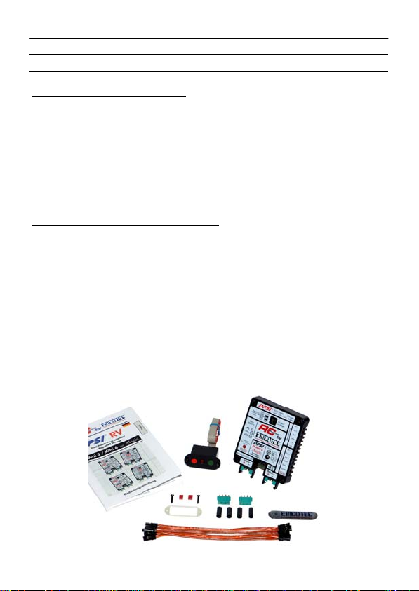
8. Contents of Delivery
Delivery of DPSI RV Mini 5 (6):
"DPSI RV Mini 5 (6)“ Base Device
On/Off switch actuator with pin and mounting material
5 (6) pieces receiver connection cables (with servo
connectors on both ends => patch cable)
2 pieces MPX high-current sockets for the batteries
4 pieces of shrink tubing for MPX high-current sockets
2 pieces of voltage selection jumpers
Operating instructions, EMCOTEC 3D sticker
Delivery of DPSI RV Mini 5 (6) Magic:
"DPSI RV Mini 5 (6) Magic" Base Device
On/Off switch actuator with pin and mounting material
5 (6) pieces receiver connection cables (with servo
connectors on both ends => patch cable)
Switching-magnet for programming of the matching-functions
2 pieces MPX high-current sockets for the batteries
4 pieces of shrink hoses for MPX high-current sockets
2 pieces of voltage selection jumpers
Operating instructions, EMCOTEC 3D sticker
Each individual DPSI RV Mini system carries its own serial number
and is tested several times prior to delivery!
This manual suits for next models
4
Table of contents
Other Emcotec Recording Equipment manuals


