Emcotec RC Electronic DPSI RV User manual

Operating Instructions

DPSI RV Family Operating Instructions Version 2.0
Page 2 of 48

DPSI RV Family Operating Instructions Version 2.0
Page 3 of 48
Contents
1. Foreword..........................................................................................4
2. Features ...........................................................................................6
3. The DPSI RV-Family in Headwords.............................................11
3.1. HFIB (High Frequency Interference Blocking).......................13
3.2. APP (Advanced Push Pull Servo Pulse Amplification)..........13
3.3. IVM (Intelligent Voltage Monitoring).......................................14
3.4. Safety Features of the DPSI RV Systems.............................14
4. Packing Contents..........................................................................16
5. Installation Instructions and Programming................................17
5.1 Installing the DPSI RV............................................................17
5.2. Hole spacing for Fastening....................................................19
5.3. Connecting the Switch transmitter.........................................20
5.4. Connecting the Receiver .......................................................23
5.5. Selecting the Batteries...........................................................25
5.6. Soldering the Battery Connectors..........................................28
5.7. Charging the Batteries...........................................................29
5.8. Setting the Voltage ................................................................30
5.9. Programming of the Batteries................................................32
5.10. Connecting the Servos ........................................................35
5.11. Connecting Accessories......................................................37
5.12. EMCOTEC Filter Capacitor .................................................38
6. Operation ....................................................................................... 39
7. Error Indication .............................................................................40
8. Safety Instructions........................................................................42
9. Technical Data of the DPSI RV-Systems..................................... 44
10. Warranty.......................................................................................46

DPSI RV Family Operating Instructions Version 2.0
Page 4 of 48
1. Foreword
With the EMCOTEC DPSI RV (Dual Power Servo Interface –
Regulated Voltage) you purchased a high grade, modern and secure
product. We appreciate your trust and assure you that you made the
right choice!
Long lasting experience for years in development and manufacturing of
electronically systems as well as the knowledge of the world’s best
model airplane pilots has influenced the development of the DPSI
systems. All products are manufactured at EMCOTEC GmbH in
Germany on our own production line. Extensive optically and
electronically end tests for every system, which leaves our house,
assure that you, our customer acquire an absolute reliable product,
which considerably increases the reliability of your valuable RC-Model.
Of course, the products of the DPSI family not only have been tested
extensively in the laboratory, but also went through intensive flight-
testing. Extensive series of tests with especially in house developed
data loggers have been accomplished to measure the real current
consumption in model airplanes. Like done in the automotive industry
an FMEA (Failure Mode and Effective Analysis) reduces the possibility
of damage and malfunction on operating errors to a minimum.
We kindly ask you to read these operating instructions carefully and to
observe the installation hints. Thus, errors can be avoided in advance.
We are all ears for your wishes and questions. Challenge us!
Bobingen, June 2006
The Staff of EMCOTEC GmbH

DPSI RV Family Operating Instructions Version 2.0
Page 5 of 48
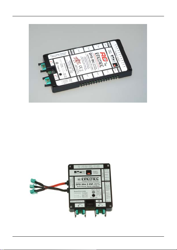
Connection sam
p
le of the DPSI RV Mini 5

DPSI RV Family Operating Instructions Version 2.0
Page 6 of 48
2. Features
A DPSI RV is used as a redundant power supply and current distributor
for receivers and servos in RC-Models. The redundancy is
accomplished by using two connected batteries. If one battery fails, the
second battery guaranties safe operation. In the normal case, both
batteries are discharged simultaneously. Furthermore, current is cut in
half in each single battery by the two “parallel” connected batteries,
which allows for batteries with lower ampacity.
All servos directly connected to a DPSI RV are supplied with full power
and each servo obtains maximum current without burden the
damageable receiver.
Due to switching the supply voltage electronically (the switch
transmitter does not switch on the current but only supplies a switch-on
signal), there is no power loss, weak contacts or transition resistance.
For all DPSI RV systems, the electronically switches are built
separately, i.e. the electronically parts are doubled. The switches are
failsafe and are driven by self-holding circuitry, rather by a micro-
controller. Thus, an operating DPSI RV stays powered on, even if the
on/off switch transmitter is removed or broken or if the microcontroller
is malfunctioning.
Using DPSI RV systems, RC receiver sets reach new dimensions. In
particular, a stabilized output voltage, which supplies the receiver as
well as all servos, accounts for. A DPSI RV therefore offers:
Battery switching function
Complete voltage regulation for all RC components
Electronically, failsafe switches
Current distribution with HF filtering
Battery voltage monitoring with acoustically warnings

DPSI RV Family Operating Instructions Version 2.0
Page 7 of 48
Voltage Regulation:
Until now, the receiver set was supplied directly by the connected
battery (or a corresponding battery switch). The output voltage
depends heavily on the current discharge state. Because virtually
always 5-cell NiCad or NiMH batteries are being used in large model
airplanes, a fully charged battery reaches up to 7.5 volts after the
charger shuts off (depending on the charging current and the internal
resistance). This peak voltage drops relatively fast, but can cause
reduced lifetime of the servos in unfavorable cases, because the
manufacturers usually allow only up to 6 volts. Due to the increased
usage of Lithium-Polymer batteries (e.g. LONGGO) voltage regulation
is mandatory, because the batteries nominal voltage is 7.4 volts.
The electronics of the DPSI RV systems make sure, that the voltage of
the batteries is reduced to an acceptable value, independent of the
provided input voltage of the batteries. Using a jumper (a small
connector), the output voltage can be adjusted in four steps (except for
the DPSI 2001 RV – here the voltage is fixed). Thus, the power
requirements can be adjusted to the pilots needs.
Low voltage warning:
In order to inform the user about the discharging state of his batteries,
a microcontroller using an intelligent algorism is integrated into the
DPSI RV systems, to monitor all voltages. Errors (e.g. battery voltage
too low) are unambiguously communicated through a built in buzzer
acoustically and in the switch transmitter by the central LED optically.
Additionally, the DPSI RV allows for direct connection of external LED
displays (battery controllers). In order to use different battery types, a
DPSI RV can be “programmed” for the battery being used. Thus,
through simple programming you can select between 5-, 6-, 7-cell
NiCad/ NiMH batteries or LiPo batteries (e.g. LONGGO).

DPSI RV Family Operating Instructions Version 2.0
Page 8 of 48
Hint:
On delivery, the DPSI RV system’s low voltage recognition is programmed for 2-
cell LiPo batteries. For using other battery types, the corresponding type must be
programmed first (see chapter 5.9)!
The output voltage is set to 5.6 volts on delivery (DPSI 2001 RV 5.9 volts – other
values on customer request possible).
Different versions:
In order to satisfy all applications, different DPSI RV versions are
available:
The DPSI RV Mini 5 addresses pilots of the 2 to 2.5 meter aerobatic
class, who do not need too many servos for their model and where
only up to two servos maximum work on one flap. Therefore, only
heavily loaded rudders are supplied by the DPSI (aileron, elevator, yaw
rudder). Servos for further functions can be connected directly to the
receiver (e.g. engine throttle, retractable gear, etc.)
The DPSI RV Mini 6 is primarily intended for jet- and glider-pilots (but
suits motorized models too), where more channels are needed but
where only one servo works on a flap. Here too, additional servos can
be connected directly to the receiver.

DPSI RV Family Operating Instructions Version 2.0
Page 9 of 48
The DPSI 2001 RV is the enhancement of the DPSI 2001 and supplies
26 servos altogether, which result from 10 receiver channels.
Therefore, it is predestinated for all kinds of large model airplanes,
which need many servos (e.g. 40% size models). Two additional
outputs (MPX connectors) allow for connection of consumer loads,
which can be supplied with unregulated battery voltage (e.g. 7.4 volts
high load servos, smoke pumps, illumination etc.).
The DPSI RV allows for connecting of up to 32 servos, which result
from 12 receiver channels. Especially large-glider- and airliner-pilots
missed this variety. Due to the higher number of servos, the DPSI RV
is a little larger and heavier then the smaller systems. Because more
heat dissipation is encountered, a larger heat sink is necessary. The
DPSI RV contains two complete separate current paths and voltage
regulators. Even the breakdown of an electronically part does not lead
to a malfunction – everything is built up redundantly.
DPSI RV Family Operating Instructions Version 2.0
Page 10 of 48
The DPSI RV Mini ESP versions (Extra Servo Power) correspond to
the DPSI RV Mini 5 and 6, but possess 3 additional connectors, which
carry the unregulated voltage of the batteries and therefore are
applicable for consumer loads with higher output voltage (e.g.
Tonegawa servos, smoke pumps, illumination, etc.).

DPSI RV Family Operating Instructions Version 2.0
Page 11 of 48
DPSI Version Receiver-
Channels Servo-
Connections Specialty
DPSI RV Mini 5 5 8* ---
DPSI RV Mini 6 6 7* ---
DPSI 2001 RV 10 26* 2 outputs for unreg.
battery voltage
DPSI RV 12 32 ---
DPSI Mini 5
ESP 5 8* 3 outputs for unreg.
battery voltage
DPSI Mini 6
ESP 6 7* 3 outputs for unreg.
battery voltage
* Connect additional servos directly to the receiver
3. The DPSI RV-Family in Headwords
Dual power supply with regulated supply voltage for receiver AND
servos
Output voltage adjustable in 4 steps from 5.0 volts to 5.9 volts
(5.9 volts for DPSI 2001 RV)
Compliant to all manufacturers RC receiver sets
Continuously constant servo power through constant supply
voltage
LiIon / LiPo cells usable
5-, 6-, and 7-cell NiCad / NiMH batteries usable
Electronically, failsafe on/off switch transmitter with additional
connectivity for external LED voltage displays
Short-circuit-proof servo pulse amplification in current saving
APP-Technology (Advanced Push Pull)
HFIB (High Frequency Interference Blocking) blocking of HF
interference caused by long servo cables (for each servo
individually)

DPSI RV Family Operating Instructions Version 2.0
Page 12 of 48
Loadable up to 60 amps peak (15 amps for DPSI RV Mini)
Up to 12 receiver channels including current distribution of up to
32 servos (depending on used system)
IVM (Intelligent Voltage Monitoring) – intelligent voltage
monitoring with acoustically and optically status indication for four
different battery types (programmable)
Reduced counter electro automotive force effect (CEAF) from
servos through usage of plenty filter capacitors
Cable free systems, i.e. all connections are pluggable and
therefore replaceable anytime (except DPSI 2001 RV)
Problem free operation of two receivers possible (DPSI 2001 and
DPSI RV)
Special grounding concept for undisturbed operation and most
safety
High grade plastic injection molding with integrated brackets for
the battery connectors and reverse voltage protection of the servo
connectors (except DPSI 2001 RV)
Large surface heat sink for deduction of lost heat
Each system 100% tested and provided individual serial number
Developed and manufactured by market leader (Made in
Germany)
DPSI Version Power Semiconductor Max. Power
Dissipation
DPSI RV Mini 5 6 8W *
DPSI RV Mini 6 6 8W *
DPSI 2001 RV 7 15W *
DPSI RV 10 15W *
DPSI Mini 5 ESP 6 8W *
DPSI Mini 6 ESP 6 8W *
* Higher power dissipation (higher maximum current) possible when using active
cooling (airflow) or larger heat sink (on request)

DPSI RV Family Operating Instructions Version 2.0
Page 13 of 48
3.1. HFIB (High Frequency Interference Blocking)
In order to increase safety, highly effective T-Filters are inserted in
DPSI RV systems for every single servo (e.g. 32 pieces for DPSI RV).
Although this is more expensive than simple filtering the receiver
channels – disturbances are eliminated directly at the servo connector
and therefore do not run through the whole printed circuit board. These
filters reduce HF disturbances by up to 90% which can be “caught” by
long servo cables. Rings of ferrite, which were used until now, can be
omitted, which saves cost and weight.
Radio interference suppression of the DPSI RV is considerable more
effective than radio interference suppression by ferrite rings. Naturally,
error free operation of digital servos is possible with these deployed
filters, too.
3.2. APP (Advanced Push Pull Servo Pulse Amplification)
Each servo is provided with optimally prepared amplified pulses from
the receiver. Servo signals usually are weakened if servo cables are
connected in parallel (V-cable), which makes them interference prone.
The servo pulses stay fully maintained in DPSI RV systems, even if
four servos are connected on one channel. Short circuit proof ness to
the negative and positive lines is a specialty of the pulse amplification.
If a mistake happens during wiring, which short cuts the pulse wire of a
servo to negative or positive, the amplifiers are not destroyed and all
other servos even on the same channel continue their operation
problem free. An additional advantage is the current saving APP-
Technology. The amplifiers are based on Push Pull output stages,
which drive the low- as well as the high-phase of the servo pulse.
Herewith, the high switching current is not applicable like in
conventional open collector end stages, where the low phase of the
servo pulse is generated via a resistor as a “short cut current”.

DPSI RV Family Operating Instructions Version 2.0
Page 14 of 48
3.3. IVM (Intelligent Voltage Monitoring)
An internal 8-bit microcontroller monitors all voltages by using an
intelligent algorithm and shows various faults (overload, low voltage,
voltage faults) acoustically by means of a built-in piezo buzzer.
Furthermore, errors are displayed through blink codes of the LED in
the switch transmitter.
3.4. Safety Features of the DPSI RV Systems
Short circuits on the servo signal wires, regardless of whether they are
toward the positive or negative wire of the servo cable, do not result in
damage to the DPSI RV. All other servos of the channel in which the
short circuit occurs remain fully functional. Even if the servo’s polarity is
reversed, the DPSI RV is not damaged.
A servo cable that is accidentally short-circuited will generally burn out
or melt, without damaging the DPSI RV. The heat sink of the DPSI RV
naturally becomes very hot when this type of short circuit occurs!
The decoupling of the two batteries as well as the electronic switches
is completely separate (including peripheral electronics) and therefore
carried out twice. No double diodes are used (two diodes in one
housing). Thus, the failure of one component can never lead to the
failure of the entire system. The switching mechanism has already
proven to be outstanding in several thousand systems.
The DPSI RV does not need to be separated from the batteries during
long breaks (e.g. in winter), since the self-discharging of the batteries is
considerably greater than the quiescent current consumption of the
DPSI RV, which is virtually immeasurable.
To enable optical switch-on control, an ultra-bright light-emitting diode
was installed into the switch transmitter of the DPSI RV. This signals
that the system is turned on, even at great distances and indicates
through blinking low voltage of the battery / batteries.

DPSI RV Family Operating Instructions Version 2.0
Page 15 of 48
All commercial remote control systems (Graupner JR, Multiplex,
Futaba) were successfully tested in all types of modulation (PCM,
SPCM, PCM1024, PPM, IPD) in connection with the DPSI RV. Thus,
all systems can be used trouble-free.
The DPSI 2001 RV as well as the DPSI RV offers the option of
connecting a second receiver. Both receivers should be of identical
type (the type of modulation must always be the same). We
recommend the DPSI TWIN for complete redundancy of the receiver
set.
Due to the elaborated safety properties in connection with extensive
tests, operating errors and external influences usually do not lead to
damage of the DPSI RV.

DPSI RV Family Operating Instructions Version 2.0
Page 16 of 48
4. Packing Contents
Shipment of DPSI RV Mini 5 (6) (ESP):
“DPSI RV Mini 5 (6)“ base device
On/Off switch transmitter
5 (6) pieces of receiver connection cable (including servo
connectors at both ends => patch cable)
2 pieces MPX high current sockets for the batteries
4 pieces shrink hose for the MPX high current sockets
Operating instructions
EMCOTEC sticker
Shipment of DPSI 2001 RV:
“DPSI 2001 RV“ base device
On/Off switch transmitter
2 pieces MPX high current plugs for the DPSI 2001 RV
2 pieces MPX high current sockets for the batteries
8 pieces shrink hose for the MPX high current connectors
Operating instructions
EMCOTEC sticker
Shipment of DPSI RV:
“DPSI RV” base device
On/Off switch transmitter
12 pieces receiver connection cable (including servo
connectors at both ends => patch cable)
2 pieces MPX high current sockets for the batteries
4 pieces shrink hose for the MPX high current sockets
Operating instructions
EMCOTEC sticker
Each DPSI RV system carries its own serial number and for each
function, it is tested several times before delivery.

DPSI RV Family Operating Instructions Version 2.0
Page 17 of 48
5. Installation Instructions and Programming
5.1 Installing the DPSI RV
The simplest method of installation is to glue the receiver directly to the
DPSI RV using double-sided adhesive cellular rubber strips (5-10 mm
thick). The receiver can also be attached separately. In the case of
very high current (a large number of servos) and under combat
conditions, the upper side of the DPSI RV should always remain open
to allow for unobstructed dissipation of heat.
Receiver fastening with double-sided adhesive cellular rubber:
Hint:
The lower side of the DPSI RV where the heat sink resides, may not have
anything pasted on it and may not be covered up and should be at an interval of
at least 30mm (1.2”) from the nearest surface (fuselage floor or similar)! Good
ventilation is required (such as with air scoops or conducted cooling air),
especially if there are numerous servos.

DPSI RV Family Operating Instructions Version 2.0
Page 18 of 48
Since the DPSI (2001) RV is most often used in large models, it is
advisable to fasten the entire package with rubber bands on 4 sides,
oscillating freely in the fuselage (see photo).
The DPSI RV Mini versions were developed for smaller models, which
are narrower. Fastening onto 4 silicone hose pieces has proven to
work well in this case. Thus, the entire package is fastened to 4 “stilts”,
with vibration reduction, as shown in the photo. This method of
fastening is of course possible with the larger DPSI RV as well.

DPSI RV Family Operating Instructions Version 2.0
Page 19 of 48
Generally, you must always ensure that the fastening is as vibration-
free as possible and has sufficient air circulation. Reduction of vibration
is particularly important for the receiver, since it reacts far more
sensitively to mechanical vibrations than the DPSI RV.
5.2. Hole spacing for Fastening

DPSI RV Family Operating Instructions Version 2.0
Page 20 of 48
5.3. Connecting the Switch transmitter
With a mechanical switch, one risks a breakdown. There are intense
vibrations at the sidewall of the fuselage. Thus, malfunctions of
mechanical switches were observed many a time. In order to avoid
mechanical influences, electronically switches including self-holding
circuitries are used in DPSI RV systems. The receiver set is turned on
and off using a pin, which just delivers an on / off signal. Putting the pin
into the on-socket (red) turns the DPSI RV on. Putting the pin into the
off-socket (black) turns it off. The DPSI RV stays turned on, even if the
pin gets lost.
A DPSI RV can only be turned off, if the pin is put into the off-socket
(i.e. changing from red to black)! There may be not a pin in each
socket although this does not damage the DPSI RV. In this case, the
equipment would be turned off and the batteries would be discharged
slowly with 12 mA.
During operation, the contacting pin should always be left in the on-
socket!
In the case of a lost pin, you can help yourself by using a 2 mm (0.08”)
wire or screw, which is simply put into the corresponding socket.
The On/Off switch transmitter can be placed wherever desired (e.g. on
a fuselage sidewall). The connection cable with plug is plugged into the
respective multiple plug of the DPSI RV until it locks into place on
impact (see photo). In the event that replacement or removal is
necessary, the plug can be disengaged from the multiple plugs upward
by carefully pulling it out (take hold of the cable directly at the plug).
This manual suits for next models
5
Table of contents
Other Emcotec Recording Equipment manuals


Popular Recording Equipment manuals by other brands

Yamaha
Yamaha QY10 supplementary guide

Extron electronics
Extron electronics IPL T SF Series Setup guide

Pyle Pro
Pyle Pro PDSP850 owner's manual

National Instruments
National Instruments PXI-PCI 8330 Series user manual

Yamaha
Yamaha TG300 owner's manual

M-Audio
M-Audio Fast Track Pro 4 x 4 Mobile USB Audio/MIDI Interface with... user guide

esera automation
esera automation ESERA-Station 200 user guide

Dakota Digital
Dakota Digital BIM-01-2-HAL quick start guide

Keithley
Keithley 1973 instruction manual

Panasonic
Panasonic AJSPD850P - P2 DECK Menu information

Tascam
Tascam SD-20M owner's manual

Power Dynamics
Power Dynamics PDX20 instruction manual


