Emerald EE-HWS-RCHP-200 Mounting instructions

HEAT PUMP WATER HEATER
CONTROLLER QUICK INSTRUCTION GUIDE
MODEL NUMBERS:
EE-HWS-RCHP-200 EE-HWS-RCHP-200E
EE-HWS-RCHP-300 EE-HWS-RCHP-300E
Thank you for choosing Emerald Energy.
This manual gives detailed description of the precautions
that should be brought to your attention during operation.
In order to ensure correct service of the wired controller
please read this manual carefully before using the unit.
For convenience of future reference, keep this manual
after reading it.
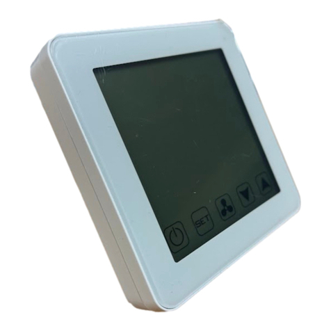
NO ICON NAME DESCRIPTION
1 Adjustment buttons For adjusting parameters, moving cursor.
2 Menu button For entering or quit menus.
3 Confirm button For confirming settings, entering manual functions.
4 Clock/Timer clock button For setting clock or timer.
5 ON/OFF button
For turn on or turn o the unit. If user turn on the
unit, the led will be lightened, and the led will be
distinguished if user turn o the unit.

• Hold down for 3 seconds
UNLOCK
• Click
• Push and hold down for 3 seconds
• Push or to select electrical element .
Icon will flash when selected
• Click to confirm
MANUAL BOOST MODE
• Press the button to turn on or o the unit
when the keyboard is unlocked.
• Some interface examples of operating, standby
and OFF standby are as follows:
POWER ON/OFF UNIT
• Hold down and and for 3 seconds
to access installation settings
• Press or to get to option 18.
Press to confirm
• 18 - Refrigerant recovery function will be
deactivated automatically after it has been
activated for 10 min
• Press or to select electrical element
Icon will flash when selected
• Press to confirm
REFRIGERANT RECOVERY
• Press buttons to switch and select Celsius
or Fahrenheit
• Press to confirm the unit setting
OTHER FUNCTION SETTINGS:
5 Disinfection
6 Holiday Away
7 OPT.Backup
8 Solar Energy
9 Hybrid
11 Smart Grid
Please note; during set-up, the |symbol will
appear when selecting settings.
TEMPERATURE UNIT SETTING

DEBUGGING FUNCTIONS INCLUDE:
15 Manual defrosting : manual defrosting function
will be deactivated automatically after defrosting
18 Refrigerant Recovery : Refrigerant recover
function will be deactivated automatically after
it has been activated for 10 minutes
19 Power Consumption Estimation
20 Operating time statistics
The interface examples of manual defrosting are
as follows:
DEBUGGING FUNCTION
The code displayed in the timer section of the
control panel means Trdh (restart oset temperature
for DHW mode ((Domestic Hot Water)) the value also
displays at the Temp section of the control panel.
• Press to enter the operating mode selecting
interface
• Press buttons to select operating mode
• Press button to confirm and return to main
interface
• Hold button for 3 sec, to set up detail
parameters in the selected mode
• Press buttons to set restart oset
temperature
• Press button to confirm and return to main
interface
The interface examples of setting is as follows:
OPERATING MODE SETTINGS
• Hold down and for 3 seconds
• There are 3 optional types of Timer Settings:
- Point Timer (default)
- Period Timer
- Appointment Timer
• or will be lightened respectively based on
timer functions
TIMER SETTINGS
Point timer setting has 4-point timer types. Each timer
includes the point clock, ON/OFF, The operating
mode and target temperature. The Controller will
then execute the setting action at each time interval.
• Press the button to enter timer setting
• Press buttons to select number to be set
(slowly flash)
• Press the button to enter the parameter settings
• Set the clock of the timer by pressing
buttons as the clock settings
•
Press the button to enter operating mode setting
• Press buttons to select operating mode
• Press
button to confirm operating mode
• If the system is in OFF mode ( ), Press
button to confirm settings and activate the point
timer settings.
• If the system is not in OFF mode ( ),
Press buttons to set target temperature
Hold the button to cancel the selected timer
The following are examples in order: No. 1 timer on,
No. 2 timer o, No. 3 timer not activated
POINT TIMER SETTING

Period timer setting has 4 period timers in this setting.
Each Timer includes; the on/o clock, operating
mode, target temperature. The Controller will then
execute the setting action at each time interval.
• Press the button to enter timer setting.
• Press buttons to select number to be set
(slowly flash)
•
Press the button to enter the parameter settings
• The will light up and will be non-active.
Press the buttons to set the ON clock
• Press the button to enter the OFF clock ( )
settings
• The will light up and will be non-active.
Press the buttons to set the o clock
• Press button to enter operating mode setting
– both and will be non-active
• Press the buttons to select operating mode
• Press buttons to confirm operating mode
• Press buttons to set target temperature
• Press button to confirm settings, and activate
the period timer.
Hold the button to cancel the selected timer
PERIOD TIMER SETTING
• Unlock the control panel and press and hold the
button for 2-3 seconds
• Press the buttons to set year
(only displays tens and single digits)
• Press button to confirm year
• Press the buttons to set the month
(at first 2 digits of )
• Press button to switch between year, month,
day
• Press button to confirm month
• Press buttons to set day
(at the last 2 digits of )
• Press button to confirm day
• Press buttons to set hour
(at first 2 digits of )
• Press button to confirm hour
• Press buttons to set minutes
(at last 2 digits of )
• Press button to confirm minute
• Press button to confirm new time settings
TIMER FUNCTIONALITY
Appointment timer setting has 4 appointment timers.
Every timer includes the appointment start clock,
appointment end clock, operating mode, target
temperature. Controller will calculate the suitable
operating time to ensure that the unit could heat the
water temperature up to the target value before the
appointment start clock.
• Press the button to enter timer setting.
• Press buttons to select number to be set
(slowly flash)
• Press the button to enter the parameter settings
• The will light up and will be non-active.
Press the buttons to set the Start clock
• Press the button to enter the end clock settings
• The will light up and will be non-active
Press the buttons to set the end clock
• Press the
button to enter operating mode
setting. Both and will be non-active.
• Press the buttons to select operating mode
• Press
button to confirm the operating mode
• Press buttons to set target temperature
• Press
button to confirm settings and activate
this appointment timer.
Hold the button to cancel the selected timer
APPOINTMENT TIMER SETTING

Holiday away parameter is the operating mode that
can be set to or mode during a “holiday”
period or when the unit is not in use. If set to
mode; the unit will be turned o during this holiday
period. If set to , the unit will heat to 25 degrees
automatically by the controller to stop any freezing (in
colder climates).
• Open Function selection interface (see previous
Function activation and Parameters when holiday
away icon is selected. Hold the
for 3 seconds
to enter holiday settings.
• Press the buttons to set operating mode
( or )
• Press the buttons to set the amount of time
away
• Press
button to confirm the mode setting
HOLIDAY AWAY PARAMETER SETTING
O-Peak Timer (OPT.Backup) Parameter is a time of
o-peak signal from the Electricity Grid (Distribution
Network Company). During the settings process, the
will display the time value (0~8 hours, default
8), the last 2 digits of will display “H” for hour.
• Open Function selection interface (see previous
Function activation and Parameters settings)
when O-Peak Timer is selected (flashing slowly)
Hold the
button for 3 seconds to enter O-
peak setting.
• Press the buttons to set the time of the o-
peak signal.
• Press the
button to confirm the time setting.
An interface example of o-peak timer parameter
setting is as follows:
OFF-PEAK TIMER PARAMETER SETTING
Disinfection parameters setting includes disinfection
clock, temperature, and cycle time. The clock
will display disinfection clock during the settings
process (10 Minute intervals).
The Temperature displays disinfection temperature
(55~75 Degrees, default 65) and cycle time (2~30
days, default 7 days)
• Open Function selection interface (see previous
Function activation and Parameters settings)
when Disinfection Icon is selected (flashing
slowly) Hold the
button for 3 seconds to enter
disinfection setting.
• Clock setting interface will open
• Set disinfection clock settings
• Press the buttons to set disinfection tem-
perature
• Press the
button to confirm the temperature.
• Press the buttons to set disinfection cycle
time
• Press the
button to confirm the cycle time and
finish disinfection setting.
DISINFECTION PARAMETERS SETTING
• Press the button for 3 seconds
• Function selection and activation interface will
then be opened
• The selected function will slowly flash
• Press the
button to activate or deactivate the
selected function
• The selected function will light up when activated
• Each function will have dierent parameters to
set; for example “Holiday Away” function will
require you set the amount of days away by
pressing the buttons. The Timer
section will display the amount of days you
have chosen and displays code:
• Press
button to complete
An interface example of holiday setting is as follows:
FUNCTION ACTIVATION AND
PARAMETERS SETTINGS

Solar energy Parameter is the operating mode that
can be set to increase temperature based on Solar
export. It includes the (default) and
modes. If the Set mode is , the controller will
increase the target temperature by 10 degrees
automatically when the system detects solar energy
export. If the Set mode is , the controller will
turn on the unit only when the system detects solar
energy export.
• Open Function selection interface (see previous
Function activation and Parameters settings)
when Solar Energy is selected (flashing slowly)
Hold the
button for 3 seconds to enter the
solar energy settings
• Press the UP/DOWN buttons to set the operating
mode
• Press
b
utton to confirm the operating mode
Interface examples:
SOLAR ENERGY PARAMETER SETTING
The Ambient Temperature of auto e-heating is a limit
value to determine if the e-heater and heat-pump can
operate at the same time. If the ambient temperature
is higher than or equal to TD, the unit will only start
the heat-pump at first. The e-heater will start after
the heat-pump has stopped if the water temperature
does not reach target value. This is because the heat-
pump has reached its highest water temperature
(code T5stop).
If the Ambient temperature is Lower than TD, the
unit will start the heat-pump first, then the e-heater
will start after 1 hour. This is triggered if the water
temperature is 10 degrees lower than the target
temperature.
During Setting process, displays the TD value,
and the displays code (TD)
• Press the
button for 3 seconds to enter the
manual function selection interface
• Press the
for 3 seconds if e-heater icon is
selected.
• Press the buttons to set the TD value
• Press the
button to confirm TD
Interface example:
AMBIENT TEMPERATURE OF AUTO
E-HEATING (CODE: TD)
• Press the
button for 3 seconds to enter the
manual function selection interface.
The following icons should then light up: ,
E-heating , Disinfection (depending on
the operating settings, see above)
• Press the buttons to select function, the
selected function should flash slowly
• Press the
button to activate or deactivate the
selected manual function
• If the function is activated, the function icon
should have a ; for example;
Interface examples:
MANUAL FUNCTION
Hybrid parameter is an ambient temperature operat-
ing limit (Code: T4MING). During this setting process
the will display the ambient temperature
(-14 ~ 20 degrees, default 5), and the
will display
code: . If the ambient temperature is lower than
T4MING, the heat pump will stop operating and need
to operate the boiler to continue heating water.
• Open Function selection interface (see previous
Function activation and Parameters settings)
when the Hybrid Icon is selected (flashing slowly)
Hold the
button for 3 seconds to enter the
Hybrid settings; it will then display T4MING
setting interface
• Press the UP/DOWN buttons to set the operating
mode
• Press the
button to confirm the T4MING
setting
Interface example:
HYBRID PARAMETER SETTING

No. DISPLAYED AT EXPLANATION DISPLAYED
AT
1
Fan speed gear
value (0 means fan
stopped)
Fan speed (FA)
2 Pulse value
Pulse value of EXV1
(E1)
3 Current value (A) Unit current (Co)
4 Temperature value Discharge temp. (Tp) (Tp)
5 Temperature value Suction temp. (Th) (Th)
6 Temperature value ODU heat exchanger
temp.(T3) (T3)
7 Temperature value ODU ambient temp.
(T4) (T4)
8 Temperature value Tank temp. (T5L) (T5L)
9 Temperature value
Ambient temp. of
auto
e-heating (Td)
(Td)
10 (Trdh) Restart oset temp. of
DHW mode (Trdh)
Temperature
value
11 (SGSL) Smart grid class
Class value
(0 means
no signal)
12 Power value in kWh,
don’t display “:”
Cumulative estimated
power consumption
(AP)
13
Power value in kWh. The
top two display integer,
and the last two display
decimal, and “:” means
the decimal point.
Current estimated
power consumption
of e-heater in 24
hours
(EP)
14
Power value in kWh.
The top two display
integer, and the last
two display decimal,
and “:” means the
decimal point.
Current estimated
power consumption
of heat pump in 24
hours
(HP)
15
Integer time value in
hours, don’t display
“:”
Cumulative operating
time of unit (t1)
16
Integer time value in
hours, don’t display
“:”
Cumulative operating
time of compressor (t2)
17
Integer time value in
hours, don’t display
“:”
Cumulative operating
time of e-heater (t3)
18 (EF) Clock chip state
Display code
“EF” if chip
error, else
display “--”.
19 (Er1) Historical fault
Error code20 (Er2) Historical fault
21 (Er3) Historical fault
22 (CtrL) Software version of
controller Version
number
23 (OdU) Software version of
unit
Interface examples:
QUERY DISPLAY FUNCTION
• Press the and buttons for 2-3 seconds to
query the unit operating parameters.
• During the query process, press the UP/DOWN
buttons to switch dierent parameters
• The icon will light up during the query process
• If some parameters are invalid for the unit, the
parameter will be displays as “—” or “----”
QUERY FUNCTION

WARRANTY INFORMATION
Emerald Energy Pty Ltd warrants this heat pump to the original purchaser.
Emerald Energy Pty Ltd warrants each new heat pump is free from defects in material and workmanship under normal use and service from the date of
purchase. 2 year labour warranty. 7 years warranty on the tank, and 5 years on the rest of the system. *Subject to terms and conditions.
This warranty does not cover damage resulting from accident, misuse or abuse or lack of reasonable care of the product.
In no case shall Emerald Energy Pty Ltd be liable for any incidental or consequential damages for breach of this or any other
warranty express or implied whatsoever.
For full warranty details visit our website emerald-energy.com.au
Emerald Energy Pty Ltd
ABN 86 632 172 368
2/29 Mitchell Rd Brookvale NSW 2100 2023.03
The controller will initialise after a few seconds of
power being turned on and no control commands or
button operations are pressed.
• On the Main interface, press and hold the
+ +
for 10 seconds to begin factory reset
• System will reset and turn back on with no
parameters entered.
INITIALISE AND RESTORE FACTORY
SETTINGS
If a fault occurs with the unit, an error code will be
displayed at the display and an alert icon
( ) will rapidly flash and a cancel icon ( )
will slowly flash.
CODE EXPLANATION
E2: Communication error
E4: Water tank temperature sensor error (T5L)
E5: ODU heat exchanger temperature sensor error (T3)
E6: ODU ambient temperature sensor error (T4)
E9: Suction temperature sensor error (Th)
EA: Discharge temperature sensor error (Tp)
EF: Clock chip error
(Most of the functions are OK except timer schedule without
network.)
HP: Smart Grid signal error
HC: E-heater error (Current is less than 2A when e-heater
operating)
P1: High pressure protection
P2: Over load protection of fixed compressor
P4: High discharge temperature (Tp) protection
PA: Low tank temperature protection
F2: Low super-heat of discharge protection
F6: Electric expansion valve joint fault
bA: The ambient temperature exceeds the declared range
(not an error)
db: Anti-freezing operating (not an error) for some unit
ERROR AND OTHER CODE
EXPLANATION
Other manuals for EE-HWS-RCHP-200
1
This manual suits for next models
3
Table of contents
