EMERGENT APS-500 Instruction Manual

See discussions, stats, and author profiles for this publication at: https://www.researchgate.net/publication/259657877
waste tire with steam pyrolysis machine guidelines
Data · January 2014
CITATIONS
0
READS
1,241
1 author:
Some of the authors of this publication are also working on these related projects:
tyre pyrolysis oil-carbon combined combustion for power View project
new one View project
Uladzimir Kalitko
19 PUBLICATIONS19 CITATIONS
SEE PROFILE
All content following this page was uploaded by Uladzimir Kalitko on 13 January 2014.
The user has requested enhancement of the downloaded file.

1
GUIDELINES FOR USING TНЕ STEAM
PYROLYSIS MACHINE FOR SCRAP TIRE
CONTINUOUS RECYCLING (APS-500)
By Dr.Uladzimir A.Kalitko,
GSKB Ltd Company, Brest,
Belarus, Vice-Chief Designer
Content:
1. Introduction
1.1. Objectives and advantages of the machine
2. Machine Description and Operation
2.1. Equipments, units and parts of the machine
2.2. Description on the tire steam pyrolysis process
2.3. Machine control system and panel description
3. Installation Instructions: After Shipping
4. Machine Operation Guidelines
4.1. Machine preparation for start-up
4.2. Start-up and adjusting procedure
4.3. Machine operation procedure
4.4. Handling the pyrolysis products
4.5. Machine idle operation regime
4.6. Machine shut-down procedure
4.7. Procedure of emergency stop
5. Machine Maintenance Instructions
5.1. Maintenance of the oil auto-burner
5.2. Maintenance of the reactor furnace
5.3. Maintenance of the pyrolysis reactor
5.4. Maintenance of the oil condenser
5.5. Maintenance of the steam boiler
5.6. Spares and consumed materials
6. Steam pyrolysis safety rules and warnings
7. Environmental Aspects of Steam Pyrolysis:
SO2 emission with flue gas of steam pyrolysis
8. Authorized references on steam pyrolysis
РУКОВОДСТВО ЭКСПЛУАТАЦИИ АГРЕГАТА
ДЛЯ НЕПРЕРЫВНОГО ПАРОВОГО ПИРОЛИЗА
ОТХОДОВ ИЗМЕЛЬЧЕННЫХ ШИН (АПШ-500)
В.А.Калитко, канд.технич.наук,
зам.ген.конструктора ОАО ГСКБ,
г.Брест, Республика Беларусь
Содержание:
1. Введение
1.1. Назначение и преимущества агрегата
2. Описание устройства и работы агрегата
2.1. Оборудование и составные части агрегата
2.2. Описание процесса парового пиролиза шин
2.3. Описание системы и панели регулирования
3. Указания по монтажу после поставки
4. Руководство по эксплуатации агрегата
4.1. Подготовка к запуску агрегата
4.2. Порядок запуска и настройки
4.3. Порядок эксплуатации агрегата
4.4. Обработка продуктов пиролиза
4.5. Режим холостого хода агрегата
4.6. Порядок остановки агрегата
4.7. Порядок экстренной остановки
5. Техническое обслуживание агрегата
5.1. Техническое обслуживание горелки
5.2. Техническое обслуживание топки
5.3. Техническое обслуживание реактора
5.4. Обслуживание конденсатора топлива
5.5. Техническое обслуживание пар. котла
5.6. Запасные части и расходные материалы
6. Меры безопасности при паровом пиролизе
7. Экологические аспекты парового пиролиза:
содержание SO2 в отходящих топочных газах
8. Публикации автора по паровому пиролизу

2
1. Introduction
1.1. Objectives and advantages of the machine
The objectives of steam pyrolysis machine APS-500
(GSKB Ltd) are to perform the continue pyrolysis
processing of max 500 kg/h scrap tire for recycling
not less 40% the oil and 35% carbon char by-pro-
ducts from that, provided these to be commercial
quality such as the oil flash point temp not bellow
60oC and oily residual matters in the char not above
1% which is usually 35-40oC and 5-7% correspond-
ingly s for tire pyrolysis without steam.
Combustible pyrolysis off-gas is residual after oil
condensed and is afterburning for heating the pyro-
lysis reactor and merely a little of the oil fuel is re-
quired for lighting (igniting) the gas combustion at
the high temperature 950-1000oC so to burn out all
of the hazardous aromatic components in such of
tire pyrolysis gas, so resulting in the processing is
both beneficial for people and the environment.
Also the steam pyrolysis method provides rather of
processing explosion safety, being the pyrolysis gas
diluted with steam so as its explosion concentration
with air is reduced by steam as an inert agent.
Steam is generating in a boiler of exhaust heat type
by utilizing the flue gas enthalpy after heating the
pyrolysis reactor and is injecting into that for clean-
ing the carbon char against of oil-tire residual mat-
ters above, provided the steam is preliminary super-
heated up to the same of tire pyrolysis temperature
400-450oC along with heating the same reactor too.
The machine is well capable for idle operation at the
furnace controlled temperature 850-900oC with any
mechanical stop of tire loading when steam is gene-
rating but not injecting into reactor and automati-
cally draining to outside so to save the furnace tem-
perature. When tire loading is renewed the tempe-
rature regime of machine is automatically restored
in soon as max 30 minutes.
Additionally to the quality and safety effects with
steam as introduced above the steam jet at the
boiler pressure max 5 bar is used for spray cooling
with evaporating water at 100oC in the oil con-
denser of a new venturi type where steam is also
acting for cleaning against of a carbon soot con-
tamination that is a usual defect of any surface con-
denser type with tire pyrolysis. Also, being diluted
with steam like with a carrier agent, the pyrolysis
gas is not-saturated with oil matters so as it is piping
from reactor to condenser with much less of soot
contamination then usually.
1. Введение
1.1. Назначение и преимущества агрегата
Агрегат парового пиролиза АПШ-500 (ОАО ГСКБ)
предназначен для непрерывной утилизации до
500 кг/ч шин с получением из них не менее 40%
жидкого топлива и 35% углеродного остатка при
их потребительском качестве не менее 60oC для
температуры вспышки топлива и не более 1% со-
держания топливных фракций в углеродном ос-
татке, что при пиролизе шин без пара обычно
составляет 35-40oC и 5-7% соответственно.
Остаточный горючий газ после конденсации то-
плива дожигается для нагрева реактора пироли-
за и только немного топлива требуется для под-
светки (поддержки) высокотемпературного горе-
ния газа при 950-1000oC так, чтобы выжечь все
его вредные ароматические компоненты при пи-
ролизе шин, обеспечивая как экономичность, так
и экологичность переработки. Наряду с этим па-
ровой пиролиз обеспечивает и взрывобезопас-
ность пиролизного газа тем, что пар как инерт-
ный агент разбавляет и снижает его взрывоопас-
ную концентрацию с воздухом.
Пар вырабатывается в котле-утилизаторе за счет
тепла топочных газов после нагрева реактора пи-
ролиза и подается в него же для паровой очистки
углеродного остатка от топливных фракций, как
указано выше, причем предварительно пар пере-
гревается до температуры пиролиза шин 400-
450oC вместе с нагревом самого реактора.
Агрегат может находиться и в холостом режиме с
авторегулированием температуры 850-900oC при
механической остановке загрузки шин, когда вы-
рабатываемый пар вместо подачи в реактор дре-
нируется в атмосферу, чтобы сохранить темпера-
туру топки. При возобновлении загрузки темпе-
ратурный режим переработки автоматически во-
станавливается в течение до 30 минут.
Дополнительно к указанной эффективности пара
по качеству и безопасности пиролиза струя пара
под давлением до 5 бар используется для испа-
рительного впрыска охлаждающей воды в кон-
денсаторе топлива типа вентури, обеспечивая
при этом его очистку от загрязнения сажей, что
при пиролизе шин характерно для всех других
конденсаторов поверхностного типа. Кроме того,
в смеси с паром пиролизный газ менее насыщен
углеводородами и его газоход от реактора к кон-
денсатору также гораздо меньше загрязняется
сажей, чем обычно.

3
2. Machine Description and Operation
2.1. Equipments, units and parts of the machine
The machine is consisted of the next equipments
and units as shown in the picture and PID-diagram
of the machine (Fig.1-2), where the control system
tools and lines are marked by red color:
1 – standard oil auto-burner for starting-up,
1A – furnace (inside the reactor hot box),
2 – triple-passing auger pyrolysis reactor,
3 – steam boiler of exhaust heat type,
4 – oil condenser of venturi type,
5 – oil cooler of pack water tube type,
6 – char screw with a cooling water jacket,
7 – sectionalized exhaust stack,
8 – boiler water supply tank,
9 – double-gate valves of pneumatic type
10 – air compressor for the valves 9 above,
11- exhaust smoke fan,
12 – manual disk valve for gas jacket in venturi,
13 – pyrolysis residual off-gas blower,
14 – air blower for gas afterburning ,
15 – boiler water pump,
16 – manual disk valve for pyrogas accident exit,
17 – steam control auto-draining valve to outside,
18 – water control spraying valve to oil condenser,
19 – start fuel tank for oil burner,
20 – pyrolysis oil interim tank,
21 – steam-water piping & valves,
22 – machine control panel box.
2. Описание устройства и работы агрегата
2.1. Оборудование и составные части агрегата
Оборудование агрегата включает следующие пози-
ции, как показано на общем виде и функциональ-
ной схеме (Рис.1-2), где элементы системы контро-
ля и автоматики выделены красным цветом:
1 – пусковая горелка на ж/топливе,
1А – топка (в термоблоке реактора),
2 – трех-шнековый реактор пиролиза,
3 – паровой котел-утилизатор,
4 – конденсатор топлива типа Вентури,
5 - водотрубный охладитель топлива,
6 – водоохлаждаемый шнек выгрузки,
7 – составная дымовая труба,
8 – питательный бак котла,
9 – клапаны двойной загрузки-выгрузки
10 – компрессор для пневмоклапанов 9,
11 – дымосос топочных газов,
12 – диск-заслонка для газовой рубашки вентури,
13 – вентилятор остаточного пирогаза,
14 – вентилятор воздуха на дожигание пирогаза,
15 – насос питательной воды котла,
16 – аварийная заслонка для выброса пирогаза,
17 – клапан для регулируемого сброса пара,
18 – клапан для впрыска воды в конденсатор,
19 – топливный бак пусковой горелки,
20 – сливной бак пиролизного топлива,
21 – паро-водопроводы с арматурой,
22 – шкаф-пульт управления агрегата.

4
Fig.1. 3D model design view of the steam-auger pyrolysis machine per 500 kg/hr waste tire recycling
Рис.1. Общий вид 3D модели агрегата парошнековой пиролизной переработки шин на 500 кг/ч

5
Fig.1A. The machine side view with both operating areas for both of oil and carbon char discharge (view A)
Рис.1А. Вид агрегата с обеих сторон обзора выгрузки топлива и углеродного остатка пиролиза (вид А)

6
Fig.1B. The machine another side view (from the side of pyrolysis oil discharge to the tank 20)
Рис.1В. Общий вид агрегата с другой стороны (со стороны слива ж/топлива в емкость 20)

7
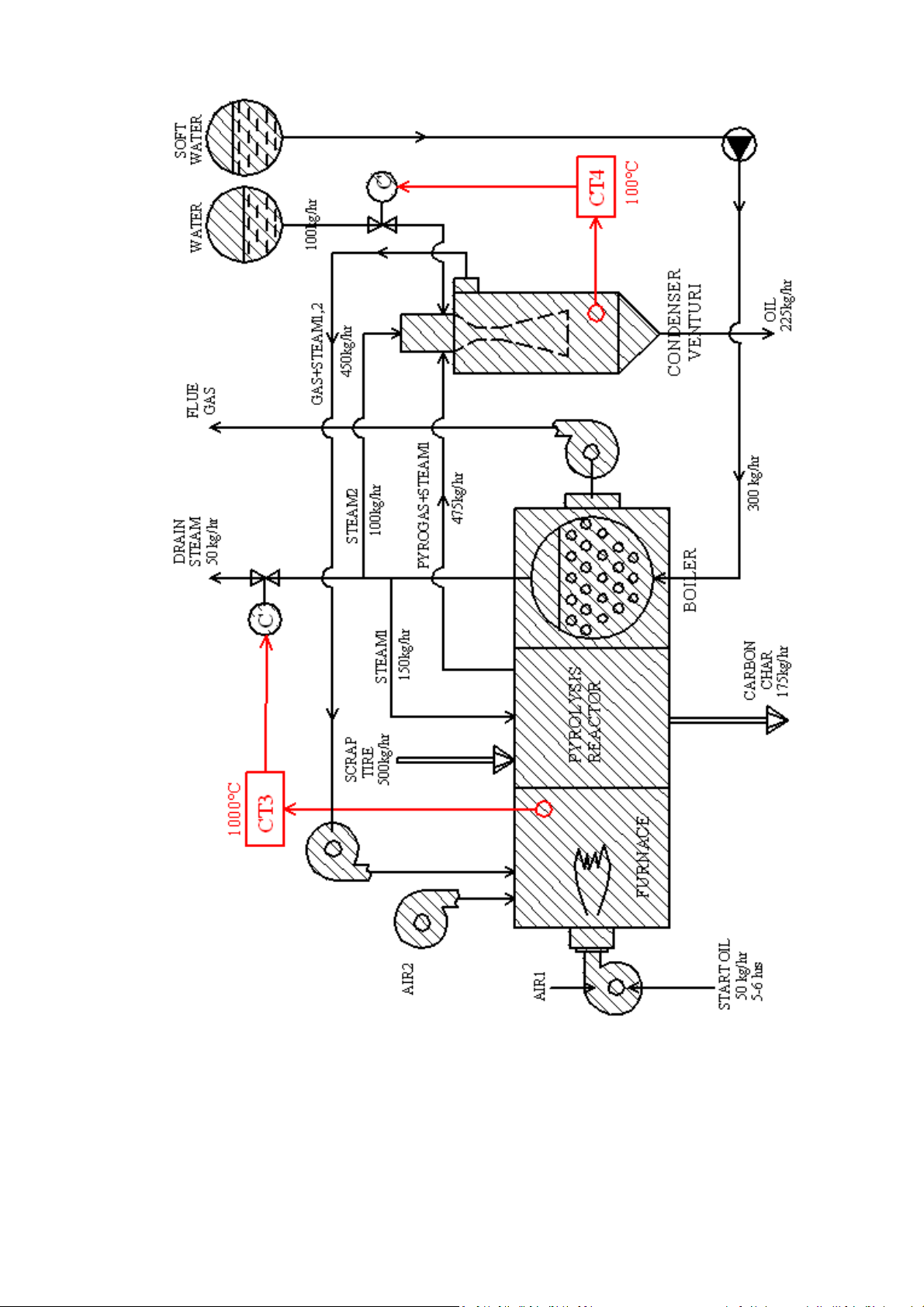
Fig.2. Process Instrumentation Diagram of SPM-500 machine (control system lines shown in red color)
Рис.2. Функциональная схема процесса и оборудования АПП-500 (автоматика показана красным)
8
Fig.3. Process Flow Sheet of the steam pyrolysis machine: temp controllers CT3-CT4 are shown in red
color; water flow rate as max 1.5 m3/hr for cooling both of carbon char and pyrolysis oil is not shown
Рис.3. Схема потоков агрегата парового пиролиза: регуляторы температуры СТ3-СТ4 показаны
красным цветом; расход воды 1.5 м3/ч на охлаждение выгрузки углерода и топлива не показан

9
2.2. Description of the tire steam pyrolysis process
The machine is loading with max 500 kg/hr scrap ti-
re by means of conveyor supply system of the cus-
tomer, doing that through the double flap-gate pne-
umatic valves 9 operated as the airlock of pyrolysis
reactor 2 (see Fig.2). While the conveyor system is
operating continually the valves operate periodically
as alternately one by other as max 6 cycles/min by
which way the scrap tire is periodically accumulated
in hopper and next fallen down by valves. Tires must
be shredded for standard size of 50x50 mm, allow-
ing so much as ±20 mm deviation of that.
Reactor is installed inside the same hot box like the
furnace 1А but at the side of that so to separate
their thermal condition, being the box made of cast-
able refractory lining. By the operating length L=4 m
of the triple-pass auger reactor it is not less then 15
minutes of tire processing time with its heating up
to pyrolysis temperature 400-450oC under the reac-
tor heating temp 800-850oC while the furnace oper-
ating temp is to be 950-1000oC. Provided with mo-
tor (M7-14) 5.5 kW, the auger rotary speed is max
2.5 rpm, being that adjusted manually by the fre-
quency inverter (UZ2-14).
The carbon char is discharged from reactor through
the same type of valves 9 by means of the bottom
auger 6 provided with a cooling water jacket to de-
crease the carbon exit temperature to 50-60oC for
its handling next by the customer. Steam is injected
into reactor at the discharge area so to provide cle-
aning the carbon char as mentioned initially, doing
that by way of multi-jet cross injection in amount of
25-30% tire loading rate that is also acting like a ste-
am curtain against of air leakage into reactor addi-
tionally to the valves 9. To correspond the pyrolysis
thermal regime with steam injecting into reactor it is
superheating up to near the same temperature 400-
450oC, doing that in a tube coil around and along
with heating the same reactor.
With steam the pyrolysis gas is not saturated with
oil matters and therefore not condensable with pip-
ing as it is usual for tire pyrolysis without steam. In
our case the gas is piping from the reactor 2 under
action of steam ejecting effect in the oil condenser 4
of a new venturi type where steam jet is acting for
spraying the cooling water in amount approx 20% of
tire processing rate which is all evaporated at 100oC
while the pyrolysis gas is condensed at the same
temperature. By the steam jet it is a self-cleaning
effect against of carbon soot as all noticed initially.
2.2. Описание процесса парового пиролиза шин
Загрузка агрегата до 500 кг/ч производится от кон-
вейерной системы заказчика через двойные откид-
ные пневмоклапаны 9, действующие как затворы
от поступления воздуха в трехходовой реактор пи-
ролиза 2 (см.Рис.2). При постоянной подаче кон-
вейера клапаны работают циклично один за дру-
гим до 6 цикл/мин так, что дробленый скрап шин
периодично накапливается в бункере и затем про-
валивается через клапаны. Шины должны быть из-
мельчены до стандартного размера 50х50 мм при
возможном отклонении этой величины до ±20 мм.
Реактор расположен в том же термоблоке c залив-
ной футеровкой, что и топка 1А, но сбоку от нее,
чтобы разделить их термические условия. Рабочая
длина L=4 м трехходового шнек-реактора обеспе-
чивает не менее 15 минут времени нагрева шин до
температуры пиролиза 400-450oC при температуре
греющих реактор топочных газов 800-850oC и ра-
бочей температуре в топке в пределах 950-1000oC.
При мощности двигателя-редуктора (М7-14) до 5.5
kW скорость шнеков реактора до 2.5 об/мин наст-
раивается вручную частотным регулятором-преоб-
разователем (UZ2-14).
Углеродный остаток шин выгружается из реактора
через такие же двойные клапаны 9 и шнек 6 снизу,
оборудованный водяной рубашкой для охлажде-
ния выгрузки до 50-60oC, чтобы заказчик мог обра-
щаться с ним далее. Пар подается в реактор в зоне
выгрузки так, чтобы обеспечить чистоту углеродно-
го продукта, указанную в самом начале, что дела-
ется путем многоструйного поперечного потока в
количестве 25-30% от загрузки шин и действует как
паровая завеса от воздуха дополнительно к клапа-
нам 9. Чтобы соответствовать термическому ре-
жиму пиролиза, перед этим пар перегревается
примерно до той же температуры 400-450oC, что
делается в трубном змеевике вдоль и вокруг само-
го реактора и вместе с его нагревом.
В смеси с паром пиролизный газ не насыщен пара-
ми топлива и потому не так конденсируется в тру-
бопроводе, как это имеет место при пиролизе шин
без пара. В нашем случае газ поступает из реактора
2 в конденсатор 4 под действием эжектирующей
струи пара в нем для впрыска охлаждающей воды
в количестве примерно 20% от загрузки шин, кото-
рая вся испаряется при 100oC в то время, как пиро-
газ конденсируется при этой же температуре. Эта
же струя пара дает эффект самоочистки конденса-
тора от сажи, как это все указано вначале.
The condenser is made of a double-shell type and Двойная оболочка конденсатора выполнена в виде

10
provided with a hot gas jacket to prevent the shell
against of cooling bellow 100oC from outside so as
to prevent any water by steam condensing at the
shell. The jacket is heating by flue gas after the
boiler at the temp 200-250oC which flow rate is ad-
justed manually by disk valve 12 so as some of the
flow from the boiler 3 to stack 7 is directed via the
condenser gas jacket as required.
Condensed oil is flowing by itself to the bottom in-
terim tank 20 so as it is air hydraulic lock of the con-
denser 4. Along with that oil is cooling in the heat
exchanger 5 of a bundle water-tube type to low the
oil temperature from 100oC to near 50oC for its next
handling as considered in p.4.4 next bellow.
Combustible residual pyrolysis off-gas after oil con-
densing is piping from venturi by means of the gas
blower 13 for its afterburning in the reactor furnace
1A at the temperature 950-1000oC as it is noticed
initially, being that minimally assisted by the oil
burner 1 as for lighting (igniting) the off-gas merely
that is required by reason of a low-calorific value of
the gas because of all used steam after its injection
into condenser and reactor is residually mixed with
off-gas. Combusting air is provided by the blower 14
that is manually adjusted preliminary as required by
means of the frequency electronic inverter (UZ1-5)
as considered in p.2.3 bellow.
Steam is generating in the exhaust heat boiler 3 by
GSKB Ltd design that is proved by Certificate of Rus-
sia No.238-08-2.7.1 of 29.12.2009 (see on website
www.gskb.by) and corresponded to the safety stan-
dards of Russia 10-574-03 No.88 of 11.06.2003. The
boiler is heated by flue gas flow after heating the
pyrolysis reactor 2 and supplied with soft water
from the tank 8 by means of water pump 15 with a
water check valve 21, being all of that typically con-
trolled by the water level controllers (SL1-6) and
(SL2-10) in the boiler and tank correspondingly. The
soft water supply to the tank is to be provided by
the customer.
Flue gas is piping through the reactor and boiler to
the stack 7 by means of the smoke fan 11 which mo-
tor (M6-15) is controlled by the frequency electronic
inverter (UZ3-15) as considered in p.2.3. There are
controlled air injections with flue gas piping so to
reduce the flow temperature from 950-1000oC to
800-850oC for heating the pyrolysis reactor (air in-
jection point A3 in furnace) and from 650-700oC to
450-500oC for heating the boiler and steam generat-
ing so much as required exactly for processing, not
more (injection point A4 in boiler) as it is shown
газовой рубашки, чтобы не допустить его охлажде-
ние снаружи менее 100oC и тем самым предотвра-
тить воду от конденсации пара на стенках. Рубашка
греется отходящими топочными газами после кот-
ла при температуре 200-250oC и их расход устанав-
ливается вручную дисковой заслонкой 12 так, что
часть топочных газов из котла 3 в трубу 7 проходит
сколько требуется через эту газовую рубашку.
Конденсированное топливо самотеком поступает в
нижний бак 20 так, что этот бак является гидравли-
ческим затвором конденсатора 4 от воздуха. При
этом в водотрубном теплообменнике 5 топливо ох-
лаждается от 100oC до примерно 50oC для его об-
работки заказчиком далее, как указано в п.4.4.
После конденсации топлива остаточный горючий
пирогаз вентилятором 13 подается из конденсато-
ра в топку 1А на дожигание при температуре 950-
1000oC, как указано вначале, что поддерживается
горелкой 1 с минимальным расходом топлива не
более чем для подсветки (поджига) пирогаза, что
требуется из-за низкой калорийности остаточного
пирогаза в смеси с отработанным паром после его
подачи в реактор и конденсатор. Воздух на дожи-
гание пирогаза подается вентилятором 14, кото-
рый для этого предварительно настраивается час-
тотным регулятором мощности (UZ1-5), как это
рассмотрено ниже в п.2.3.
Пар вырабатывается в котле-утилизаторе 3 конст-
рукции ОАО ГСКБ, имеющем сертификат РФ №
238-08-2.7.1 от 29.12.2009 (см. сайт www.gskb.by) и
соответствующем правилам безопасности РФ ПБ
10-574-03 № 88 от 11.06.2003 для котлов данного
типа. Котел работает на отходящих топочных газах
после реактора 2. Котел питается химически мяг-
кой водой из бака 8 под действием насоса 15 с об-
ратным клапаном 21, что, как обычно, стандарт-
ным образом контролируется датчиками уровня
воды (SL1-6) и (SL2-10) в котле и баке соответст-
венно. Подача мягкой котельной воды в бак про-
изводится заказчиком.
Через реактор и котел-утилизатор топочные газы
направляются в дымовую трубу 7 дымососом 11,
мощность которого (M6-15) регулируется частот-
ным преобразователем (UZ3-15), как рассмотрено
ниже в п.2.3. При этом производятся контролиру-
емые подсосы воздуха для снижения температуры
от 950-1000oC до 800-850oC для нагрева реактора
пиролиза (подсос воздуха А3 в топке) и примерно
от 650-700oC до 450-500oC для котла-утилизатора и
выработки пара не более того, как требуется для
процесса (подсос воздуха А4 в котле), как схема-
11
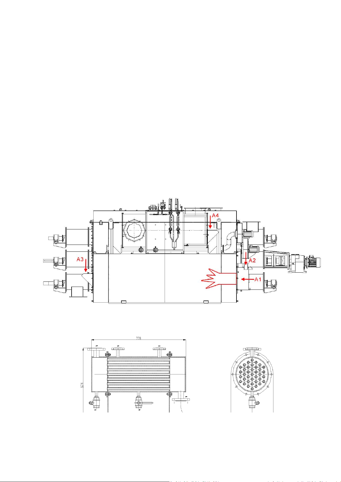
schematically in Fig.4. In connection with that the
air supply designed as A1 and A2 is provided corre-
spondingly by the oil auto-burner 1 and air blower
14 as noticed above.
The machine control system is equipped with the
steam and water automatic valves 17 and 18 corre-
spondingly which function and operation is consid-
ered in p.2.3 just bellow. The manual disk valve 16
installed on the pyrolysis gas pipeline to outside is
normally closed as proposed only for gas emergency
exit that is considered bellow in p.4.7. There are also
manual ball-valves at steam- and water pipelines of
the machine as shown but not numbered which are
used for operation as considered next in 4.2 and 4.5.
The pictures of the valves and other standard equip-
ments of the machine (oil-water cooler, oil burner,
double flap-gate pneumatic valves, frequency elec-
tronic invertors of motors, steam and water flow
meters of rotary-gear type) are shown in Figs.5-11.
тично показано на Рис.4. В этой связи подача воз-
духа под индексами А1 и А2 производится соот-
ветственно от вентилятора топливной горелки 1 и
указанного выше вентилятора 14.
Система автоматики агрегата включает регулирую-
щие клапаны воды и пара 17 и 18 соответственно,
функции и действие которых рассмотрено в п.2.3
ниже. Ручная поворотная заслонка 16 на линии вы-
броса пирогаза в атмосферу является нормально
закрытой и предназначена только для аварийного
случая, как указано в п.4.7 далее. Имеющиеся руч-
ные запорные клапаны на паро- и водопроводах
агрегата показаны без нумерации и используются
согласно руководству в п.п. 4.2 и 4.5. Общие виды
клапанов, а также другого оборудования агрегата
(охладитель топлива, топливная горелка, двойные
откидные пневмоклапаны загрузки-выгрузки, час-
тотные регуляторы двигателей, ротационные рас-
ходомеры воды и пара) приведены на Рис.5-11.
Fig.4. Arrangement of the air supply and injection A1-A3 (all shown in red color) through the SPM-500
Рис.4. Места подачи и подсосов воздуха А1-А4 (показаны красным цветом) на агрегате АПП-500
Fig.5. Heat exchanger of usual shell-blunder tube type for water cooling of pyrolysis oil
Рис.5. Типовой кожухотрубный теплообменник для водяного охлаждения топлива

12
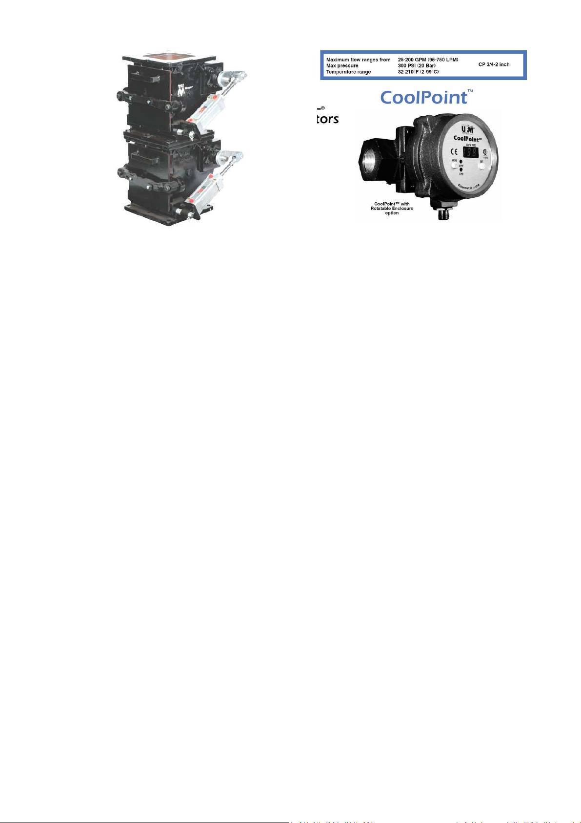
Fig.6.The typical steam and water control valves (3/4’’ size) with a driving motor of flange type
Рис.6. Регулирующие клапаны пара и воды (размер Ду20) с фланцевым электроприводом
Fig.7. The manual ball-valves of screw joint type
Рис.7. Ручной шаровой кран резьбового типа
Fig.8. The typical AC-motor frequency driver
with a removable keypad (shown at the left)
Рис.8. Частотный регулятор мощности со
съемной цифровой панелью управления
Fig.9. Typical oil fuel auto-burner VL 4.460-610 DP
with a digital temp controller 20 inside the case 18
operated with a triple-stage heat capacity control
Рис.9. Топливная горелка типа VL 4.460-610 DP
с цифровым дисплеем 20 на кожухе панели 18,
работающая с 3-позиционным регулированием
13
Fig.10. Typical double flap gate pneumatic valves
Рис.10 Двойные пневмоклапаны откидного типа
Fig.11. Typical rotary-gear flow meter of shedding type
Рис.11. Роторный счетчик-расходомер со сбросом
2.3. Machine control system and panel description
2.3.1. Equipment of the machine control system
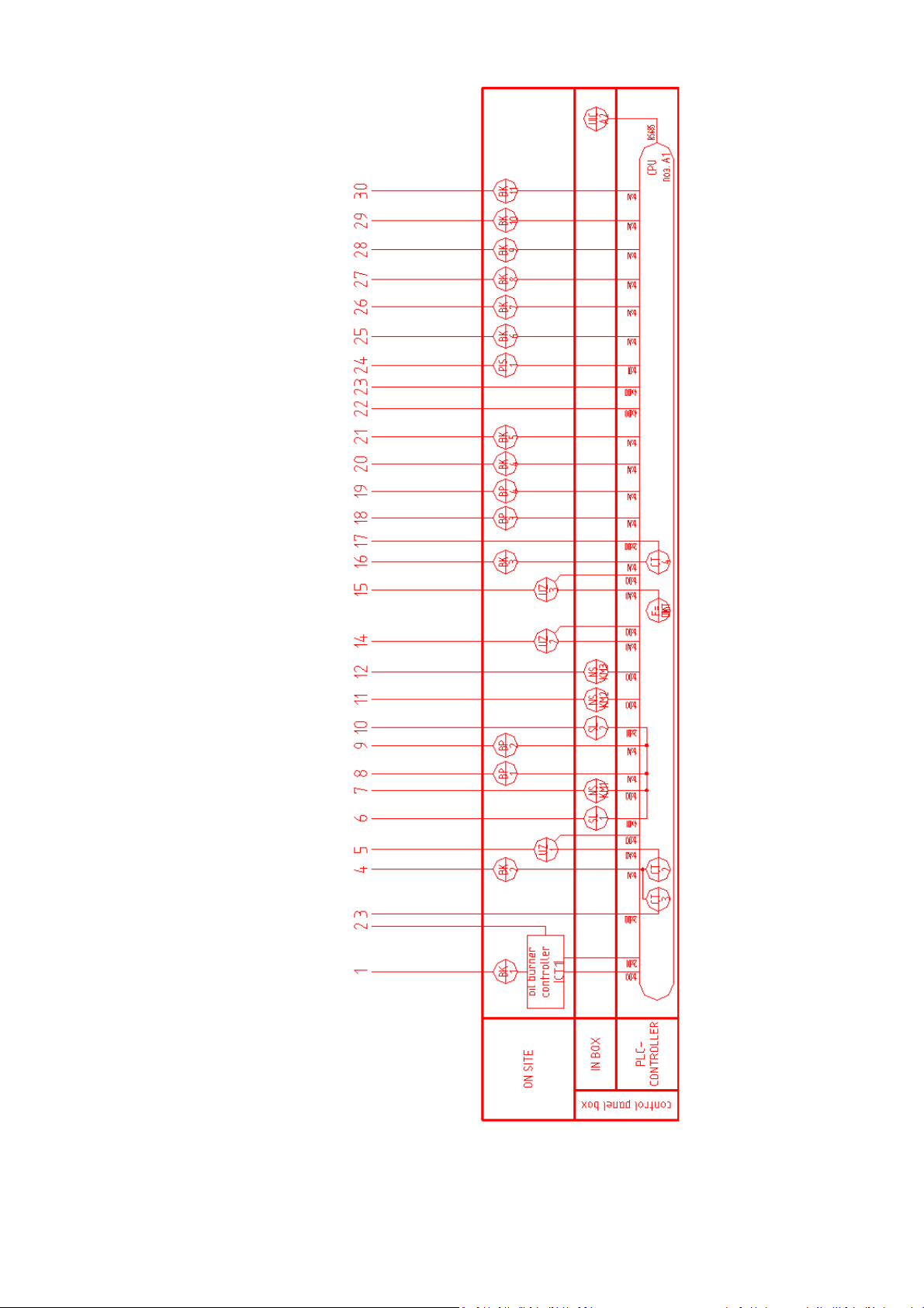
As shown in the functional diagram of the machine
control system (Fig.12) where the wiring line num-
bers (in red) are corresponded to the lines in Fig.2, it
includes the next sensors, tools and valves installed
both on site and control box of the machine:
CT1 – digital controller installed inside oil auto-burner,
CT2…CT4– control programs in PLC-processor of machine,
BK1…BK12 – temperature sensors of analog signal type,
BP1…BP2 – low-pressure sensors of digital signal type,
SL1, SL2 – water level sensors of contact-electrode type,
M1…M8 – electric motors of driving valves and others,
UZ1…UZ3 – frequency electronic invertors of motors,
NS(KM1…KM3) – motor starters of electromagnetic type,
CPU-A1 – PLC-processor of the machine control system,
UIC-A2 – screen monitor panel of sensor-touched type,
P1 – steam pressure manometer of gage-pressure type,
P1S – steam pressure manometer of electric contact type,
F1…F3 – steam and water flow meters of rotary gear type
BE1, BE2 – steam and water control valves (17-18 above),
YA1, YA2 – driving solenoid valves for pneumatic valves 9.
2.3. Описание системы и панели регулирования
2.3.1. Состав системы контроля и регулирования
Как показано на функциональной схеме автоматики
(Рис.12), где линии подключений (красные) соответ-
ствуют линиям на Рис.2, система регулирования аг-
регата включает следующие датчики, клапаны и др.
элементы по месту и на пульте управления агрегата:
CT1 – электронный регулятор топливной горелки,
CT2…CT4 – регулирующие программы PLC-процессора,
BK1…BK12 – датчики температуры аналогового типа,
BP1…BP2 – электронно-цифровые датчики разрежения,
SL1, SL2 –датчики уровня воды электродного типа,
M1…M8 – двигатели исполнительных механизмов,
UZ1…UZ3 – электронные преобразователи частоты,
NS(KM1…KM3) – пускатели электромагнитные,
CPU-A1 – общий программный PLC-процессор,
UIC-A2 – графическая сенсорная панель управления,
P1 – показывающий манометр общего назначения,
P1S – электроконтактный манометр давления пара,
F1…F3 – ротационные расходомеры пара и воды,
BE1, BE2 – регулирующие клапаны воды и пара (17-18),
YA1, YA2 – соленоидные вентили для пневмоклапанов 9.
14
Fig.12. The functional diagram of control system and control panel of the machine
Рис.12. Функциональная схема автоматики и панели регулирования агрегата

15
2.3.2. The furnace triple-temp control mode
The triple-temp control mode Т1-Т3 is performed in
the furnace 1А (see in Fig.2) so to control its prehe-
ating temperature with oil burner (i), to control the
temp condition for combusting air to be automati-
cally supplied for pyrolysis off-gas afterburning with
tire loading and processing after the preheating
stage (ii), or otherwise for air to be automatically
stopped if no loading, and to control the off-gas bur-
ning temperature with steam used for processing
(iii), including the transition between them to be
performed and controlled automatically too. With
reference to designation in Fig.2-3 and Fig.12-13 it is
controlled by the way as considered here bellow:
i) Тhe first temp control mode is carried out typically
and automatically with preheating the furnace up to
the temp T1= 850-900oC by means of the typical oil
auto-burner 1 such as VL 4.460-610 DP of 0.6 MW
heat capacity, being that performed by the temp
sensor BK1 and digital controller CT1 installed in the
burner (see Fig.9) and operated in a triple-step con-
trol mode by around 20:60:100% capacity provided
with combination of two fuel nozzles at both level of
oil operating pressure by oil pump of the burner.
When the temp Т1=850-900oC is achieved the bur-
ner is operated by variable capacity 60/100% as
shown in the furnace temp diagram (Fig.12) and oil
pressure is automatically varied by the oil pump as
above. Combusting air A1 for oil fuel burning is typi-
cally provided by air blower installed in the burner.
ii) The next temp control mode is performed auto-
matically by the temp sensor BK2 and controller CT2
that is logically programmed in PLC-processor of the
machine with function to turn-on the air blower 14
for combusting air A2 supply when the furnace tem-
perature is increasing next up to T2=925±10oC. The
reactor is loading with scrap tire, the gas fan 14 is
operating automatically with reactor too and pyroly-
sis off-gas is afterburning initially just with an exces-
sive air A1. It is not enough and combusting air A2 is
supplied by the controller CT2, being adjusted pre-
liminary and manually by the frequency electronic
inverter UZ1 as considered next in p.4.2.
iii) The third temp control mode is performed auto-
matically by the same sensor BK2 and controller CT3
programmed in PLC-processor of machine with func-
tion to control the furnace operating temperature
T3=950-1000oC when reactor is loading with scrap
tire and off-gas is afterburning with all of used
steam together. The control is performed by way of
steam less/more draining to outside, doing that di-
2.3.2. Тройное регулирование температуры топки
Автоматика тройного регулирования температуры
Т1-Т3 в топке 1А (см. Рис.2) обеспечивает контроль
ее предварительного нагрева топливной горелкой
(i), автоматическую подачу воздуха на дожигание
пирогаза при загрузке шин после предварительно-
го нагрева (ii), или наоборот автоматически отклю-
чает подачу этого воздуха, если загрузка шин оста-
новлена, а также регулирует температуру дожига-
ния пирогаза с отработанным паром в процессе
загрузки и переработки (iii), включая и контроль
переходного состояния между загрузкой и оста-
новкой. Со ссылкой на обозначения Рис.2-3 и Рис.
12-13 это осуществляется следующим образом:
i) Вначале осуществляется типовое регулирование
температуры предварительного нагрева топки до
T1= 850-900oC блочно-автоматической топливной
горелкой 1 типа VL 4.460-610 DP мощностью до 0.6
MW, что производится датчиком температуры ВК1
и встроенным электронным регулятором горелки
СТ1 (см.рис.9) в 3-позиционном режиме регулиро-
вания примерно на 20:60:100% мощности, что обе-
спечивается комбинацией двух топливных сопел
на двух рабочих уровнях давления топливного на-
соса горелки. После нагрева до T1=850-900oC она
работает с переменной мощностью 60/100%, как
показано на температурной диаграмме (Рис.12),
от переменного давления топлива, как указано
выше. Первичный воздух на горение топлива А1
подается вентилятором горелки.
ii) Далее контроль температуры осуществляется
датчиком ВК2 и регулирующей программой СТ2 в
сети общего PLC-процессора с функцией включе-
ния вентилятора 14 вторичного воздуха А2, когда
температура топки повышается до T2=925±10oC. К
этому времени реактор загружен шинами, венти-
лятор пирогаза 13 включен вместе с реактором и
дожигание пирогаза происходит только на избыт-
ке первичного воздуха от горелки А1. Этого недос-
таточно и программа СТ2 включает вентилятор
воздуха 14, расход которого настраивается пред-
варительно вручную частотным регулятором UZ1
как это указано в п.4.2 далее.
iii) Третий уровень контроля осуществляется от то-
го же датчика ВК2 по регулирующей программе
СТ3 в сети общего PLC-процессора с функцией ав-
томатического регулирования рабочей температу-
ры топки T3=950-1000oC при загрузке реактора ши-
нами и дожигании пирогаза вместе со всем отра-
ботанным паром. Регулирование производится пу-
тем сброса меньшей/большей части пара из котла

16
rectly from the boiler through the steam control va-
lve 17 that is driving by the CT3 (see Fig.2). So way it
is otherwise more/less steam used for processing,
including for its diluting with pyrolysis off-gas, result-
ing so in the off-gas heat value and its after-burning
temperature with steam is correspondingly decrea-
sed/increased by this way.
By analogy to the oil burner controller CT1 a double-
stage control mode of CT3 is shown in Fig.12 where
the valve 17 is operated simply by open/closed way
in the temperature range T3=950-1000oC above.
Taking into account a thermal inertia of the furnace,
a step-by-step PID-control mode is more economy
and preferable when the valve 17 is normally open
for all steam draining to outside initially so to pre-
vent the furnace against of steam presence in there
and so way to save the furnace temperature on the
preheating stage. On the operating stage the control
valve 17 is varied near to closed position so to don’t
drain too much steam to outside as max 50 kg/hr,
provided its generating rate in exhaust heat boiler as
250-300 kg/hr is approximately corresponded to the
total steam flow rate for tire processing 500 kg/hr
(see in Fig.3). Theoretically and relatively to tire
processing mass it is defined as 25-30% steam to be
feeding into pyrolysis reactor and approx 20% into
venturi condenser that is published in articles [1-4]
referenced in Annex1.
On the operating stage the PLC-control mode CT3 is
acting simultaneously with the same control mode
CT2 for air A2 supply while the oil burner is automa-
tically controlled by its own PLC-control mode CT1,
operating with only one of fuel nozzles per 20% ca-
pacity for lighting the off-gas afterburning. It is a mi-
nimal capacity of that following from the furnace
operating temperature T3=950-1000oC is continued
to be above the control temp setting for the burner
as T1= 850-900oC and the burner controller CT1 to
minimize its operating capacity automatically.
If tire loading might be temporarily stop, heating the
furnace is continue so as to save its temperature for
idle operation automatically and renew the tire proc-
essing in soon. In this case the furnace temperature
is objectively decreased from T3=950-1000oC to T2 =
925±10oC at which the PLC-controller CT2 to turn-off
the blower for combusting air A2 while the CT3 to
open the steam valve 17 for its step-by-step draining
to outside so to save the furnace temperature. Nev-
ertheless, with no off-gas fuel the furnace tempera-
ture is decreasing next as to T1= 850-900oC at which
the controller CT1 to turn the oil burner for 60/100%
capacity. This idle operation is automatically con-
в атмосферу через регулирующий клапан 17 под
управлением программы СТ3 (см.Рис.2). Тем са-
мым в обратной степени больше/меньше пара по-
ступает на пиролиз шин, в том числе и на разбав-
ление пирогаза этим же паром, в результате чего
теплотворность и температура дожигания газа со-
ответственно повышается/снижается.
По аналогии с регулятором горелки СТ1 на Рис.12
показан двухпозиционный режим регулирования
СТ3, где клапан 17 действует как открыт/закрыт в
диапазоне заданной температуры T3=950-1000oC.
С учетом тепловой инерции топки более экономи-
чным и предпочтительным является шаговое ПИД-
регулирование, при котором клапан 17 вначале
нормально открыт для полного сброса пара в ат-
мосферу, чтобы на стадии предварительного на-
грева он в топку не поступал. На стадии перера-
ботки положение клапана 17 близко к закрытому,
чтобы избежать чрезмерного сброса пара в атмо-
сферу до 50 кг/ч, для чего его выработка в котле-
утилизаторе примерно 250-300 кг/ч соответствует
общей подаче пара в реактор и конденсатор для
переработки 500 кг/ч шин (см. Рис.3). Теоретиче-
ски подача пара в реактор пиролиза определена
как 25-30 % от массы переработки шин, а также
примерно до 20% подачи его в конденсатор вен-
тури, что опубликовано в работах [1-4] приведен-
ных в Приложении 1.
На стадии переработки программный PLC-регуля-
тор температуры СТ3 действует одновременно с
таким же регулятором СТ2 для подачи воздуха А2,
в то время как топливная горелка автоматически
регулируется своим PLC-регулятором СТ1, работая
только с одним топливным соплом на 20% мощ-
ности для подсветки пирогаза. Это следует из то-
го, что действующая температура в топке T3=950-
1000oC постоянно превышает заданную для горел-
ки величину T1= 850-900oC и регулятор горелки
СТ1 автоматически минимизирует ее мощность.
Если загрузка шин может на время остановится,
нагрева агрегата автоматически продолжается в
режиме холостого хода так, чтобы вскоре возобно-
вить переработку. В этом случае температура топ-
ки снижается с T3=950-1000oC до T2=925±10oC, при
которой PLC-регулятор СТ2 отключает вентилятор
воздуха на горение А2 в то время, как СТ3 в режи-
ме шагового регулирования открывает клапан 17,
чтобы сбросить пар и этим сохранить температуру
топки. Но без горения газа температура топки сни-
жается далее до T1= 850-900oC, при которой регу-
лятор горелки СТ1 переходит на режим 60/100%
мощности. Режим холостого хода при температуре

17
trolled at the temperature T1=850-900oC until the
loading to be renewed again as illustrated by the
diagram in Fig.13.
T1= 850-900oC автоматически поддерживается до
возобновления загрузки, как это иллюстрировано
на температурной диаграмме на Рис.13.
Fig.13. Diagram of the furnace temp automatic control with preheating, operating and idle-operating time
Рис.13. Диаграмма авторегулирования температуры топки в рабочем и холостом режиме времени
2.3.3. The oil condenser temp control
The condenser temp control is performed automa-
tically by means of the temp sensor BK3 with PLC-
controller CT4 and water control valve 18 to con-
trol the oil condensing temperature T4=100±5oC
by spraying water that is entirely evaporated with
steam spray jet when the oil is condensing from
pyrolysis gas at the same time. The sensor BK3 is
installed just at the venturi flow outlet inside the
condenser as shown initially in Fig.2. The valve 18
is initially normally closed and operated so as the
more venturi flow temperature, the more water
flow for spraying and evaporating in the venturi,
and otherwise.
In a high-speed venturi condition and by the anal-
ogy to the CT3 control mode, the CT4 one is per-
formed also by step-by-step PID-control way pro-
vided the valve 18 is operated rather more perfec-
tly as by max 1.5% every control step relatively to
the nominal water spraying rate so that to be cor-
responded to the temp control accuracy ±5oC as
considered bellow, where the pyrogas flow temp
is cooling down from max 450oC to min 100oC pro-
vided by max 100 kg/hr spraying-evaporating wa-
ter rate (max 20% relatively tire mass):
2.3.3. Регулирование температуры конденсатора
Регулирование конденсатора топлива производится
PLC-программой СТ4 с датчиком температуры ВК3 и
регулирующим клапаном подачи воды 18 так, что
температура конденсации топлива T4=100±5oC регу-
лируется путем испарительного впрыска воды, ко-
торая в эжектирующей струе пара также превраща-
ется в пар, в то время как пирогаз конденсируется в
топливо. Датчик ВК3 расположен на выходе потока
вентури внутри корпуса конденсатора, как показано
вначале на Рис.2. Клапан 18 вначале нормально за-
крыт и действует так, что при повышении темпера-
туры на выходе вентури подача воды на впрыск уве-
личивается и наоборот.
В условиях высокоскоростного потока вентури и по
аналогии с СТ3 программный регулятор СТ4 также
осуществляет шаговое ПИД-регулирование, при ко-
тором клапан 18 действует значительно более точно
с шагом регулирования не более 1.5% от номиналь-
но заданной величины впрыска воды, чтобы обеспе-
чить точности регулирования температуры ±5oC, как
приведено ниже в расчете, где охлаждение пирога-
за в конденсаторе от max 450oC до min 100oC проис-
ходит за счет испарительного впрыска воды до max
100 кг/ч (до 20% от загрузки шин):

18
kg/hr 100
C
o
100-C
o
450 3.5oC/(kg/hr)
C/(kg/hr)
o
3.5
C
o
5±1.43 kg/hr
kg/hr 100
kg/hr 1.43 1.43%
Spraying water in the condenser is blocked until
the steam jet pressure as min 3 bar to be available
for that and so initially the water control valve 18
is normally closed while the control valve 17 is
normally open for steam draining to outside as
considered above in 2.3.2. The valve 18 is auto-
matically operating just next after the valve 17
operated for steam injecting into processing at the
furnace operating temperature T3=950-1000oC. It
takes 5-6 hr after starting-up that depends on heat
accumulating capacity of the furnace-reactor re-
fractory lining of total mass approx 15 tons. Steam
is generating early (in approx 2 hr after start-up)
and pyrolysis gas is producing just in 10-15 min-
utes with tire loading.
To provide that from the moment of start-up the
next procedure of activating the PLC-controllers
CT1-CT4 is performed as bellow (algorithm of the
control and operating mode is tabled in Annex1):
- CT1 is activated independently with oil burner,
- CT2 is activated with PLC-controller of machine,
- CT3 is activated by the CT2 program at the fur-
nace intermediate temperature T2=925±10oC,
- CT4 is activated by the CT3 program at the fur-
nace operating temperature T3=950-1000oC.
It must be noticed as the venturi condenser is ope-
rating with steam jet available under pressure as
min 2 bar not early than at T3=950-1000oC, being
pyrolysis gas available early as considered above,
on this intermediate stage the gas is full of its heat
value as not condensed for oil and not diluted with
steam, and it is burning with most of its heating
rate from T1=850-900oC to T3=950-1000oC during
in few of 5-10 minutes and 10-15 minutes next
after tire loading, resulting totally in max 0.5 hr
time for heating from T1 to T3 (see Fig.12) which
during the oil burner capacity is automatically de-
creased from 60/100% to 20% (see Fig.12).
kg/hr 100
C
o
100-C
o
450 3.5oC/(kg/hr)
C/(kg/hr)
o
3.5
C
o
5C
o
51.43 kg/hr
kg/hr 100
kg/hr 1.43 1.43%
Впрыск воды в конденсаторе автоматически забло-
кирован, пока для этого нет давления пара не менее
2 бар и при этом регулирующий клапан 18 нормаль-
но закрыт, пока клапан 17 нормально открыт для
сброса пара, как это рассмотрено в п.2.3.2. Клапан
18 автоматически работает только после того, как
при температуре топки T3=950-1000oC клапан 17 пе-
рекрывает сброс пара и он поступает в реактор и
конденсатор. Это происходит через 5-6 часов после
пуска и зависит от теплоаккумулирующей емкости
футеровки топки и реактора общей массой пример-
но до 15 тонн. При этом пар вырабатывается значи-
тельно ранее (примерно через 2 часа после пуска), а
пиролизный газ образуется всего через 10-15 минут
после загрузки шин.
С момента пуска горелки предусмотрен следующий
порядок активирования регулирующих программ
СТ-СТ4 PLC-процессора агрегата (алгоритм работы
которых приведен в таблице Прилежения 1):
- СТ1 активируется отдельно с включением горелки,
- CT2 активируется при включении PLC-процессора,
- CT3 активируется программой CT2 при промежуто-
чной температуре топки T2=925±10oC,
- CT4 активируется программой CT3 при рабочей
температуре топки T3=950-1000oC.
Следует отметить, что конденсатор топлива дейст-
вует не ранее, чем при температуре топки T3=950-
1000oC, когда в него поступает струя пара под дав-
лением не менее 2 бар, а пирогаз образуется ранее,
как указано выше, и еще не сконденсирован в топ-
ливо и не разбавлен отработанным паром, он явля-
ется наиболее калорийным и его дожигание сопро-
вождается скоростью нагрева топки от T1=850-900oC
до T3=950-1000oC в течение всего 5-10 минут. Это
происходит через 10-15 минут после загрузки шин и
в целом занимает до 0.5 часа времени от темпера-
туры Т1 до Т2 (см. Рис.12), когда мощность горелки
автоматически снижается с 60/100% до 20%.

19
2.3.4. Other temperatures and data monitoring
Along with the temp auto-control there is monitor-
ing of other processing temperatures that is carried
out by the sensors BK4-ВК5 at the condenser inlet
and inside, by the sensors BK6-11 inside the reac-
tor and at the boiler inlet-outlet as shown initially in
Fig.2 and particularly in Fig.14. The sensors BK6-11
location as inside along the reactor is shown additi-
onally in Fig.15 where there are next temperatures:
ВК4 =100-105oC – pyrogas temp outlet the condenser,
BK5=400-450oC– pyrolysis gas flow temp inlet condenser,
BK6,8=400-450oC – temperature inside-along the reactor,
BK7=800-850oC – furnace gas temp inlet the reactor box,
BK9 =650-700oC – the gas temp outlet the reactor box,
BK10 =500-450oC– flue gas temp inlet the steam boiler,
BK11 =300-350oC – flue gas flow temp outlet the boiler.
2.3.4. Измерение других температур и параметров
Наряду с автоматическим регулированием выше,
датчики BK4-ВК5 измеряют температуру пирогаза
на входе-выходе конденсатора, датчики BK6-11 из-
меряют температура в реакторе пиролиза и на вхо-
де-выходе парового котла, как показано на Рис.2 и
здесь на Рис.14. Расположение датчиков BK6-11 по
длине реактора показано дополнительно на Рис.15,
где имею место следующие температуры:
ВК4=100-105oC – темп-ра пирогаза из конденсатора,
ВК5=400-450oC– та же тем-ра на входе конденсатора,
ВК6,8=400-450oC – темп-ра внутри по длине реактора,
ВК7=800-850oC– темп-ра топ. газов на входе реактора,
ВК9=650-700oC – темп-ра газов на выходе из реактора,
ВК10=500-450oC– темп-ра топочн. газов на входе котла,
ВК11=300-350oC – темп-ра топ. газов на выходе котла.
Fig.14. The temperature sensors location inside the triple-screw pyrolysis reactor and venturi condenser
Рис.14. Расположение датчиков температур в реакторе пиролиза и конденсаторе топлива вентури
Monitoring of steam and water flows is carried out
by the flow meters on site as shown in Fig.2-3:
F1 – steam flow into pyrolysis reactor (max 150 kg/hr),
F2 – steam flow into condenser venturi (max100 kg/hr),
F3 – water flow into condenser venturi (max 100 kg/hr).
Измерение расходов воды и пара производится рас-
ходомерами по месту как показано на Рис.2-3:
F1 – подача пара в реактор пиролиза (max 150 kg/hr),
F2 – подача пара в конденсатор вентури (max100 kg/hr),
F3 – впрыск воды в конденсатор вентури (max 100 kg/h).
Table of contents
Other EMERGENT Medical Equipment manuals

Popular Medical Equipment manuals by other brands


Getinge
Getinge Arjohuntleigh Nimbus 3 Professional Instructions for use

Mettler Electronics
Mettler Electronics Sonicator 730 Maintenance manual

Pressalit Care
Pressalit Care R1100 Mounting instruction

Denas MS
Denas MS DENAS-T operating manual

bort medical
bort medical ActiveColor quick guide

AccuVein
AccuVein AV400 user manual


