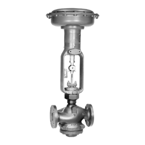
Type ACE97
2
To avoid such injury or damage,
provide pressurerelieving or pressure-
limiting devices (as required by
the appropriate code, regulation or
standard) to prevent service conditions
from exceeding limits.
Additionally, physical damage to the
valve could result in personal injury and
property damage due to escaping fluid.
To avoid such injury and damage, install
the valve in a safe location.
Clean out all pipelines before installation of the valve
and check to be sure the valve has not been damaged
or has collected foreign material during shipping. For
NPT bodies, apply pipe compound to the external pipe
threads. For flanged bodies, use suitable line gaskets
and approved piping and bolting practices.
The valve must be mounted so the actuator case is
horizontal. The valve should be mounted above the
tank. For connections are required: a) blanketing
gas supply to the valve, b) vapor recovery/process
connection (vent), c) system tank connection and d)
sensing line to the tank.
Overpressure Protection
The recommended pressure limitations are stamped
on the valve nameplate. Some type of overpressure
protection is needed if the actual inlet pressure
exceeds the maximum operating outlet pressure
rating. Overpressure protection should also be
provided if the valve inlet pressure is greater than the
safe working pressure of the downstream equipment.
Valve operation below the maximum pressure
limitations does not preclude the possibility of
damage from external sources or debris in the line.
The valve should be inspected for damage after any
overpressure condition.
Startup
Slowly open the tank and sensing line shutoff valves
(between the Type ACE97 and the tank). A tank vapor
space pressure gauge should be installed and visible.
Slowly open the inlet shutoff valve (to the pad valve)
and leave it fully open.
Adjustment
The setpoint of this unit if factory set. If an adjustment
is to be made, it should be made in small increments
while the unit is controlling tank pressure. It is difficult
to make field adjustments due to the slow changes in
tank pressure.
Taking Out of Service (Shutdown)
!
WARNING
To avoid personal injury resulting from
sudden release of pressure, isolate
the valve from all pressure before
attempting disassembly.
Parts List
Key Description
16* O-ring
17 Bonnet (pad valve)
18 Body (pad valve)
19* O-ring (DN 25 and 50 / NPS 1 and 2pad valves only)
20 Round-Head Machine Screw (DN 25 and 50 / NPS 1 and 2
pad valves only)
21 Lock Washer (DN 25 and 50 / NPS 1 and 2 pad valves only)
22 Plug (DN 25 and 50 / NPS 1 and 2 pad valves)
23* O-ring (DN 25 and 50 / NPS 1 and 2 pad valves)
24* O-ring (DN 25 and 50 / NPS 1 and 2 pad valves)
25 Piston (main valve, DN 25 and 50 / NPS 1 and 2 pad valves)
26 Spring (Pad Main Valve)
27 Gasket (bonnet, pad valve)
28 Lock Washer
29 Hex-Head Machine Screw
31 Hex Nut
34 Spring Shim (DN 25 / NPS 1 pad valve)
35 Lower Cage (DN 25 and 50 / NPS 1 and 2 pad valves)
36 Spring (pad pilot valve)
37 Piston (pad pilot valve)
38* Diaphragm (pad and depad pilot valves)
39* O-ring
40 Upper Cage (DN 25 and 50 / NPS 1 and 2 pad valves)
41* O-ring
42 Poppet (pad pilot valve)
46 Seal Bushing
49 Spring Guide (pad valve)
50 Hex-Head Cap Screw
51 Lock Washer
52 Cage (DN 15 / NPS 1/2 pad valve)
75 Stem
76* O-ring
77 Cage (depad main valve)
78 Hex-Head Machine Screw
79 Lock Washer
80 Seal Retainer
81* Stem Seal
82* O-ring
83 Steal Retaining Plate
84 Spring (depad main valve)
85 Spring Guide (depad main valve)
86 Retaining Ring (1 and 2 NPT depad main valves)
87 Bonnet
88* O-ring (1 NPT depad main valve)
89 Retaining Ring
90 Cap (1 NPT depad main valve)
91 Body (depad main valve)
