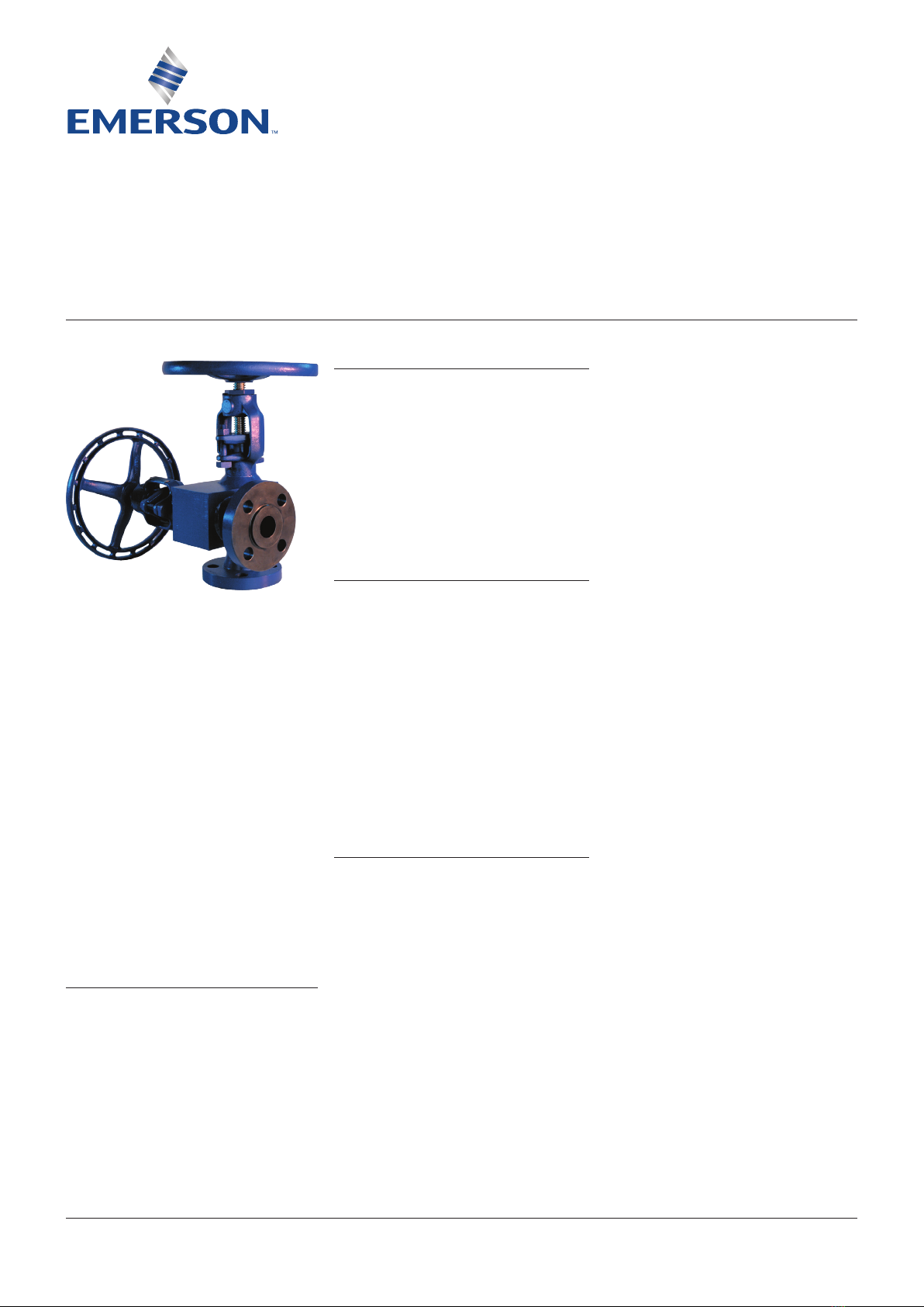
Emerson Yarway User manual
Other Emerson Control Unit manuals

Emerson
Emerson Fisher 98LD User manual

Emerson
Emerson Liebert OpenComms SL-19534 User manual

Emerson
Emerson CV4-7 Series User manual

Emerson
Emerson NEOTECHA SNB Series User manual

Emerson
Emerson RSTi-OM User manual

Emerson
Emerson Fisher VS100 Series User manual

Emerson
Emerson AVENTICS User guide

Emerson
Emerson CROSBY Guide

Emerson
Emerson Neotecha Sapro User manual

Emerson
Emerson Fisher OSE User manual

Emerson
Emerson VS-FL Series User manual

Emerson
Emerson EXD-U02 User manual

Emerson
Emerson PACSystems VersaMax IC200CMM020 User manual

Emerson
Emerson KTM RICHARDS FIGURE R382 User manual

Emerson
Emerson KTM VIRGO E Series Manual

Emerson
Emerson EIM 2000 Series User manual

Emerson
Emerson Fisher EZ easy-e User manual

Emerson
Emerson Fisherr D2 FloPro User manual

Emerson
Emerson ANDERSON GREENWOOD 96A Series Manual

Emerson
Emerson FISHER NotchFlo DST User manual


Popular Control Unit manuals by other brands

Festo
Festo Compact Performance CP-FB6-E Brief description

Elo TouchSystems
Elo TouchSystems DMS-SA19P-EXTME Quick installation guide

JS Automation
JS Automation MPC3034A user manual

JAUDT
JAUDT SW GII 6406 Series Translation of the original operating instructions

Spektrum
Spektrum Air Module System manual

BOC Edwards
BOC Edwards Q Series instruction manual

KHADAS
KHADAS BT Magic quick start

Etherma
Etherma eNEXHO-IL Assembly and operating instructions

PMFoundations
PMFoundations Attenuverter Assembly guide

GEA
GEA VARIVENT Operating instruction

Walther Systemtechnik
Walther Systemtechnik VMS-05 Assembly instructions

Altronix
Altronix LINQ8PD Installation and programming manual