F Series
3
Valves with brass materials must not be
used on anhydrous ammonia service.
Installation
CAUTION
Do not install the valve in any piping
which tends to restrict the valve inlet.
This may prevent the excess ow valve
from closing.
Flow through the excess ow valve must
be in the same direction as the ow
arrow stamped on the valve.
1. A rule of thumb for sizing excess ow valves is to
choose a valve with a closing ow 1.5 times the
maximum operating ow. For surge conditions,
2 times maximum ow may be required.
However, the excess ow valve’s closing ow rate
must be less than the capacity of the LP-Gas
or NH3 system in which the valve is being used.
The ow rating of the piping, ttings, pump, valves,
and hose on both the inlet and outlet of the excess
ow valve must be greater than the ow rating of
the excess ow valve. If branching, piping length,
additional valves, reduction in pipe size, elbows, or
other necessary components in the piping system
create restrictions which reduce the ow rating to
less than that of the excess ow valve rating, the
valve will not give excess ow protection, and
additional excess ow valves must be installed at
these points.
2. Brass valves are not suitable for NH3applications.
3. Manually operate the excess ow valve’s poppet
before installation to assure parts were not damaged
in shipment or blocked with dirt or foreign material.
4. Use pipe dope on the male threads of the
valve or the pipeline. PTFE tape or PTFE pipe
dope compound is recommended for the male
threads of the larger valves such as the NPS 2
and 3 (DN 50 and 80) sizes.
5. After the excess ow valve is installed, the
system should be tested for excess ow valve
operation by simulating a break downstream
in the system at the furthermost point being
protected. To test the unit, pressure the
system and then open a shutoff vave quickly
at the farthest point in the piping that the excess
ow valve is intended to protect. There should
be a sudden decrease in ow, indicating that
the valve has closed and is working properly.
reductions in pipe diameter, or a number of other
in-line valves or ttings), low operating pressure as
a result of ambient temperature, or a partially closed
valve downstream from the excess ow valve. Due
to the variety of conditions, in the case of a hose
separation, that can restrict the rate of ow below the
level necessary to activate the excess ow valves, the
F Series excess ow valves cannot be used to satisfy
the passive shutdown equipment requirement under/
in 49 CFR§173.315(n)(2). Also, a Design Certifying
Engineer cannot include the F Series excess ow
valve as a component of the discharge system in any
DCE certication under 49 CFR§173.315(n)(2).
!
EXPLOSION HAZARD
DO NOT USE the F Series excess
ow valves to satisfy the passive
shutdown equipment requirement in
49 CFR§173.315(n)(2). DO NOT
include the F Series excess ow valves in
a DCE certication under
49 CFR§173.315(n)(2). The cargo tank
manufacturer must install some other
equipment that satises the requirement
for passive shutdown capability under
49 CFR§173.315(n)(2).
Failure to follow this warning could result
in serious personal injury or property
damage from a re or explosion in the
event of an unintentional release of
product during an unloading operation.
Description
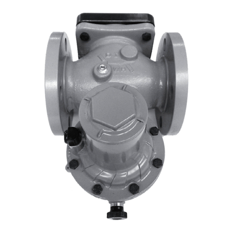
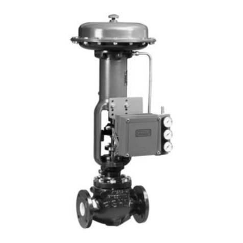
Excess ow check valves close when the ow rate of
vapor or liquid exceeds the valve’s rated ow capacity.
They are used to protect cylinder, tank, and piping
systems. The valves are available in a variety of sizes
and body congurations.
When ow exceeds the valve’s setting, the valve closes
and remains closed until the system equalizes. A built-
in equalizing passage automatically opens the valve
once pressures on both sides of the poppet are equal.
Specications
CAUTION
If the valve is to be used in service other
than LP-Gas or anhydrous ammonia,
contact the factory to determine if the
valve materials are suitable for the
particular service.
