manuals.online logo
Brands
  1. Home
  2. •
  3. Brands
  4. •
  5. Emerson
  6. •
  7. Control Unit
  8. •
  9. Emerson FISHER F180 Series User manual

Emerson FISHER F180 Series User manual

F180 Series
D450016T012
Instruction Manual
MCK-1094
February 2008
R
www.emersonprocess.com/regulators/lp
F180 Series Excess Flow Valves for
Compressed Air Service
!
WARNING
Failure to follow these instructions or to
properly install and maintain this
equipment could result in property
damage and personal injury or death.
Fisher®equipment must be installed,
operated, and maintained in accordance
with federal, state, and local codes and
Fisher instructions.
Only personnel trained in the proper
procedures, codes, standards, and
regulations of the applicable industries
should install and service this equipment.
!
WARNING
A break or leak downstream of an
excess ow valve that does not allow a
ow equal to the valve ow rating will
not actuate the excess ow valve and
could result in property damage or
personal injury from a whipping hose or
high volume discharge of air. For this
reason the operator must be familiar
with the system shutoff valves and close
the system if an emergency occurs.
Introduction
Scope of Manual
This instruction manual covers installation and
maintenance for F180 Series excess ow valves used
on compressed air service.
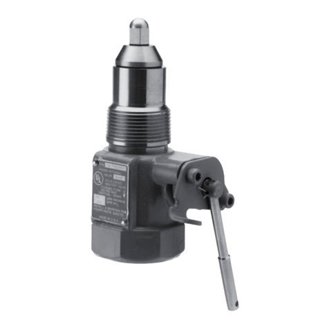
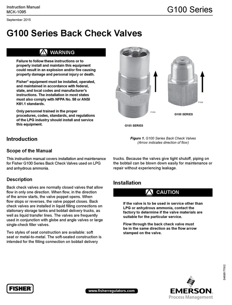
Figure 1. F180 Series Excess Flow Valves
TYPE F186
TYPE F187
TYPE F188
F180 Series
2
Specications
Description
Excess ow check valves close when the ow rate
of air exceeds the valve’s rated ow capacity. They
are used to protect against the dangers of a whipping
hose. The valves are available in a variety of sizes
and body congurations.
When ow exceeds the valve’s setting, the valve
closes and remains closed until the system equalizes.
A built-in equalizing passage automatically opens the
valve once pressures on both sides of the poppet
are equal.
Specications
CAUTION
If the valve is to be used in service other
than compressed air, contact the factory
to determine if the valve materials are
suitable for the particular service.
Valves with brass materials must
not be used on anhydrous ammonia
(NH3) service.
Installation
CAUTION
Do not install the valve in any hose or
piping which tends to restrict the valve
inlet. This may prevent the excess ow
valve from closing.
Flow through the excess ow valve must
be in the same direction as the ow
arrow stamped on the valve.
1. A rule of thumb for sizing excess ow valves is
to choose a valve with a closing ow 1.5 times the
maximum operating ow. For surge conditions,
2 times maximum ow may be required.
However, the excess ow valve’s closing ow rate
must be less than the capacity of the compressed
air system in which the valve is being used. The ow
rating of the piping, ttings, pump, valves, and hose
on both the inlet and outlet of the excess ow valve
must be greater than the ow rating of the excess ow
valve. If branching, piping length, additional valves,
reduction in pipe size, elbows, or other necessary
TYPE
INLET
CONNECTION,
INCHES
OUTLET
CONNECTION,
INCHES
MATERIAL
CLOSING
FLOW,
AIR SCFM
(meters3/min) AT
100 PSIG
(6,9 bar) INLET
PRESSURE
CLOSING FLOW
DIFFERENTIAL
PRESSURE,
PSIG (bar)
BODY LENGTH,
INCHES (cm)
WRENCH HEX,
INCHES (cm)
F186-06-1 3/4 MNPT 3/4 FNPT Brass 171 (4,8) 11 (0,76) 1.85 (4,7) 1.31 (3,3)
F187-08-1 1 FNPT 1 FNPT Brass 189 (5,4) 3.3 (0,23) 3.47 (8,8) 1.75 (4,4)
F187-12-1 1-1/2 FNPT 1-1/2 FNPT Brass 416 (11,8) 4.7 (0,32) 4(10,2) 2.25 (5,7)
F187-16-1 2 FNPT 2 FNPT Brass 879 (24,9) 4.2 (0,29) 4.56 (11,6) 3(7,6)
F188-24-1 3 FNPT 3 MNPT x
2 FNPT Steel 1729 (49,0) 7.1 (0,49) 6.22 (15,8) 3.75 (9,5)
Maximum Operating Pressure: 250 psig (17,2 bar)
Maximum Differential Pressure: 15 psig (1,03 bar)
Closing Flow Tolerance: +10% to -20% of rated ow
F180 Series
3
components in the piping system create restrictions
which reduce the ow rating to less than that of the
excess ow valve rating, the valve will not give excess
ow protection, and additional excess ow valves must
be installed at these points.
2. Brass valves are not suitable for anhydrous
ammonia (NH3) applications.
3. Manually operate the excess ow valve’s poppet
before installation to assure parts were not
damaged in shipment or blocked with dirt or
foreign material.
4. Use pipe dope on the male threads of the valve or
the pipeline. Polytetrauoroethylene (PTFE) tape
or PTFE pipe dope compound is recommended for
the male threads of the larger valves such as the
2 and 3-inch sizes.
5. After the excess ow valve is installed, the system
should be tested for excess ow valve operation
by simulating a break downstream in the system
at the furthermost point being protected. To test
the unit, pressure the system and then open a
shutoff valve quickly at the farthest point in the
piping that the excess ow valve is intended to
protect. There should be a sudden decrease in
ow, indicating that the valve has closed and is
working properly. Because of the bleed that
permits the valve to equalize itself, a small amount
of leakage will continue after the excess ow
check closes.
6. To reopen a closed excess ow valve, close a
shutoff valve on either the upstream or
downstream piping. When pressure is equal on
both sides of the valve, it will “click” open and ow
can be resumed by opening the shutoff valve.
!
WARNING
Trained personnel should test the
excess ow valve in a safe location.
Excess ow closure should be checked
annually or on a regularly scheduled
basis to insure that the valve is
still functional.
Maintenance
Excess ow valves are non-repairable. Replace
non-functioning valves.
Troubleshooting
If the excess ow valve fails to close – check
the following:
1. Flow direction is the same direction as
arrow stamped on the valve.
2. Shut off valves on the inlet and outlet of the
piping are fully open.
3. Restrictions on the inlet or outlet of the excess
ow valve are restricting ow into or out of
the valve.
4. Flow capacity at point of test is not great enough
to close the excess ow valve.
5. Pipe scale, welding slag, or other debris is holding
the valve open.
Premature closing or valve chattering – check
the following:
1. Surge conditions – Increase ow slowly to
prevent surge. A larger excess closing ow may
be required.
2. Chattering – Normal ow conditions may be too
near to the closing ow rate, or ow direction is
wrong or back owing is occuring.
3. Restriction on inlet of valve.
!
WARNING
Back owing or owing too near to the
excess ow valve closing rate may cause
chattering which may result in excessive
wear on parts and valve failure.
F180 Series
Fisher and Fisher Regulators are marks owned by Fisher Controls International, LLC. The Emerson logo is a trademark and service mark of Emerson Electric Co. All other marks are the
property of their respective owners.
The contents of this publication are presented for informational purposes only, and while every effort has been made to ensure their accuracy, they are not to be construed as warranties or guarantees, expressed
or implied, regarding the products or services described herein or their use or applicability. We reserve the right to modify or improve the designs or specications of such products at any time
without notice.
Fisher does not assume responsibility for the selection, use or maintenance of any product. Responsibility for proper selection, use and maintenance of any Fisher product remains solely with
the purchaser.
Emerson Process Management
Fisher Controls International, LLC.
P.O. Box 8004
McKinney, Texas 75070, USA
Telephone: 1 (800) 558-5853
Telephone: 1 (972) 548-3574
©Fisher Controls International, LLC., 2002, 2008; All Rights Reserved www.emersonprocess.com/regulators/lp

This manual suits for next models

3

Other Emerson Control Unit manuals

Emerson Daniel 700 Series Quick start guide

Emerson

Emerson Daniel 700 Series Quick start guide

Emerson Control Techniques FM-4 User manual

Emerson

Emerson Control Techniques FM-4 User manual

Emerson Fisherr D2 FloPro User manual

Emerson

Emerson Fisherr D2 FloPro User manual

Emerson TESCOM 64-2600 Series User manual

Emerson

Emerson TESCOM 64-2600 Series User manual

Emerson 289 Series User manual

Emerson

Emerson 289 Series User manual

Emerson Bettis Q series User manual

Emerson

Emerson Bettis Q series User manual

Emerson Fisher 63EGLP Series User manual

Emerson

Emerson Fisher 63EGLP Series User manual

Emerson NEOTECHA NEOSEAL User manual

Emerson

Emerson NEOTECHA NEOSEAL User manual

Emerson 1805 Series User manual

Emerson

Emerson 1805 Series User manual

Emerson Fisher POSI-SEAL A31A User manual

Emerson

Emerson Fisher POSI-SEAL A31A User manual

Emerson Anderson Greenwood Quick start guide

Emerson

Emerson Anderson Greenwood Quick start guide

Emerson Liebert OpenComms SL-19534 User manual

Emerson

Emerson Liebert OpenComms SL-19534 User manual

Emerson Heated Flame Ionization Detector Module Model NGA 2000... User manual

Emerson

Emerson Heated Flame Ionization Detector Module Model NGA 2000... User manual

Emerson Fisher MR98LD User manual

Emerson

Emerson Fisher MR98LD User manual

Emerson Topworx D Series Instruction manual

Emerson

Emerson Topworx D Series Instruction manual

Emerson Fisher Vee-Ball V200 User manual

Emerson

Emerson Fisher Vee-Ball V200 User manual

Emerson Fisher GX User manual

Emerson

Emerson Fisher GX User manual

Emerson IC200UEM001 User manual

Emerson

Emerson IC200UEM001 User manual

Emerson Fisher 8540 User manual

Emerson

Emerson Fisher 8540 User manual

Emerson Alco Controls M36 Series User manual

Emerson

Emerson Alco Controls M36 Series User manual

Emerson Spence K3 User manual

Emerson

Emerson Spence K3 User manual

Emerson Fisher CCV-N User manual

Emerson

Emerson Fisher CCV-N User manual

Emerson EX4-6-...FLR Series User manual

Emerson

Emerson EX4-6-...FLR Series User manual

Emerson White Rodgers 36H Series User manual

Emerson

Emerson White Rodgers 36H Series User manual

Popular Control Unit manuals by other brands

Viessmann VITOCONNECT OPTO2 operating instructions

Viessmann

Viessmann VITOCONNECT OPTO2 operating instructions

Applied Motion Products Mechanical Outline 3540 user manual

Applied Motion Products

Applied Motion Products Mechanical Outline 3540 user manual

NI PXI-6682H user manual

NI

NI PXI-6682H user manual

PICOLAS LDP-CWL 06-20 user manual

PICOLAS

PICOLAS LDP-CWL 06-20 user manual

System Sensor M501MAP Installation and maintenance instructions

System Sensor

System Sensor M501MAP Installation and maintenance instructions

Texas Instruments DLP NIRscan EVM user guide

Texas Instruments

Texas Instruments DLP NIRscan EVM user guide

Danfoss RLV instructions

Danfoss

Danfoss RLV instructions

CALEFFI 513 Series manual

CALEFFI

CALEFFI 513 Series manual

Shure DIS-CCU quick start guide

Shure

Shure DIS-CCU quick start guide

Spirax Sarco DP27 Installation and maintenance instructions

Spirax Sarco

Spirax Sarco DP27 Installation and maintenance instructions

Emco A1100 Series Assembly and installation instructions

Emco

Emco A1100 Series Assembly and installation instructions

LG Innotek WL1NB6 user manual

LG Innotek

LG Innotek WL1NB6 user manual

Ingersoll-Rand BAYLOAM335 installation instructions

Ingersoll-Rand

Ingersoll-Rand BAYLOAM335 installation instructions

Siemens SIMATIC FM 453 Getting started

Siemens

Siemens SIMATIC FM 453 Getting started

Burkert 6013 operating instructions

Burkert

Burkert 6013 operating instructions

Ring Engineering LM-4S-G user manual

Ring Engineering

Ring Engineering LM-4S-G user manual

AGA PROSAVER operating instructions

AGA

AGA PROSAVER operating instructions

Niles SCW-2 Installation & operation guide

Niles

Niles SCW-2 Installation & operation guide

manuals.online logo
manuals.online logoBrands
  • About & Mission
  • Contact us
  • Privacy Policy
  • Terms and Conditions

Copyright 2025 Manuals.Online. All Rights Reserved.