BEINAT GS920 User manual

Belonging to
GS920 - V. 3
230 VAC
12 VDC
12 VDC
230 VAC
Gas Detector with Seismic Device
To protect your family
The GS920 is a high-tech technical device thanks to the innovation of "Seismic detection" and
the ability to select the "Intrinsic Safety control".
To built this complete, highly flexible control system, we relied on a microprocessor which,
combined with the Catalytic sensor technology, detects the explosive gases such as METHANE
and LPG with an intervention threshold set at 10% of the L.E.L.
Through the built-in relay, the GS920 can active solenoid valves, sirens and any other alarm
signaling device.
Through a micro switch it is possible to choose between an impulse mode of the relay to connect
solenoid valves with manual reset and continuous mode, to operate normally closed solenoid
valves in class "A", and sirens.
With another microswitch, it is possible to enable or disable the "Positive Safety".
The power supply unit allows you to enable a manual reset solenoid valve with a 12 VDC coil,
without the need of a buffer battery.
With the "Seismic Control", the solenoid valve is closed if necessary, effectively stopping the
gas at the origin. This control is vital in seismic areas
The technical scheme is completed by the special "Control Circuit of the degree of efficiency" of
the catalytic sensor, which promptly signals any possible fault
These technical features make the detector ideal for civil environment safety according to
EUROPEAN STANDARD.
Important: Assembly / maintenance of the appliance must be carried out by qualified personnel
and in accordance with applicable laws and regulations.
The manufacturer assumes no responsibility for the use of products that have to comply with
particular environmental and / or installation standards.
Important note
Before connecting the equipment, it is recommended that you read the instruction manual
carefully and keep it for future reference. It is also recommended to perform the electrical
connections correctly as per enclosed drawings, observing the instructions and the Standards.
N.B. Refer to the documentation in all cases where the symbol is on the side
Channel: Beinat gas solutions
Electric connections also available on
CONFORMITY
Installationand
userguide
EN 50194
EN 50270
CEI 216-3
EN 61010-1
Installation EN 60079-29-2

Page 2
CHECK the integrity of the detector after having removed it from the box.
Check that the data written on the box correspond to the type of gas used.
When doing the electrical connections, follow the drawing closely.
Any use of the detector for purposes other than the intended one is considered improper, and as a result of
which BEINAT S.r.l. therefore disclaims any responsibility for possible damages caused to people, animals
or objects.
TERMS and EXPECTATIONS: The installation of the detector, its ordinary and extraordinary maintenance,
and its out of service removal at the end of the functional life guaranteed by the manufacturer, must be carried
out by authorized and/or specialized personnel.
To use your gas detector for a long time and with satisfaction, use it with the following precautions in mind.
Do not wet it.
The detector is not waterproof if immersed in water or exposed to high humidity can be seriously damaged.
Do not drop it.
Heavy knocks or falls during transportation or installation can damage the appliance.
Avoid abrupt temperature fluctuations.
Sudden temperature variations can cause condensation and the probe could work poorly.
Cleaning
Never clean the device with chemical products. If necessary, wash with a moist cloth.
Absolutely avoid using any cloth dipped in thinners, alcohol and chemical detergents.
MAINTENANCE
The user periodically (every 6 months) must perform a check of the operation of the control unit by spraying
a suitable test gas at the base of the probes connected until the alarm condition is reached.
a) At least once a year make a more accurate check by a specialist technician.
b) Disapol of the detector must be carried out by qualified personnel.
Functional Features Of Gas Sensors
The installation of the GS920 detector, its ordinary and extraordinary maintenance, and its out of service
removal at
the end of the functional life guaranteed by the manufacturer, must be carried out by authorized and/or
specialized personnel.
The CATALYTIC technology sensor duration is guaranteed for 6 years (in clean air).
The detector’s functioning temperature ranges from -10°C to + 40°C.
WARNING!
The CATALYTIC probe does not tolerate a gas detection exceeding 100% of L.E.L., with consequent natural
death of the sensor.
Each immediate puff of gas that exceeds 100% of L.E.L. takes away months of life from the sensor.
The detector must be tested by simulating the presence of gas by issuing it from a pre-calibrated testing
aerosol.
A common cigarette lighter near the sensor does not guarantee excellent functioning.
Mains power .................................................................................... 230/240 VAC 50/60 Hz +/- 10%
Battery power (optional).......................................................................................... 12 V. dc ± 10%
Current consumption ....................................................................................................... 3.6W @ 230V
Range of relay contact switching ................................................................................. 10A 250V resistive
Battery charger ...................................................................................controlled by the microprocessor
Type of insulation ............................................................................................................... Classe II
Type of gas detected: .................................................................. Methane with model for Natural Gas
LPG with model for LPG
Explosive gas sensor .......................................................................................................... Catalytic
Explosive gas detector alarm threshold ........................................................................... At 10% of L.E.L.
Sensor’s faults detected by Fault Circuit ............................................. Interruption, short circuit, or wear
Detection capsule end-of-life warning ................................................................................. After 6 years
Positive safety control ........................................................................................................... Built in
Timed or continuous functioning solenoid valve selection ...................................................... Using a switch
Earthquake-proof sensor ...................................................................................... Three-axis accelerometer
Trigger sensitivity ............................................................................... 6th degree on the Mercalli scale
Audible and visual signal alarm by ........................................................................... LED diode and buzzer
Test phase duration ................................................................................................................ 60 seconds
Functioning temperature ................................................................................................. -10°C to +40°C
Functioning humidity ............................................................................................ 0÷90% RH non condensed
External degree of protection ......................................................................................................... IP42
Mounting ............................................................................... External wall mount, or embedded box 503
Body material .......................................................................................................... ABS self-extinguishing
Dimensions ........................................................................................................................... 115x150x52
Electromagnetic Compatibility CE Reference legislation .......................................................... EN 50270
Precautions
Technical features

Page 3
1) Green LED on. When flashes, the GS920 performs a test of the sensor’s efficiencystatus, and gets it to
the functioning temperature. This phase lasts 60 seconds and stop flashing so the GS920 is ready to
detect.“During the first 10 days from the last reset (or power fault) the green LED will turn off at regular intervals
to signal the seismic auto-learning phase.
2) Yellow LED, FAULT and functional life wear indication“If this LED turns on, it means that the gas detection
catalytic sensor is not working efficiently and must be replaced by an“authorized technician.
The blinking of this LED indicates that the GS920 has detected a vibration.
3) Red ALARM signaling LED. This LED lights up when the amount of gas dispersed in the environment
exceeds the danger threshold, 10% of the L.E.L.
4) Microswitches group:
Switch 1: switch ON - Positive Safety Function; the relay will be energized at the end of the latency time
and will switch at each alarm.
Switch OFF - Normal Function, the relay switches at each alarm.
Switch 2: switch ON, the relay will operate in pulses, each pulse has a duration of about 30 seconds.“Switch
OFF, the relay will work continuously, until the gas threshold falls below the danger threshold.
5) Catalytic sensor for explosive Methane or LPG gas detection.
6) TEST button. This button is used to simulate a gas leak after installation.
7) RESET button. This button is used to stop the alarm when it is triggered by a SEISMIC event
8) Identification label, serial number and manufacture date are located under the ABS dome
9) TEST POINT for testing. It is used in the laboratory or by an authorized technician.
10) Expiry date label of the gas detector.
This label must be applied by the technician during installation, bearing in mind that the detector must
be overhauled after 5 years
GS920
Methane
10 Replacement
2025
S.N. 12472
Year 2020
Year 2017
1
23
5
6
8
4
1 2
ON
7
9
1 2 3 4 5 6 7 8 Positive safety on
Pulse operation relay
Continuous operation relay
Positive safety off
Componentsandcommands
The installation of the detector does not exempt from ... ... The compliance with all regulations concerning the characteristics, installation and use
of gas appliances. The ventilation of the spaces and the elimination of combustion products are described in the UNI norms according to ART. 3 LAW 1083
/ 71 and relevant legal provisions.

Page 4
The solenoid valve drawn is an NC. Automatic or
Manual“
To connect a NO solenoid valve. change the
connection from 8 to 6
The solenoid valve drawn is an NC. Automatic or
Manual
ATTENTION !“A solenoid valve cannot be
connected“Normally open
230 VAC power supply with N.C. Solenoid valve connection. powered at 12 VDC using a battery;
Positive safety off.
Diagrams of the Gas Detector with
GS920 Seismic System.“
ATTENTION ! The relay is voltage free
Without Positive safety With Positive safety
Power supply
230 VAC
Ph
N
1 2 3 4 5 6 7 8
Power supply
230 VAC
Ph
N
1 2 3 4 5 6 7 8
Connection of an N.C. solenoid valve 230VAC with and without Positive Safety
NC
C
NO
N
Power supply
230 VAC
Ph
++
1 2 3 4 5 6 7 8
Solenoid valve N.c. and 12V DC siren
12V battery
Max. 1.2 Ah
12 V
Power supply
230 VAC Pulse solenoid valve N.O. 12V DC
NC
C
NO
N
Ph
++
1 2 3 4 5 6 7 8
12V battery“
OPTI ONAL
12 V
WARNING
Before connecting to the mains power, ensure the voltage is correct.
Carefully follow the instructions and the connections according to Regulations in force.
An automatic disconnetting switch (appropriately identified as the detector sectioning device) must
be incorporated in the electrical system, suitably located and easily accessible.
Electrical connections

34 mm
50 mm
++++
Ph
N
1 2 3 4 5 6 7 81 2 3 4 5 6 7 8
Power supply
230 V AC
NC
C
NO
N
Power supply
230 VAC
Ph
+
1 2 3 4 5 6 7 8
230 VAC siren
Solenoid valve N.O. 12V DC
+
Connection with a normally open 12V DC impulse valve
ATTENTION !!
When making the connection, remember
to move the micro Switch 2 to ON. (see
page 4)
The solenoid valve in the drawing is a Normally Open with Manual Reset powered at 230 VAC.
Connection of 2 or more Gas Detectors in Parallel Without Positive Safety
Page 5
Embedded box 503
70 mm
105 mm
5 mm
150 mm
84 mm
115mm
Electrical connections

The GS920 is suitable for mounting externally on a wall
At the time of installation it is good to use the normal diligence that an electronic equipment requires, Therefore:
- Install the detector away from excessive heat sources.
- Prevent liquids from coming into contact with the detector, remembering that the external structure has an
IP42 degree of protection.
Must not be installed:
1) behind barriers that hinder the prompt gas detection.
2) near aspirators or fans.
3) do not install the detectors near: washcloths, air vents, heating or air conditioning devices, windows or
ventilation devices.
4) must not be installed in closed spaces such as: behind a curtain or inside a wardrobe.
5) in environments where the temperature is between -10 ° C. and + 40 ° C.
The detector is designed to detect different types of gas and according to these it must be positioned at different
heights.
These heights are:
- 30 cm. from the lowest point of the floor to detect heavy gases (G.P.L. etc.)
- 30 cm. from the highest point of the ceiling to detect light gases (Methane etc.)
- Install the detector 1m to 4m from gas appliances
Methane gas
max. 30 cm from the ceiling
LPG gas
max. 30 cm from the floor
After switching on the power, the Green LED starts flashing for about 60 seconds, after this time, the LED stays on steadily,
now GS920 is ready to detect gas only.
After 24 hours from installation, the device begins to perform seismic auto-learning;
The detector must NOT be moved from the installation site for any reason, GS920 is recording all
movements and noises of the installation site.
The duration of the registration lasts 11 days.
N.B. Operation, gas detection after 60 seconds, seismic detection after 11 days.
Testing
Press the button next to the detector capsule to simulate a gas leak, the ALARM LED lights up and the relay changes its working
status after 5 seconds.
Once the alarm is over, the LED goes off, the buzzer stops and the connected devices are deactivated.
To complete the general test, emit gas from a pre-calibrated gas spray within 10% of L.E.L.. Testing with a common cigarette
lighter could damage the sensor.
It is advisable to perform this test at least once a year.
IMPORTANT: the detector operation test must not be carried out with the gas valve open,
1) because it is very dangerous to do this test.
2) because it is not possible to calculate how many liters of gas are released into the environment, to activate the general alarm.
Page 6
Turn on and testing
OK NO! NO! The GS920 seismic detector
It must not be installed on a
plasterboard wall.
It must only be installed on masonry
walls

Page 7
Before calling a technician, check ...
- If the appliance does not turn on.
Check that the 230 VAC voltage is present at the ends of the connection terminals.“If battery powered, 12 VDC
voltage is present, and see that the battery is charged.
- If the Fault LED lights up.
If YELLOW LED lights continuously, check that the installation date has not exceeded six years.
If YELLOW LED flashes, check that the anti-seismic sensor has not tripped.“To reset the seismic sensor, simply
press the reset button.
- If the detector goes into alarm repeatedly.
Check for gas leaks.
Check that, together with the alarm signal, the FAULT light does not turn on, in this case proceed as described
in the previous paragraph.
- If the detector goes into alarm and does not close the connected equipment.
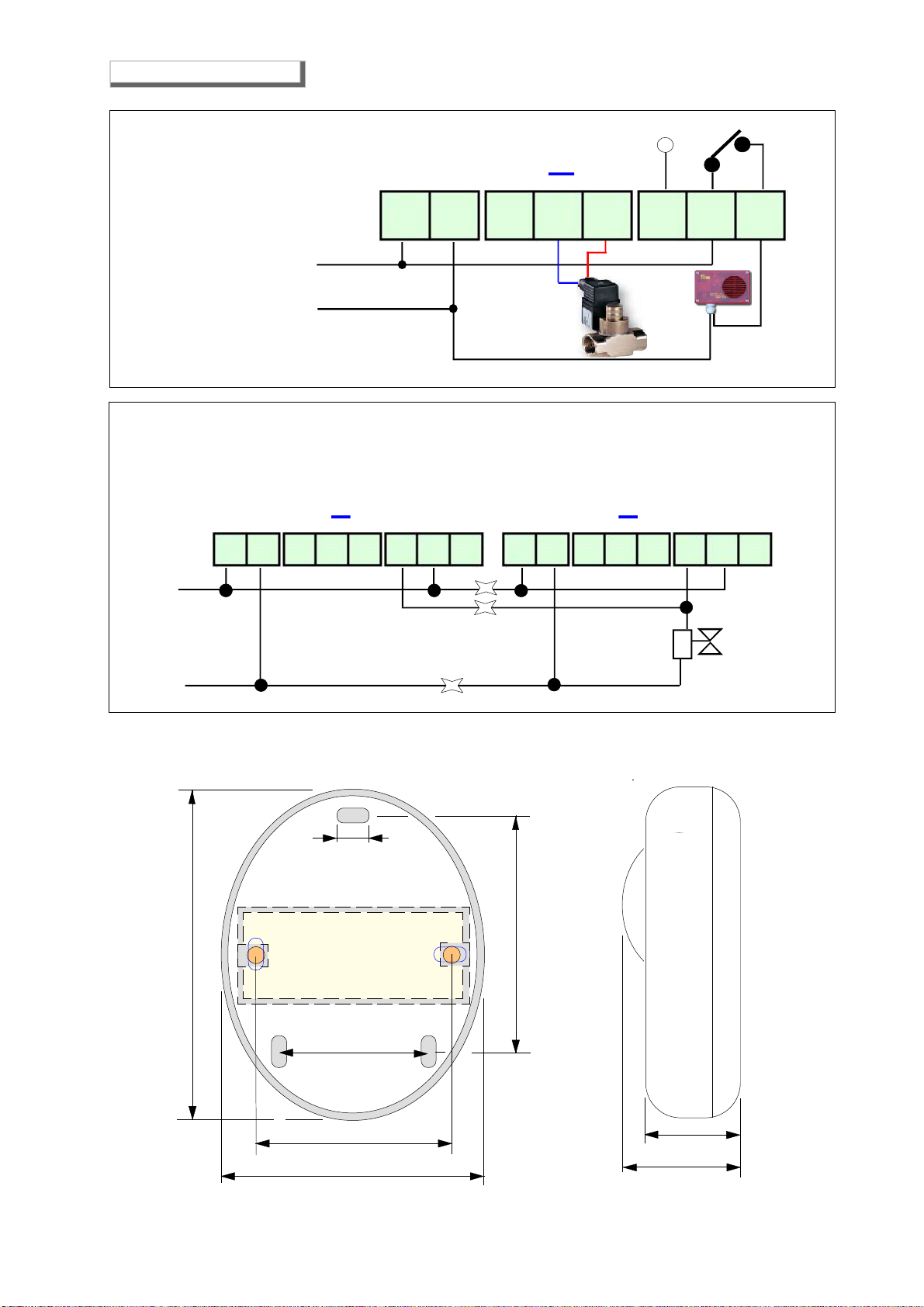
Check that the connections are correct, and that the jumper that brings voltage to the relay common has been
made, all relays are voltage free. Check the connection drawing
- If a 12 VDC solenoid valve is connected to the detector and it does not work well
Check that there are no drops in the power supply voltage.
It's cannot be directly connected to the GS920 detector 12 VDC solenoid valves or sirens with an absorption
greater than 300mA.
A battery must be used to connect a solenoid valve with higher absorption.“A 12 VDC impulse operated manual
reset solenoid valve can be directly connected to the detector.
Do not tamper with the detector.
In order not to cause the device to unbalance, and electric shocks.
MMdegree Accel(cm/s2)
1 1 Not perceived, except by a few people in particularly favorable circumstances.
2 2 Perceived by people resting on the upper floors of houses or in favorable.
3 3 Perceived in homes. Swinging of hanging objects. Vibration as when passing light trucks.
Estimated duration. Sometimes not recognized as an earthquake.
4 15-20 Swinging of hanging objects. Vibrations such as when heavy trucks pass or jolts such as a heavy ball hitting walls.
Oscillation of stationary vehicles. Movements of dishes, doors and windows.
Clink of glasses. Vibrations of crockery. In its upper stage, the creaking of wooden walls and structures.
5 30-40 Resentful to the outside; management estimate. Wake up of sleeping people. Movement of the surface of liquids,
spillage of some from containers. Moving or overturning of small unstable objects. Swing of doors that open and close.
Movement of window shutters and cadres. Stopping, starting, changing the pitch of grandfather clocks.
6 60-70 Heard by everyone. Fright, escape to the outside. Stagger of people on motorcycles.
Breakage of display cases, dishes, glassware.
Trinkets, books, etc. fell off the shelves. and paintings from the walls. Moving or overturning furniture.
Cracks in weak plaster and type D' masonry. Ringing of bells (churches, schools).
7 100-150 Difficult tostand upright. Resented by vehicle drivers. Flickering of hanging objects. Breakage of furniture. Damageto typeD' masonry,
including cracks. Breakage of weak chimneys locatedon the ridge of the roofs. Fall of plaster, bricks, stones, tiles, cornices (also of isolated parapets and architectural
ornaments). Some damage to the masonry type C*. Formation of waves on the water mirrors, clouding ofthe water. Small landslides and excavations in sand and
gravel deposits. Loud ringing of bells. Damage to lined irrigation channels.
8 250-300 Resentful in driving vehicles. Damage to walls type C*, partial collapses. Some damage to masonry type B*, not type A*. Fall of stucco
and some masonry walls. Rotation and fall of chimneys, industrialchimneys, monuments, towers, elevated tanks. Constructionswithtimber structures removed from
the foundationsif not bolted; wallpanels thrown out.Breakage of deteriorated palisades. Breakingtreebranches. Variations inflowortemperatureof springsand wells.
Cracks in the ground and on steep slopes.
9 500-550 General panic. Destruction of type D masonry, severe damage to type C masonry sometimes with complete collapse; serious damage
to type B masonry; general damage tofoundations; timber structures released fromfoundations if not bolted; timber structures tested.Serious damageto the tanks.
Rupture of underground pipes. Relevant crevasses in the ground. In alluvial areas expulsion of sand and mud, formation of sand craters.
10 >600 Destruction of most of the masonry and timber structures, with their foundations. Destruction of some robust wooden structures, with
their foundations. Destruction of somesturdy woodenstructures and bridges.Serious damage to dams,bridles,embankments. Large landslides. Dewatering of canals,
rivers, lakes, etc. Horizontal translation of sands and clays on beaches and flat regions. Weakly deflected rails.
11 --- Heavily deflected rails. Underground pipes completely out of service.
12 ---- Almost total destruction. Displacement of large rock masses. Deformed reference lines. Objects thrown into the air.
DETECTOR TRIGGERED
1) Put out all open flames, including smoking materials
2) Put out all free flames.
3) Close the main gas tap or the LPG cylinder.
4) Do not turn lights on or off; do not operate electrically powered appliances or devices
5) Open doors and windows to increase the ventilation of the environment.
If the alarm ceases, it is necessary to identify the cause and take action accordingly.
If the alarm continues and the cause cannot be identified or eliminated, leave the property and, from
the outside, notify the emergency services (fire fighters, distributors, etc.).
ATTENTION ! operations to be carried out in the event of an alarm
Effects of the Mercalli scale
If other problems arise, it is necessary to call a specialised and/or authorised technician and/or the
Distributor of BEINAT S.r.l. should be contacted directly.

Madein Italy
IP42
BEINAT S.r.l.
Via Fatebenefratelli 122/C 10077, S. Maurizio C/se (TO) - ITALY
Tel. 011.921.04.84 - Fax 011.921.14.77
http:// www.beinat.com
Help Desk - laboratorio@beinat.com
Detector GS920 Lo styling è della b & b design
Dealer Stamp
Purchase Date:
Registration Number :
Beinat S.r.l. following the targhet to improve its products, reserves the right to modify the technical features, aesthetic and functional any time
without prior notice..
INSURANCE. This device is insured by the SOCIETÀ REALE MUTUA for the PRODUCT'S GENERAL LIABILITY
up to a maximum of 1,500,000.00 EURO against damages caused by the device in case of failures in functioning.
WARRANTY. The warranty term is 3 years from manufacturing date, in agreement with the following
conditions. The components acknowledged as faulty will be replaced free of charge, excluding the replacement
of plastic or aluminium cases, bags, packing, batteries and technical reports.
The device must arrive free of shipment charges to BEINAT S.r.l.
Defects caused by unauthorized personnel tampering, incorrect installation and negligence resulting from
phenomena outside normal functioning shall be excluded from the warranty.
BEINAT S.r.l. is not liable for possible damage, direct or indirect, to people, animals, or things; from product
faults and from its enforced suspension of use.
DISPOSAL OF OLD ELECTRICAL & ELECTRONIC EQUIPMENT.
This symbol on the product or its packaging to indicates that this product shall not be treated as household waste. Instead, it shall be handed over to
the applicable collection point for the recycling of electrical and electronic equipment, such as for example:
- sales points, in case you buy a new and similar product
- local collection points (waste collection center, local recycling center, etc...).
By ensuring this product is disposed of correctly, you will help prevent potential negative consequence for the environment and human health, which could
otherwise be caused by inappropriate waste handing of this product. The recycling of materials will help to conserve natural resources. For more detailed
information about recycling of this product, please contact your local city office, your household waste disposal service or the shop where you purchased
the product.
Attention: in some countries of the European Union, the product is not included in the field of application of the National Law that applies the European
Directive 2002/96/EC and therefore these countries have no obligation to carry out a separate collection at the “end of life” of the product.
Other manuals for GS920
1
Table of contents
Other BEINAT Gas Detector manuals

BEINAT
BEINAT NASE25/S User manual

BEINAT
BEINAT SG850 User manual

BEINAT
BEINAT RGX100Q/Eg User manual

BEINAT
BEINAT CHCO User manual

BEINAT
BEINAT CO922 User manual

BEINAT
BEINAT GS911K User manual

BEINAT
BEINAT SG895 User manual

BEINAT
BEINAT NASE25 User manual

BEINAT
BEINAT SG800 User manual

BEINAT
BEINAT GSH900 User manual

BEINAT
BEINAT BXI32 User manual

BEINAT
BEINAT CHCO User manual

BEINAT
BEINAT RGX100 User manual

BEINAT
BEINAT RGX1002 User manual

BEINAT
BEINAT CHECKER-24 User manual

BEINAT
BEINAT GSH246 Series User manual

BEINAT
BEINAT CHCO User manual

BEINAT
BEINAT SGM595-H2CH User manual

BEINAT
BEINAT SGM595/A User manual

BEINAT
BEINAT NASE25/K Instruction manual