6
Reassembly
Before reassembling the valve, lubricate all
threads with a suitable high temperature nickel
compound. Do not use grease or
other oil based
lubricants as these may lead to dismantling
problems later. Apply a thin coating of
thecompound to the piston rings to prevent
scoring. Position the slots in the piston rings,
such that they are at 120° to each other.
If the seat has been removed, thoroughly
clean the area for seal ring (19) in both
thecontrol cylinder assy (3) and the seat (2).
Check thecondition of the threading, remove
blemishes and or damaged threading by
dressing with a small, fine file. In case of doubt,
insert the seat part first with no seal ring (19)
installed. If the insertion is flawless remove and
install seat ring (19).
The seal shall have grip in the seat groove
sufficiently for re-assembly. Never usegrease
or other substance to fix the seal ring.
Putthestem with piston-rings in the control
cylinder. Screw the seat with the seal inserted
carefully on the control cylinder, hand tighten.
Use a wrench to tighten the seat on the control
cylinder (both parts need to have metal surface
contact). Setting torque for model 59/69 is 400Nm,
model 79 is 650Nm.
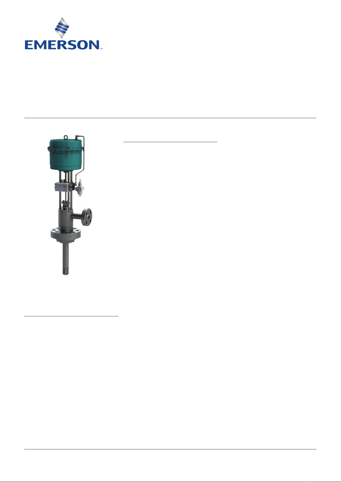
YARWAY TempLowHT DESUPERHEATER
InstallatIon and MaIntenance InstructIons
Packing set
CAUTION
Before repacking any valve, make sure all
safety precautions are taken as applicable
totheparticular valve being serviced.
1. Completely remove old packing including
any spares, washers or lantern rings,
ifany. Make sure that surfaces contacting
packing are clean. Inspect the stuffing box
and stem for straightness, wear, scratches,
pitting and other abnormalities which would
prevent establishment of a good seal around
the packing. A smooth undamaged surface
is essential for good sealing. Repair or
replace as necessary.
2. If a spacer is supplied with this packing or
if
a spacer was removed from the stuffing
box, make sure it is installed first. If one end of
thespacer is chamfered, install chamfered end
down so that it sits at bottom of stuffing box.
3. Packing is supplied as a complete set and
rings should be in same order as packaged
in the set. Install packing set in correct
order, see figure 9/10.
4. Check packing rings for proper fit.
Theyshould be push fit into stuffing box.
5. Install one ring at a time, in the proper
sequence, using a packing driver or gland
bushing. Facing must be seated individually
with a packing driver. Pre-compression
of each ring during installation is very
important for the tightness of the seal.
Donot use screwdriver or other sharp
object to seal the packing. This could
damage thepacking and/or stem. If a
packing driver is used, make sure that the
diametrical clearances between the I.D. of
the driver and O.D. of the stem and the O.D.
of thedriver and I.D. of the stuffing box do
not exceed 0.5 mm (0.020”).
6. Stagger the joints (if present) on each
successive ring 120° apart.
7. Do not over compress the packing.
Theamount of compression should be
only that which is required to the install
thecorrect number of rings into thestuffing
box. Compression of the packing in a
partially filled stuffing box, to make room for
the rest of the packing, can be accomplished
using the gland bushing and taking up on
the gland nuts.
8. When all packing has been installed in
thestuffing box and the gland bushing
and packing flange are in place, tighten
thegland
nuts evenly with a wrench to seat
and compress the complete packing set
to the stuffing box and stem. Compress
thepacking set enough to cause the packing
slightly to grip the stem (if stem movement
is performed by hand, the stem should not
move). If the stem moves with stick slip,
thepacking set is over-tightened.
9. Re-tightening of the gland nuts is necessary
within a few hours after start-up. During this
operation timeit may be necessary to adjust
the gland nuts. Check regularly.
Next operation is best performed with the
body(1) in horizontal position.
Insert spacer (11) in the stuffing box cavity.
Itwill act as a stem guide.
Install seal (4) over control cylinder assy (3)
and push the cylinder /stem combination into
thecavity of body (1). Make sure the stem
smoothly slides in the bushing (11).
Turn the body with the mounting flange upward.
Take care not to damage the stem.
Press onto the cylinder (3) by light hammering
with a deadweight hammer, or under a press
until the edge of cylinder (3) is flat with the lower
flange face. Protect the face of the cylinder
by a
piece of lead, copper or wood to avoid scratches
or dents on the facing.
Insert index pin (8) and slide gasket (5)
over thepin and match up the drillings in
thecylinder bottom.
Re-assembly the injection probe (7) by
means of the studs/nuts (15, 16). Tighten
nuts with approx. 30 Nm.Check if the flat face
between body (1) and injection probe (7) has
no clearance. If it does let rest for approx
10minutes and re-tighten.
Follow the stuffing box assembly procedure
asoutlined above.
Depending upon the built-in situation
theactuator can now be re-assembled or
later,once the TempLowHT is back in situ.
The unit is now ready for re-mounting to
thepiping system.