EMGA coffee queen 320.504 series User manual

COFFEE QUEEN
Servicemanual
*320.
320504 en ma 2012 07

320504 en ma 2012 07 2/15
Contents.
Contents 2
Introduction 3
Functionaldescription 4
Installationandstarting 5-6
Programming: Calibration 7
Faultindications 8
Important 9
Care 10
Programming:Automat–Manual 11
Exploded view, HVA 12
Explodedview,Tankcomplete 13
List of spare parts. 14
Sketch of dimensions 15
320504 en ma 2012 07 3/15
Introduction.
HVA/HVM Hot water automat
CongratulationsonchoosinganHVA/HVMhotwaterautomat.
Read through the instructions before you use the machine.
- Thismanualcontainsimportantinstructionsforcorrectandsafeusageofthehotwater
automat.
- Alwayskeepthemanualinahandyplace.
Coffee Queen AB is certified according to ISO 9001 and ISO 14001 standards
and therefore has a minimum impact on the environment.
HVA/HVM Hot water automat
- Digital display with temperature indication
- Electronictemperaturecontrol
- Manufacturedinbrightstainlesssheetmetal.
Facts mm005thgieH mm522htdiW mm014htpeD
Tank capacity 7.5 litres
Electricalconnection 230 V / 2200 W
3-phaseelectricalconnection 380 V / 8000 W
Coldwaterconnection ½”externalthread
81:yticapaC litres/hour
Capacity: 3 phase 67litres/hour
320504 en ma 2012 07 4/15
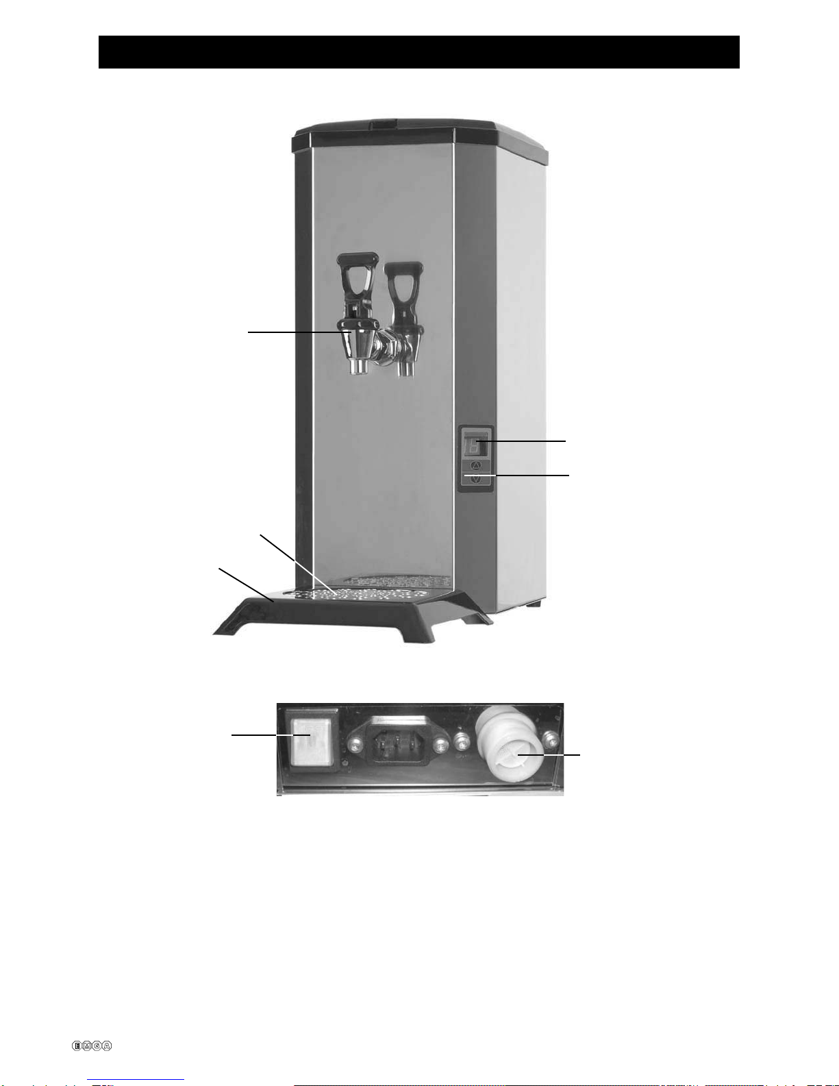
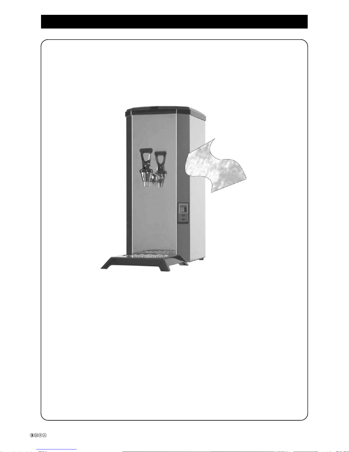
Functional description.
Hot water tap
Display
Electronic temperature
control
Drip tray insert
Functional description
Thehotwaterautomatcomprisesatankwhichholds7.5litres.
Thewater level is regulated by alevelguardthatswitchesandopens a solenoid
valve.
Thewatertemperatureisregulatedbyathermostatandanelement.
Hotwaterautomatconnectedtothewatersupply.
Drip tray
ON/OFF-
switch Connection for
filling with water

320504 en ma 2012 07 5/15
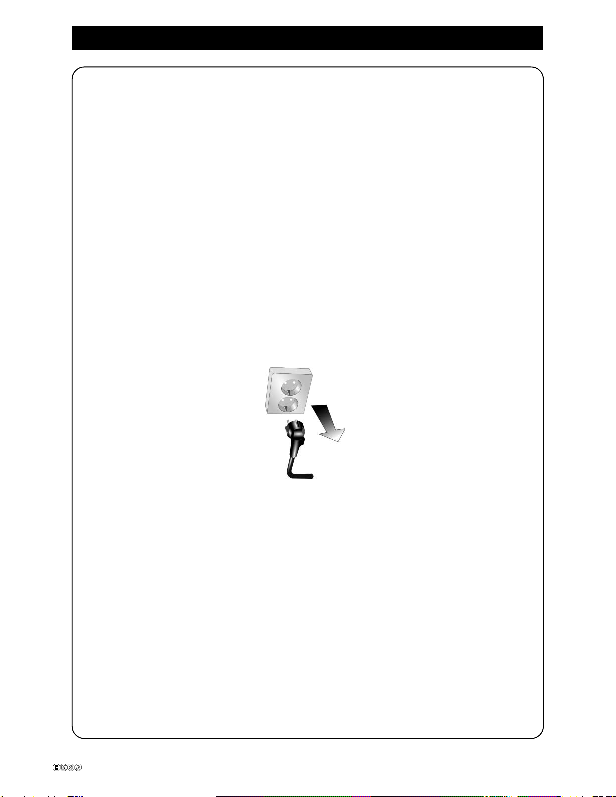
Installation and starting.
1.3. Insertthepowerpluginaseparately-earthed wall
socket. 230 V, 10 A.
1.1. Placethemachineonalevelandwatertight
surface.
1.4. Switchonusingtheswitchthatis located at the
backof the machine.
Checkthatthelightcomeson.
1.2. ConnecttotheColdwatersupplyusingthehose
provided. The most appropriate connection is to
atapthatcanbeturnedoff.
The pressure shall be 14.5 – 72.5 PSI
(1 – 5 bar) for the automat to function
properly
Refer to Programming on page 11 when filling
thewatermanually.
320504 en ma 2012 07 6/15
Installation and starting.
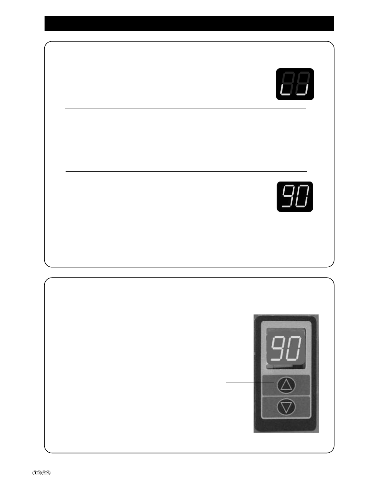
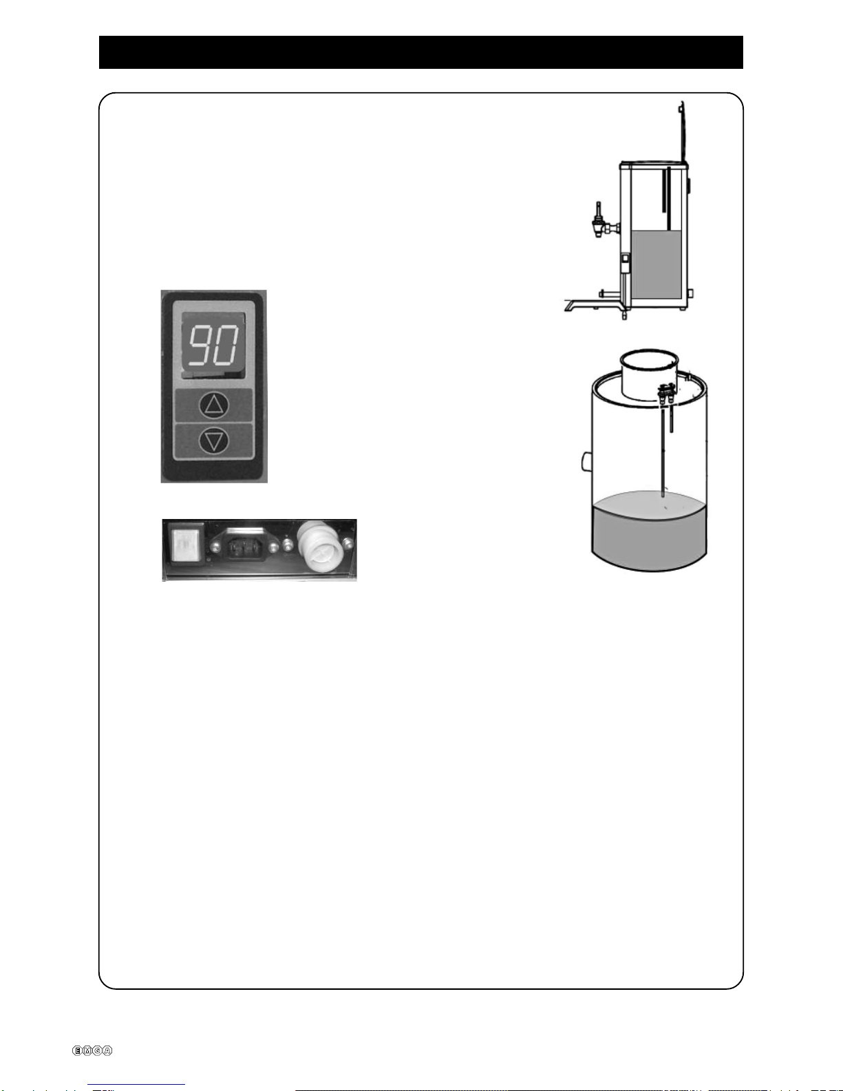
2. Setting the water temperature.
2.1. Adjust the water temperature using the membrane
switch. Max temperature 96ºC.
2.2. Increase the temperature.
2.3. Reduce the temperature.
1. The hot water automat will now start to fill and heat the water.
1.1. The display will flash when the automat fills with water
1.2. While the machineisheatingthewaterthedisplayshowstheactual
temperatureuntilthepre-selectedtemperatureisreached.
1.3. The display light stays on when the water has reached
the preset temperature of 90oC.
1.4. Thehotwaterautomatisnowreadyforuse.
Theoperatingtemperatureofthehotwaterautomatispresetatthefactory.

320504 en ma 2012 07 7/15
Programming. Calibrating the temperature sensor - SERVICE
CALIBRATING THE TEMPERATURE SENSOR. 90oC recommended.
1. Press buttons (symbol) and (symbol) at the same time for 5 seconds
anduntilyouhear2beeps.
Thedisplayshowsthecurrentsetting.
Adjust using the buttons (symbol) and (symbol).
2. Press (symbol) and (symbol) at the same time to save the current
setting.
NOTE The current temperature in the water tank must be entered when calibrating.
Adjust Signal
98° -2
97° -1 Max.
96° 0
95° 1
94° 2
93° 3
92° 4
91° 5
Av 6
ON
320504 en ma 2012 07 8/15
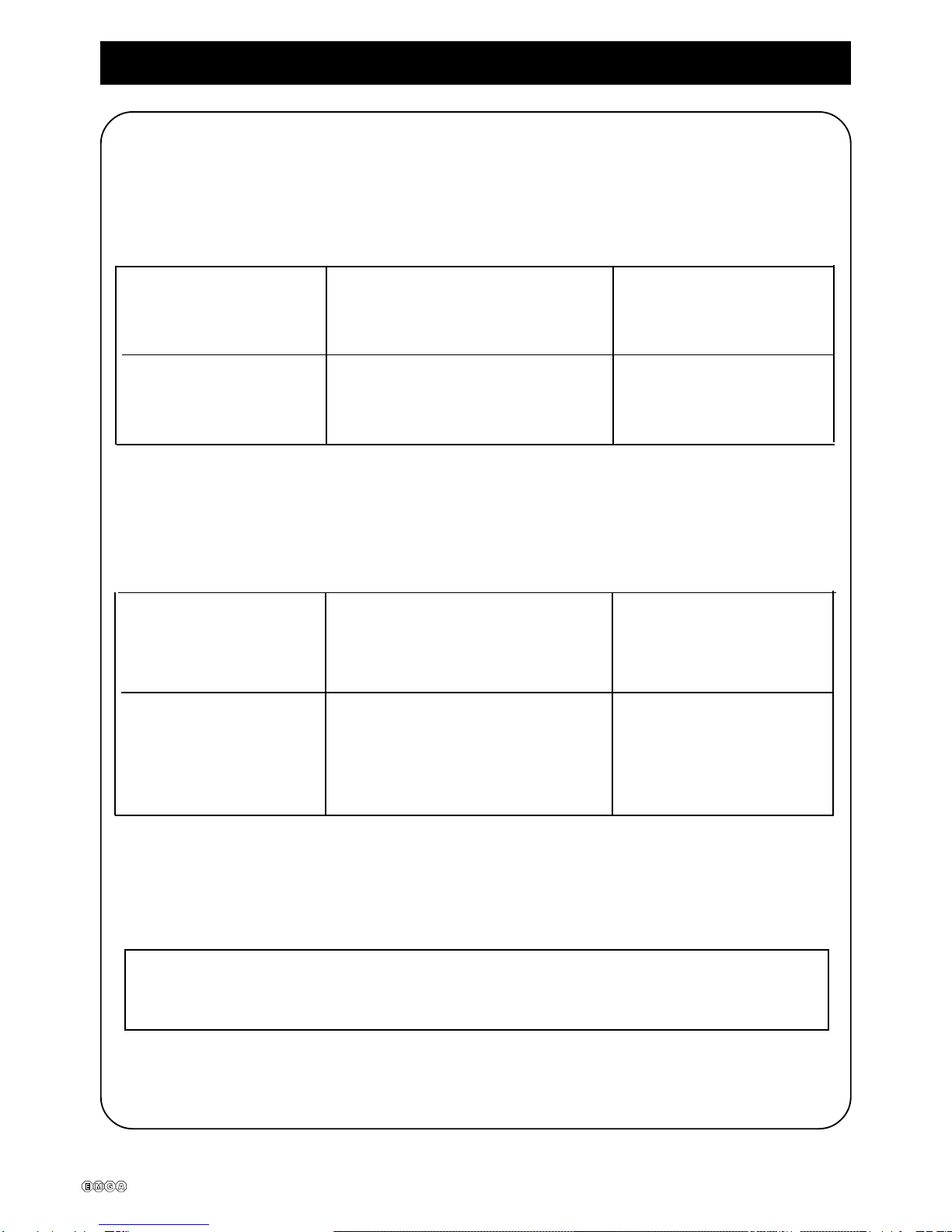
Fault indications - SERVICE
Fault indications E1, E2, E3 and E4 are shown in the display.
NOTE Remove the power plug from the wall during any installation work.
LEVEL CONTROL
TEMPERATURE CONTROL
E1 shown on the display = The level sensor’s short electrode is Clean thelevel sensor.
earthed but not the long one. Replace.
Cables connected incorrectly.
E4 shown on the display = The automat fills slowly. Restart the machine.
Poorwater pressure.
Water tap not open
E2 shown on the display= Temperatureoutsidethe 5°C-105°C.
statedrange
The temperature sensor is broken. Replace.
Cableloose.
E3 shown on the display .enihcamehttratseR.gnolootemitgnitaeH= Solid state broken. Replace.
Element broken. Replace.
Overheatingguardtripped or broken.
NOTE The installation work and all repairs shall be done by a competent
electrician.
320504 en ma 2012 07 9/15
IMPORTANT!
Important.
Donotdoanythingtothehotwaterautomat.Incorrectactioncanleadto personal injury
andfaults.The hot water automat should standonalevelsurfacetoworksatisfactorily.
Thehot water automat must be placedonawaterproofsurfacesothatany water leakage
isvisible.Makesure that kinks are not formed in the connectionhosewhenthehotwater
automat is pushed into place.
Thehotwaterautomat’ssupply and drain connection shallbecheckedregularly.
Checkthatnoleakagehasoccurredinconnectionwithinstallation.
Thewater connection always presents ariskofleakageirrespective of safety equipment.
Neverleavethehotwaterautomatunattended when it isinuse.Turnthetapoffwhenthe
machineis not in use.
Switchoffthesupplybeforeworkingonthehotwaterautomat.Thiscanbedoneby
removingthepowersupplyplugfromthewallsocket.
All installation work must be done by a qualified person.
320504 en ma 2012 07 10/15
Care.
NOTE Cleaning the outside of the machine
Never use aggressive cleaning agents when cleaning the hot water automat.
Use a soft cloth together with a
liquid cleaning agent that does
not scratch.
320504 en ma 2012 07 11/15
Programming.
1. Programming automatic controls for manual water filling.
1.1. FillthewatertoAinthe tank up to the long sensor pin.
See fig. 1.Approximately 4 litres.
1.2. Keep button ( B) pressed and switch on the machine
with theswitch ( D)at the same time.
A
fig.1.
fig.2.
B
C
D
1.3. Thedisplay shows T1
Changethe type of machine with buttonsBor C.
1.4. T1 = HVAautomat
T2= HVM manual
1.5. Confirm the choice by holding down the buttons (B) and (C) at the same time
forapproximately5seconds.
NOTE Install the plug supplied in the inlet valve (E) to avoid possible leakage.
E

320504 en ma 2012 07 12/15
16
2
1
3
4
8
5
7
13
12 11 10
14 15
6
9
Exploded view. HVA
18
19
17
320504 en ma 2012 07 13/15
30 29 28
25
27
26
31
32
33
34
35
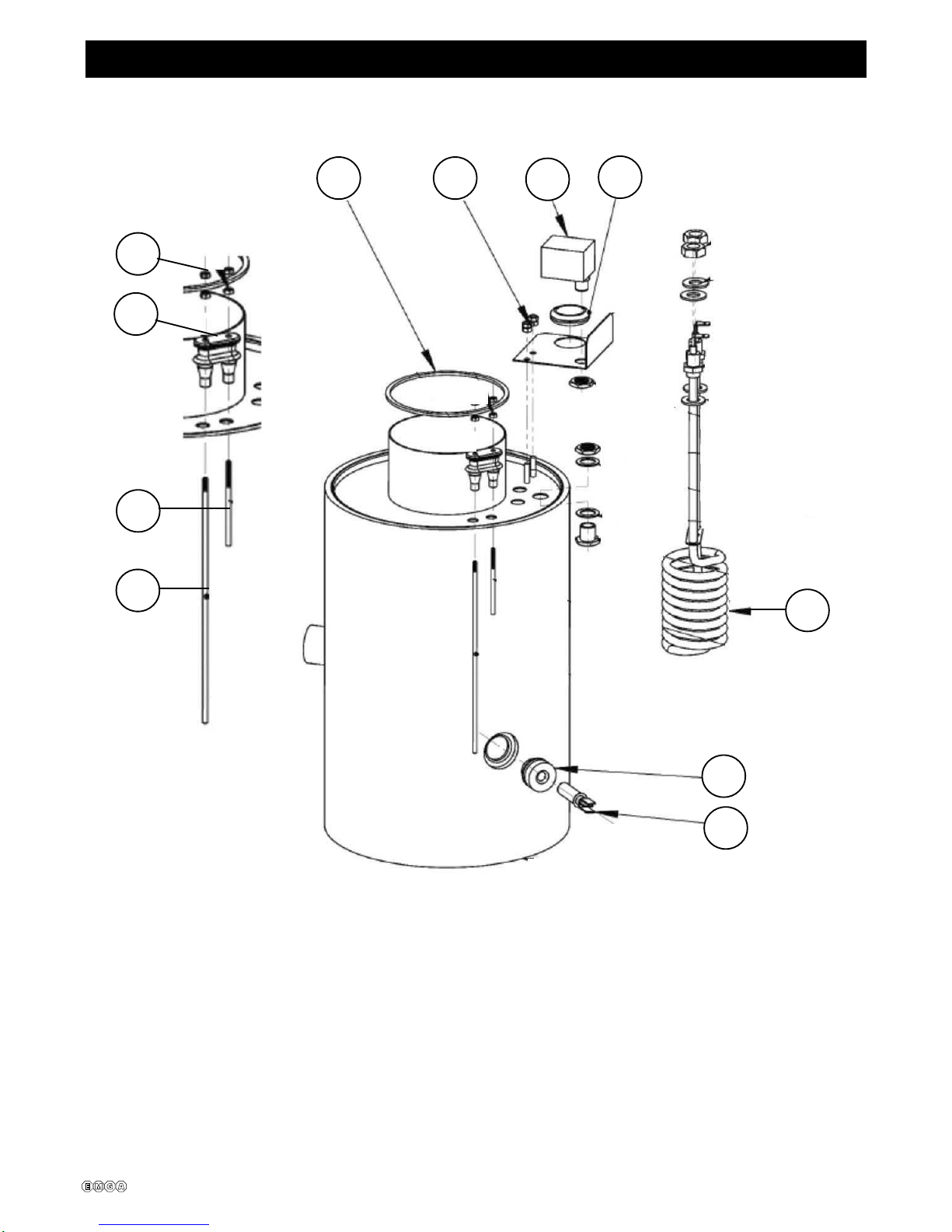
Exploded view Tank complete HVA

320504 en ma 2012 07 14/15
HVA.strapfotsiL
Item Part number Description Qty/unit
1 1304061 1revoccitsalP
2 1304062 Top 1revoc,noitces
3 1203527 T 1etelpmocAVHkna
4 120422 V 1dirgnoitalitne
5 1505022 Cold water hose, silicon L = 1
6 120624-01 Single valve, 2.5 l/m, 230 V 1
7 160801-04 1hctiwS
8 1604203 1etatsdiloS 4tooF-9
10 1031641 1xobscinortcelE
11 1603853 1hctiwsenarbmeM
12 1304063 1yartpirD
13 253207 1tresniyartpirD 1paT20-00202141
15 1802120 Tap 1noitcennoc 1SUS7X3MPNPwercs10
wercS-61
17 1031301 1sselniats,revocedisnI
18 160565 1eporuE/elbactnempiuqE
18 160566 Equipment cable / SouthAfrica 1
18 160567 1KU/elbactnempiuqE
19 160570 1telnisutarappA
——
TANK
25 1604133 1ro
tsimrehtCTN
26 160536 1rotsimrehtCTN,temmorG
27 1601311 Element 2200 W / 230 V HVA SUS 316 1
28 160536 Rubber grommet, TRP 30.0 RUBBER 1
29 220220 1drauggnitaehrevO
30 140108 1SUSmm74MtuN
31 1206589 T 1laeskna
32 140101 1SUS3MtuN
33 1605362 Doublegrommet,level sensor 1
34 1205302 13332trohsniprosneS
35 1205303 Level sensor pin HVAlong 2333 1

320504 en ma 2012 07 15/15
Sketch of dimensions.
Table of contents
Other EMGA Coffee Maker manuals


Popular Coffee Maker manuals by other brands

Coffee Queen
Coffee Queen Future TT Combi automat user manual

BRAYER
BRAYER BR1108 instruction manual

Breville
Breville VCF152X Instructions for use

Gorenje
Gorenje GFACM20S instruction manual

Classic Coffee Concepts
Classic Coffee Concepts RCB130 Instructions for installation, operation, maintenance

Cuisinart
Cuisinart PRC-12 Series Instruction booklet


