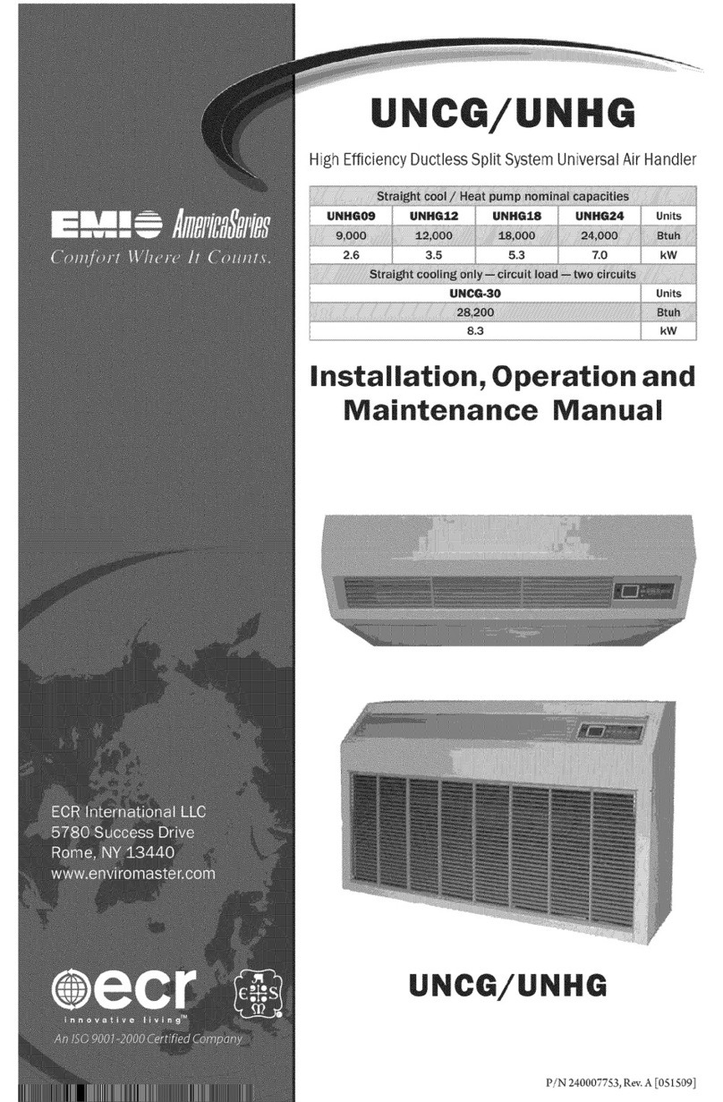
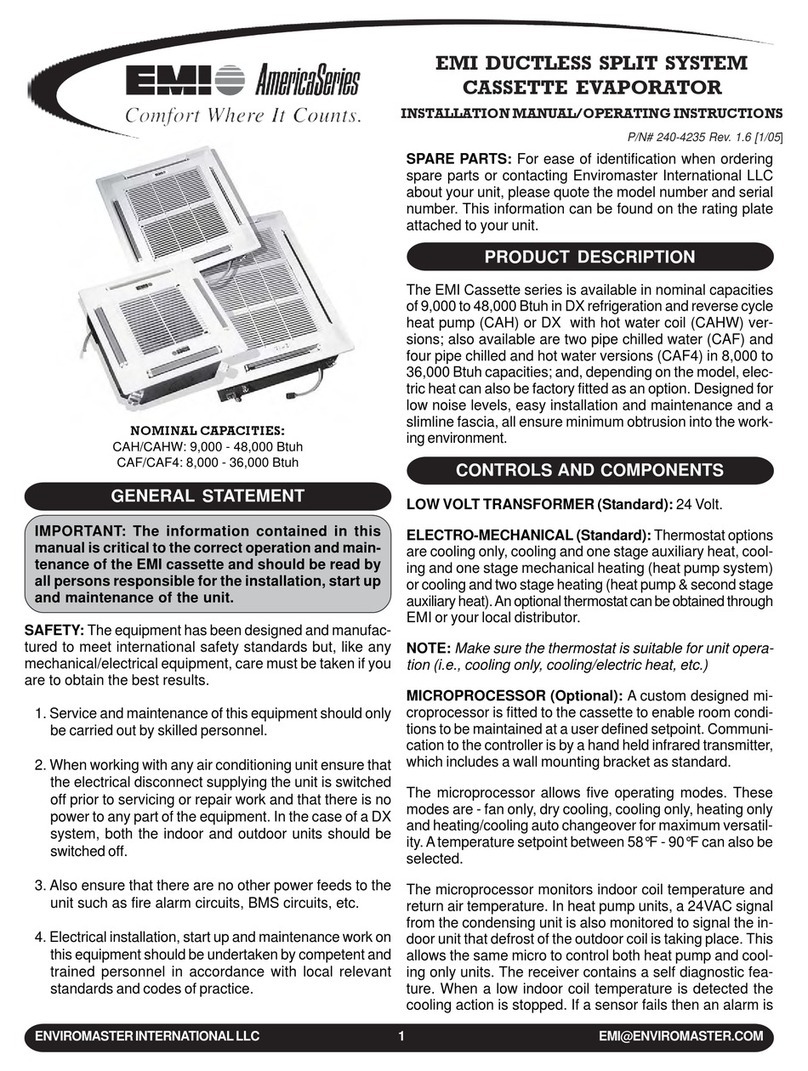
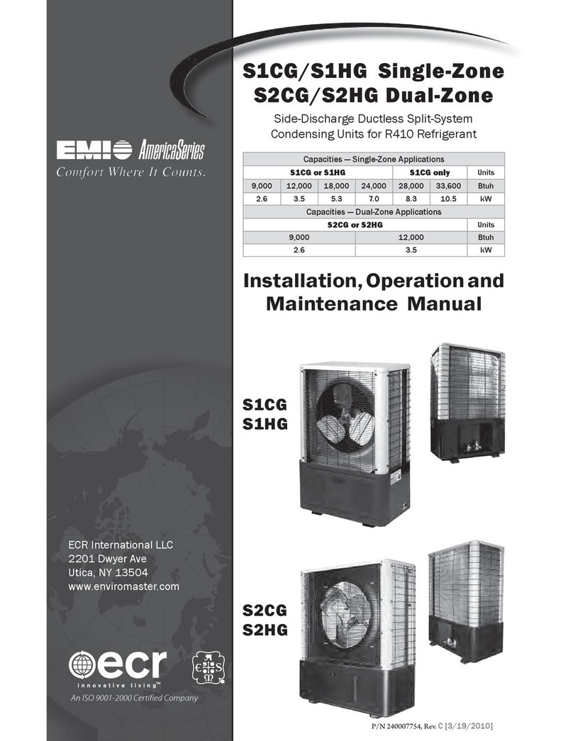
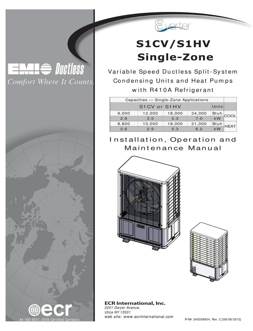
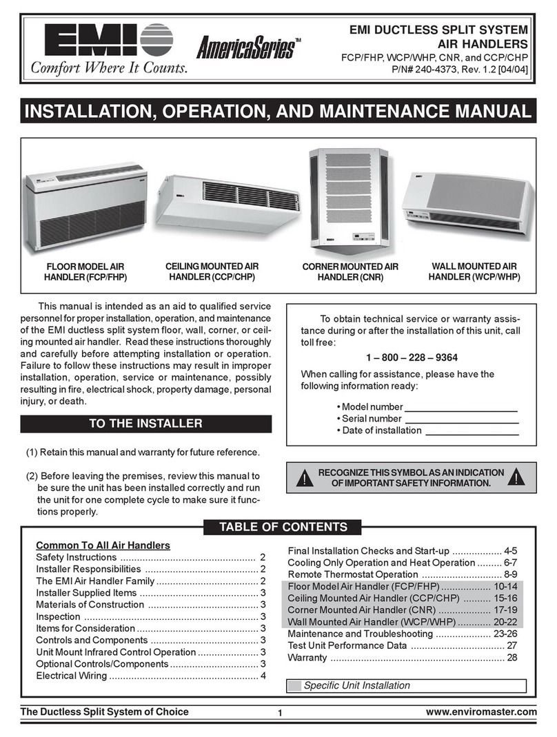
EMI AmericaSeries LLC-09 User manual

The Ductless Split System of Choice Made in Rome, New York, USA
tion on Maximum Range vs. Limited Range Heat
Pumps).
Circuit Numbering:
9 (9,000 BT /h)
2 (12,000 BT /h)
5 (15,000 BT /h)
8 (18,000 BT /h)
4 (24,000 BT /h)
3 (30,000 BT /h)
0 (No Compressor)
The MC/MH2 is only available in three capacities
and only in dual zones. This means you can order any
combination of two circuits in either the MC or MH
units. The capacities are 9, 2, and 5 (as noted above).
With an MC/MH4, you cannot mix and match any
15,000 BT /h or 30,000 BT /h unit with other ca-
pacities in a heat pump (ex: An MC4 2203 is a good
combination while an MH4 2203 is not).
The only capacities available in 4 zones are 9,000,
12,000, and 15,000 BT /h circuits. If an 18,000,
24,000, or 30,000 BT /h capacity is incorporated, the
maximum number of circuits falls to three (3). A unit
model number with three (3) circuits will have a 0
in the model number (ex: MC4 9208). If the capaci-
ties required are any combination of 18,000, 24,000,
or 30,000 BT /h, the number of circuits equals two
(2) and the unit model number will have two zeros
(ex: MC4 0803).
The MC and MH units utilize separate refrigeration
circuits that are independent from each other. Each
circuit has its own compressor and control circuit.
There is one condenser fan that is operating continu-
ously when one or all of the circuits are functioning.
If the heat pump (MH) model is selected, the user can
run one circuit in cooling mode and one in heat mode
if desired.
Air handlers that can be matched with the preceding
condensing units are CAH, CSP/CHP, FSP/FHP, TBH,
and WHP.
SITE INFORMATION/REQUIREMENTS
Do not install units in high traffic areas, drip lines of
roofs, or overhangs.
EMI condensers require a minimum 12 intake air
clearance and 48 discharge air clearance for proper
unit operation. We also recommend a minimum 12
clearance to the side and 48 to the front and rear be-
GENERAL INFORMATION
This guide is intended for use by EMI contractors,
distributors, installers, representatives, and service
technicians to gain a better understanding of EMI Ductless
Split Systems.
This guide will supplement the information found in
the Installation, Operation, & Maintenance Guide and the
Specifications & Performance Guide for your unit. EMI also
publishes Policy Bulletins pertaining to specific installation
and service issues. These bulletins can be found in the full
line catalog and topics include (but are not limited to):
Equipment Matching
Labor Allowances
Return Policies
Run Length/Lift
Tubing Size Requirements
Warehousing Charges
EMI recommends technicians and installers read this
material prior to installing or servicing an EMI Split Sys-
tem. Any questions can be directed to our customer service
department at (315) 336-3716.
SYSTEM DESIGN
EMI manufactures two series of straight-cool
condensing units and limited range heat pumps that can be
matched with any corresponding size EMI-manufactured air
handler.
America Series Single Zone Outdoor Units*
SCC: Models 9-36 (straight cool)
CCB: Models 42-48 (straight cool)
SHC: Models 9-36 (heat pump)
CHD: Models 42-48 (heat pump)
America Series Multi-Zone Outdoor Units**
MC2/MC4: 2-4 Zone (straight cool)
MH2/MH4: 2-4 Zone (heat pump)
* Single Zone indicates that each unit has one compressor to be
connected to a single air handler.
** Multi-zone describes a unit with more than one compressor
for more than one air handler.
EMI manufactures the most extensive line of multi-
zone circuit options in the Ductless Split industry. Due to
running changes and advances, unit decoding and option
availability can become confusing.
The following will answer some Frequently Asked
Questions regarding EMI multi-zone condenser options:
The MH unit is a limited range heat pump (see sec-
DUCTLESS SPLIT SYSTEM
Service and Technical Guide
P/N 240-2985, Rev. 1.2 [07/01]
CLICK ANYWHERE on THIS PAGE to RETURN to HVAC MANUALS & REPAIR GUIDES at InspectApedia.com

2EMI Products are subject to ongoing development. Products & Specifications may change without notice.
tween multiple condensers for ease of service and to
ensure adequate air flow to each unit. Air recircula-
tion can cause high system pressure that could lead to
compressor failure.
Adequate clearance between units is important. If
units are installed too close together, air flow is re-
stricted and this can result in premature compressor
operation or performance problems and failure.
Heat pump models will produce condensate in the
heating mode that will cause water to drain from the
base. When temperatures are below freezing, this wa-
ter becomes ice.
Consider possible icing when installing unit(s) near
sidewalks or walkways.
Heat pumps require airflow clearance in the winter
for heat mode and should be mounted above the level
of maximum anticipated snowfall.
MAXIMUM RANGE VS. LIMITED RANGE
HEAT PUMPS
EMI manufactures 2 types of heat pumps that have
different operating characteristics.
A maximum range heat pump is a standard unitary
industry-style heat pump that utilizes hot gas defrost (reverse
cycle) for continuous heating operation at low ambient
temperatures. tilization of a solid state defrost board,
defrost termination switch, and an outdoor ambient sensor
assists the EMI maximum range heat pump to operate as
designed and tested in mechanical heating mode.
The EMI S C 09-36 & C D 42/48 single zone
series are the maximum range heat pump units that are
presently produced.
The SHC/CHD condenser utilizes a reversing valve
to provide reverse cycle operation. This means that the out-
door unit can act either as a condenser or an evaporator,
thereby providing either comfort cooling or heating to the
indoor space. The reversing valve is energized in cooling.
Therefore, should the valve fail to actuate, the system will
still provide indoor heat.
To check for reversing valve operation, place a jumper
wire across terminals R and O. You should hear a
click to verify that the solenoid is energizing and ac-
tuating the valve.
To check for compressor and condenser fan opera-
tion, place a jumper wire across terminals R and
Y. This will energize the contactor, providing power
to the compressor and condenser fan.
NOTE: If the SHC conden er i equipped with
low ambient fan control for cooling, The fan
will remain off (while in cooling mode) until
the conden er pre ure reache 275p i. The
fan will then energize and run until the
conden er pre ure fall below 210p i. Thi
will happen only in the cooling mode (or when
the rever ing valve i energized). In heating
(rever ing valve not energized), the fan will
run continuou ly o long a the connection i
made between R and Y.
DEFROST CONTROLS WITH SHORT CYCLE PROTECTION
The SHC condenser is equipped with a logic control
circuit designed to keep the system operating at peek effi-
ciency. The 24v circuit provides control to the indoor and
outdoor systems along with 3 minute anti-short cycle com-
pressor protection.
The defrost control circuit is designed to keep the con-
denser coil free from ice and frost during heating mode. This
is accomplished through the precise switching of the out-
door fan, reversing valve, and indoor auxiliary heater.
DEFROST INITIATION
The defrost-sensor is located on either the end plate
or the return bend of the condenser coil. A defrost cycle will
initiate after the sensor closes (approx. 20° F) and remains
closed for the length of time selected on the control board
(Factory setting is 60 minutes for SHC 36 or 90 minutes for
SHC 9-30).
During defrost, the condenser will cycle the reversing
valve and enter a cooling mode. The condenser fan will also
switch off, allowing pressure and temperature to build in
the condenser coil, thereby melting off any ice buildup. At
the same time, the indoor electric heat will energize to
dampen the cold air being discharged from the evaporator
unit. This will continue until either the defrost-sensor opens
(approx. 60° F) or 10 minutes has elapsed. Defrost times
will vary depending on outdoor temperature and moisture
conditions. When defrost is complete the unit will resume
heating.
TESTING DEFROST OPERATION USING TEST PINS
Defrost operation can be checked using the test pins
located on the circuit board of the condensing unit. Defrost
Test Operation will be a time-compressed version of the
actual defrost cycle.
With the system off and using two small alligator
clips, jumper the following sets of test pins:
R and DF2 and DFT TST
Place the indoor unit in heating mode with the set point
temperature well above room temperature to ensure that the
condenser remains on during the entire defrost test operation.
The condenser will operate in heating for

The Ductless Split System of Choice Made in Rome, New York, USA3
approximately 20 seconds. At that point the unit will enter
defrost mode for approximately 2 seconds. During this time
the condenser fan will switch off, the reversing valve will
energize and the defrost board will energize the indoor
electric heat relay through the W terminal. After the 2
second defrost cycle is complete, the unit will switch back
to heating operation for another twenty seconds. This process
will repeat until the jumpers are removed from the test pins.
NOTE: If the conden er coil i heavily fro ted
with ice, it i likely that the Defro t Sen or i
already clo ed o the R and DFT jumper can
be eliminated. To initiate defro t, momentarily
jump DFT TST until the defro t cycle begin
but DO NOT leave the jumper in place. The
unit will remain in defro t mode until the
conden er coil i defro ted and will then
re ume heating mode.
LIMITED RANGE HEAT PUMP
A limited range heat pump is a model that does not
utilize a defrost sequence in heating mode since this unit
will not operate during periods of outdoor temperatures
below 35° F.
The EMI limited range heat pumps are designed to
cease operation at 35° F. (+/- 3° F) and automatically switch
into electric resistance or hydronic heating only, as long as
the evaporator has been supplied with supplemental heat
from the factory (it is recommended that supplemental heat
be ordered as an option with ALL heat pump evaporators).
The specific control that is used to monitor the extreme
cold conditions and break power to the compressor is called
a Changeover Thermostat (C.O. Tstat on wire diagram).
This device has a long sensing bulb on its body that is
strategically placed from the factory for best sensing
capability.
The EMI M 2 & M 4 series condensers are
manufactured as limited range heat pumps. The
capacities available range from 9,000 BTU/h up to 30,000
BTU/h nominal capacity.
MIXING & MATCHING EQUIPMENT IN A
SPLIT SYSTEM (STRAIGHT COOL ONLY)
It is possible to mate EMI air handlers and condensing
units with other manufacturers products in Straight Cool
Applications if the following conditions are met properly
(see EMI Policy Bulletin #910503).
All equipment capacities must have the same BT /h
rating and efficiency rating (SEER).
A transformer must be added to the outdoor unit if
not standard.
If a thermostat is not supplied by EMI it must have
an independent Gsignal capability to operate the fan.
EMI must test and/or approve any non-EMI equip-
ment if heat pump applications require manufacturer
mixing.
NOTE: If EMI equipment i in talled in a mixed
equipment y tem without prior approval, EMI
will void ALL warrantie .
GENERAL WIRING PROCEDURES
EMI systems require the following electrical wiring
for proper operation:
24v transformer (standard in all EMI condensers).
NOTE: It may be nece ary to in tall a tran -
former if u ing another manufacturer traight
cool conden er ( ee Mixing & Matching Equip-
ment in thi guide.)
Indoor and outdoor unit high-voltage supply and ac-
companying wiring must match unit specifications.
If optioned, low voltage thermostat wiring must run
between the indoor and outdoor units (also wall-
mounted thermostat NEC class II wiring).
EMI AmericaSeries condensers are designed to oper-
ate with EMI AmericaSeries evaporators. Both the condenser
(outdoor unit) and evaporator (indoor unit) have a high volt
service connection and are intended to be independently con-
nected to the electrical service panel (see the unit name plate
for correct breaker types and sizes).
The outdoor and indoor units are also connected to
each other through low volt interconnect wiring. A 24v trans-
former located in the condensing unit provides the low volt
power source.
The control circuit operates on a 24v a/c power sup-
ply. Control of the condenser is provided either by the
indoor evaporator unit or a wall mounted remote ther-
mostat.
For example, Model SHC condensing units are de-
signed to independently connect to a high volt power supply
(see name plate for required voltage and circuit breakers).
The high volt connection is made through three 6-inch lead
wires located in the control section (refer to wiring diagram).
Wiring connections must abide by NEC and any local elec-
trical codes.
Low volt connections are made through the 5-posi-
tion terminal located in the control section. This circuit is an
NEC Class-II low volt circuit. The low volt terminal block
is labeled C, Y, O, W2, and R.

4EMI Products are subject to ongoing development. Products & Specifications may change without notice.
CONDENSER OPERATION
The transformer located in the condensing unit pro-
vides 24v control power to both the condenser (outdoor unit)
and the evaporator (indoor unit). The 24v power supply can
be measured across terminals R and C.
NOTE: Follow upplied wiring diagram exactly.
If you plan to upgrade (i.e., add electric heat)
the y tem in the future, it i important to in tall
wiring with the correct amperage rating for
the upgrade.
INTERCONNECT TUBING
se the following guidelines when running suction
and liquid lines.
Maximum tubing run of 100 feet, including 35
feet of lift (see EMI Policy Bulletin).
DO NOT change tubing set size, no matter how long
the run/lift. This is important for proper compressor
oil return. Tubing size is documented in all Specifica
tion Sheets.
NOTE: U e of improper tubing ize will void
the unit warranty.
Always insulate the suction (gas) line. DO NOT in-
sulate the liquid line. The expansion device is in the
evaporator.
Tubing should be run as short and direct as possible.
To avoid oil trapping, tubing should be routed neatly
without any dips in the horizontal runs. Horizontal
suction lines should be pitched down in the direction
of flow with a drop of at least 1/2 per 10 to aid oil
flow.
Install a liquid line filter drier in interconnecting tub-
ing (if not standard). Position it as close to the con-
densing unit as possible. Filter must be a bi flow type
if installed in a heat pump system (see Installing Fil-
ter Driers in this guide).
EMI recommends installation of P-traps in suction
(gas) line vertical lifts (35 max.) at the base, at 15
intervals, and at the top of the tubing run.
P-TRAP INSTALLATION PROCEDURE
Any vertical suction (gas) line riser taller than 4
should have a P-trap installed at the base to facilitate
oil return when the condenser is above the evaporator
(Fig. 1).
When the evaporator is installed above the compres-
sor, the trap will prevent the flow of liquid back to the
compressor in the off cycle.
NOTE: Avoid exce ive oil buildup. The P-trap
hould have a hallow depth and a hort
horizontal ection.
Prefabricated wrought copper traps are available from
your local refrigeration supply warehouse. You may
fabricate one using 2 street elbows and 1 standard
elbow.
P-traps are not required at the foot of the hot gas
risers due to increased oil flow at higher temperatures.
Long vertical risers in suction (gas) lines require
additional traps at the 15 level.
INSTALLING FILTER DRIERS
EMI installs standard filter driers in all 9, 12, and 15
BT /h systems that utilize rotary compressor technol-
ogy (straight cool and heat pump).
Always install a new filter drier whenever the sys-
tem is open for repairs. Make sure to align the arrow
on the liquid line drier with the flow direction for the
unit. se a bi-flow drier for heat pump installation.
NOTE: An additional refrigerant charge will
be nece ary to compen ate for the new filter
drier. Check drier pecification for charge
recommendation .
ANTI-SHORT CYCLE TIMER (ASCT)
Anti-short cycle timer (ASCT) is standard on most
EMI models. It is also available in kit form as necessary.
Consult the factory for the latest information on ASCT.
LOW AMBIENT OPTIONS
Factory installed on heat pump only. Field installed
kit available for cooling only. Components include:
Fan cycle switch and crank case heater (09 ,12, 15)
Fan cycle switch only (18 and up)
Cooling Only- The low ambient option is intended
for use on systems that operate in cooling mode at outdoor
temperatures below 60° F.
Single compressor units utilize a cycling condenser
(Figure 1)
,QVWDOO
7UDS
DW
WKH
WRSRIWKHUXQ
,QVWDOO
DGGLWLRQDO
7UDS
IRUHDFK·RIULVHU
37UDS
DW
IRRW
RI
ULVHU
·
RU
JUHDWHU
3LWFKOLQHLQGLUHFWLRQ
RIUHIULJHUDQWIORZ
PLQLPXPRI´LQ·

The Ductless Split System of Choice Made in Rome, New York, USA5
fan on the high pressure side of the system.
Multiple compressor units also utilize a single cyling
condenser fan on the high pressure side of the system.
The operating range is 210-275 psi. This enables cool-
ing down to approximately 0° F.
NOTE: Multiple compre or unit u e one (1)
fan for all of the compre or .
eat Pump- The low ambient option is available on
single zone heat pump systems. These units also utilize a
single cycling condenser fan, with a relay that allows the
fan to run continuously in heating mode.
Multiple compressor heat pump units use a hot gas
bypass method. The system uses an automatic expan-
sion valve (AXV) to prevent coil freeze up. This al-
lows hot gas to bypass to the suction side under low
ambient conditions.
LOW AMBIENT TROUBLESHOOTING
If the condenser motor cycles rapidly or does not op-
erate at all, check for the following:
Power to the motor
Total system undercharge- System cannot obtain
minimum pressures to signal the motor to cycle (refer
to STG for charging information)
If the unit is charged properly and operating under
low ambient conditions (65° dry bulb F or lower), the
motor should cycle rapidly between 210 (motor off)
and 275 (motor on) psi on the high side.
If the outdoor temperatures coincide with EMI sys-
tem performance charts (65° F and above), in most
cases, the motor will run continuously. In some cases,
under normal operating conditions the motor may have
periods when it will cycle in the 65-75° F temperature
range. This is not abnormal and is not cause for alarm.
CONDENSATE PUMPS & DRAIN
EMI recommends one trap (required on the TBC/TBH
models) for the drain line after it leaves the unit. Never
double trap the drain line. Pour water into the drain pan af-
ter installation to ensure proper drainage.
When installing the condensate line, make certain
the unit is not installed at a distance/height that is
greater than the capability of the factory installed pump
(see Pump Specifications). EMI factory installed
pumps have a maximum lift of 4 feet from the bottom
of the unit.
NOTE: Before completing in tallation, te t
pump action.
EMI offers external pumps for installations that re-
quire more than 4 feet of lift.
SYSTEM TROUBLESHOOTING
If your EMI system does not seem to operate prop-
erly, or the pressure/temperature readings are not correct,
refer to this section and the Troubleshooting Guide in this
manual. Run through the following checklist to properly di-
agnose a problem with your EMI system.
Is the unit switched on?
Are the controls calling for heat or cool?
Is the evap fan running properly?
Is the condenser fan running properly?
Is condenser air flow adequate and unrestricted?
Is the compressor running?
Is subcooling excessive? (see explanation below)
Is superheat too high/low? (see explanation below)
Is the supplied voltage for the unit correct and
within normal tolerances?
Excessive subcooling is caused by non-condensables
(air/water), overcharge, dirty coil, or a restriction. Purge and
draw vacuum to determine if non-condensables are the prob-
lem. If it doesnt solve the problem, remove refrigerant until
subcooling is no longer excessive. If the system was over-
charged, this will solve the problem. If it does not solve the
problem, check superheat readings.
WARNING!! It is illegal to discharge
re rigerant into the atmosphere. Use
proper reclaiming methods & tools when
installing or servicing equipment.
igh superheat is caused by an undercharge, leak,
or restriction. If refrigerant is added to the system to nor-
malize subcooling and the superheat is still high, then there
is a restriction (possible underfeeding expansion device). If
superheat is no longer high, the system was undercharged.
Locate any leaks and repair. When no leaks are found or
remain, recharge the system.
Low superheat (floodback) is caused by an over-
charge, overfeeding expansion device, or inefficient com-
pressor. If refrigerant is removed and both subcooling and
super heat readings are normal, the system was overcharged.
Check the efficiency of the compressor if subcooling is low.
If the compressor is normal, the expansion device is over-
feeding.
NOTE: Conden ing unit built before January
1, 1994, require the ervice panel be placed
over the ervice opening when performing te t
to get true reading .

6EMI Products are subject to ongoing development. Products & Specifications may change without notice.
COMPRESSOR REPLACEMENT
Before replacing the compressor, test it to make sure
it is defective. Check the complete electrical system to the
compressor and its internal electrical system to be sure that
it is not out on internal overload. Reset the manual high pres-
sure switch (if equipped with one).
A complete evacuation of the system must be made
whenever you have a defective compressor or suspect it may
be. If the compressor has been operating for some time, a
careful analysis must be made to determine why the com-
pressor failed.
Many compressor failures are caused by the fol-
lowing conditions:
Poor initial installation of the system.
Changes to the system after installation.
Improper airflow over the evaporator.
Overcharged refrigerant system causing liquid to be
returned to the compressor.
Restricted refrigerant system.
Lack of lubrication (horizontal and excess tubing
must be sloped towards the compressor).
Lack of p-traps in risers.
Liquid refrigerant returning to compressor causing
oil to be washed out of bearings.
Non-condensables such as air and moisture in the
system. Moisture is extremely destructive to a refrig-
erant system.
Acid present in a sealed system.
RECOMMENDED PROCEDURE FOR COMPRESSOR REPLACEMENT
Perform all necessary electrical and refrigeration tests
to be sure the compressor is actually defective before
replacing the compressor.
Be sure power source is off and disconnect all wir-
ing at compressor.
Capture (reclaim) all refrigerant.
After all refrigerant has been captured, disconnect
suction as discharge lines from the compressor and
remove compressor. Be certain to have both suction
and liquid line gauge ports and/or process tube open
to atmosphere.
Disconnect both liquid and suction line connections
at the unit and inspect inside the fittings for any for-
eign particles that may have collected there. (The for-
eign particles can consist of pieces of valves, wind-
ings, or thermal overload particles, and other related
items normally located within the compressor shell.)
If any foreign particles are present, they must be re-
moved.
Carefully capture a small amount of oil from the de-
fective compressor by pouring from the compressor.
NOTE: It i not po ible to pour oil from a
rotary type compre or. On rotary compre or
y tem , oil mu t be collected from the y tem
tubing after properly recapturing refrigerant.
se an acid test kit (one-shot or conventional kit) to
test the oil for acid content according to the instruc-
tions with the kit.
If any evidence of a burnout is found, no matter how
slight, the system should be flushed with nitrogen.
Replace the liquid line filter drier if you have a com-
pressor burnout. It is recommended that the next larger
filter drier be installed and a suction filter drier be
added, following instructions in the filter drier sec-
tion.
REMEMBER: Remove the uction line drier
after a few day of continuou operation.
Install the replacement compressor.
Pressurize with nitrogen and leak test all connec-
tions with a leak detection fluid (i.e., soap). Discharge
nitrogen and repair any leaks found. Repeat until all
leaks are repaired.
Evacuate the system with a vacuum pump capable
of a final vacuum of 200 microns. The system should
be evacuated through both liquid and suction lines and
gauge ports. While the unit is being evacuated, seal
all openings on the defective compressor. Compres-
sor manufacturers will void warranties on received
units that are not properly sealed. Do not distort the
manufacturers tube connections.
Recharge the system with the correct amount of re-
frigerant. se an accurate measuring device, such as
a charging cylinder, electronic scales, or similar de-
vice, if necessary. It is necessary to add additional re-
frigerant to compensate for the volume of the driers
for a basic system charge. See Charging the System
in this manual.

The Ductless Split System of Choice Made in Rome, New York, USA7
Re-test the oil after 48 hours. If acid is still present,
install a new suction drier. If acid is not present, re-
move suction drier.
EVAPORATOR COIL FREEZE-UPS
If your EMI indoor coil freezes in the straight cooling
mode, it is probably caused by one of the following:
System undercharge
Very low primary voltage
Stuck compressor contacts
Refrigeration circuit restriction
Incorrect expansion device (too restrictive)
Very low indoor load (low indoor temperature)
Airflow problem (defective motor, plugged filter, unit
blocked by curtains, furniture, etc.)
Low ambient cooling without low ambient controls.
If the system is asked to cool indoor space while out-
door space is consistently below 60° F, the system must
be fitted with low ambient components. For these
cases, EMI offers an optional low ambient field in-
stalled kit.
NOTE: EMI technical ervice can help you di-
agno e problem with your unit( ). Feel free
to call u Monday through Friday from 8am-
5pm at (315) 336-3716.
CHILLED WATER PIPING (WCP/CCP/FCP)
Standard connections provided are sweat type. See
specifications for line size and actual unit connections.
NOTE: Water pipe ize are given in I.D.
se pipe unions or compression fittings to aide fu-
ture service. se isolation valves to aide in unit re-
moval.
Connections can be brazed or soft-soldered.
Follow manufacturers instructions for any field
installed control valves.
Unit control is provided for a 24v normally closed/
power open valve.
NOTE: Con ult factory if other type of valve
are u ed.
Insulate supply and return piping with closed cell
foam tube insulation.
Avoid necessary bends.
Avoid kinks by using a tubing bender.
Make sure glycol solution is compatible with all
valves, unions, and compression fittings. Ethylene or
propylene is recommended.
Bleed air from system prior to start-up. nits are
equipped with a standard air bleeder on the highest
point of the unit piping.
CAUTION: Di connect power when bleeding
y tem. Make certain liquid doe not contact
any electrical component .
Finish all piping before balancing the system. Bleed
system, adjust temperature and/or water flow rate until de-
sired results are achieved.
The unit filter must be in place and able to be removed
easily for maintenance. To avoid vibration, check chilled
water lines to ensure they are not in contact with each other.
The unit(s) must be mounted securely and level. (See In
stallation, Operation & Maintenance Guide for complete
instructions.)
WSP/WHP & FSP/FHP UNIT MOUNTED
ELECTRONIC CONTROLS (FEATURES)
Large 3/4" LCD Display
Operational range adjustable between 55°and 90° F
in 1.0° increments
Anti-Short Cycle Compressor Protection
Fan Purge (fan remains on for 60 seconds after heat/
cool call is dropped for improved efficiency)
Indoor Coil Freeze Protection (available in Straight
Cool, Cooling Only With Optional Electric Heat, Cool/
Heat Pump With Electric Strip Heat, and Two Stage
Heating).
Fan Operation (Auto, High, Low)
Auto Fan Operation- Automatically selects fan speed
according to heating or cooling demand.
Constant Fan Operation- Manually selected High
or Low Speed.
Optional Hand Held Infrared Controller (a separate
Hand Held Remote used to command the Onboard
Controls).
Test Operation (allows ease of unit testing after in-
stallation by eliminating all timers).
DIPSWITCH SETTINGS
Dipswitches are located in the control section on the
universal relay board. They must be set according to the unit
application (i.e., straight cool, electric heat, heat pump).
The dipswitches must be set prior to installation and
before either the indoor or outdoor units are connected to
power (use the following table as a guide).
Switch 1 2
Cooling Only off off
Cool/Electric Heat on on
All Heat Pumps off on

8EMI Products are subject to ongoing development. Products & Specifications may change without notice.
TEMPERATURESET
POINT ADJUST UP
Button
POWER
ON/OFF Button
TEMPERATURESET
POINT ADJUST DOWN
Button
FANHIGH
Button
FANLOW
Button
AUT OFAN
Button
COOL MODE
Button
FANMODE
Button
OPTIONAL REMOTECONT ROL
BAT T ERIES INCL UDED
POWER, ON/OFF
Button
INFRA-RED SE NSOR
TEMP. SET POINT DOWN
Button
TEMP.SET POINT UP
Button
LCDDisplay
HEAT OPERATION
Indicator
FAN LOW
Indicator
FAN HIGH
Indicator
FAN OPERAT ION
Button
MODE SELECTION
Button
FAN OPERAT ION
Indicator
AUTO FAN
Indicator
COOL ING OPE R AT ION
Indicator
UNIT MOUNTEDCONT ROL
Note: Remove ProtectiveFilmBefore
SecuringCabinet Front
NOTE: Operational range is
55-90° F in 1.0° increments.
CONTROL OPTIONS

The Ductless Split System of Choice Made in Rome, New York, USA9
The control board can be accessed by removing the
return air grill and control box cover with a flat blade screw-
driver or a nutdriver.
NOTE: The microproce or will read the
dip witch etting during power up. If the et-
ting need to be changed, di connect the low
volt power to the evaporator for at lea t 1
minute. In ome ca e thi al o mean witch-
ing the power to the conden er off. Reapply
power for etting to take effect.
TROUBLESHOOTING WSP/WHP & FSP/FHP
UNIT MOUNT INFRARED COMPATIBLE
CONTROL
* When troubleshooting the WHP or FSP FHP units, refer to the
wiring diagram on the back of the removeable return air grill. If
you are unable to locate this diagram, please call (315) 336-3716
and a copy can be faxed or mailed.
EMI AmericaSeries evaporators are designed to oper-
ate with EMI AmericaSeries condensers. Both the evapora-
tor (indoor unit) and condenser (outdoor unit) have a line
volt service connection and are intended to independently
connect to the electrical service panel (see the unit name
plate for the correct breaker type and size).
The indoor and outdoor units are also connected to
each other via 24v interconnect wiring. A transformer lo-
cated in the condensing unit provides the low volt power
source. The number of low volt conductors will be three to
five depending on heating options. Cooling only and cool-
ing with electric heat units have three (3) low volt wires
while heat pumps with electric heat have five.
COOLING ONLY UNITS
On cooling only units there are three low volt wires
on both the indoor and outdoor units. The yellow, red, and
brown wires of the air handler should be connected to the
corresponding yellow, red, and brown wires of the condenser.
A 24v transformer located in the condensing unit provides
low volt control power to both the air handler and condenser.
The 24v power supply can be measured across the red
(R) and brown (C) wires. The air handler will switch on and
off the condenser through the yellow (Y) wire. When the air
handler is calling for cooling, 24v can be measured between
terminals (wires) Y and C.
NOTE: Mo t conden er manufacturer do not
upply low volt tran former with their
conden er . When connecting an EMI
evaporator to a non-EMI conden er, a
tran former may have to be added to the
y tem to provide 24v power.
COOLING ONLY WITH ELECTRIC HEAT UNITS
nits with electric heat have a strip heater located
behind the evaporator coil. The control relay for the heater
in located on the circuit board in the control box. A limit
switch located on the heater end plate will interrupt power
to the heater should the airflow become compromised. If
temperatures rise above the limit setting a non-resetting one
time fuse link will burn and the heater will remain off.
The following current values apply when the unit is
connected to a 230v power supply. These values include fan
motor current:
3kw (13.5 amps)
4 kw (18 amps)
5kw (22.3 amps)
HEAT PUMP WITH ELECTRIC HEAT
Heat pump units with electric heat have five intercon-
necting low volt wires on both the indoor and outdoor units.
The yellow, red, white, orange, and brown wires of the air
handler should be connected to the corresponding yellow,
red, white, orange, and brown wires of the condenser. A 24v
transformer located in the condensing unit provides low volt
control power to both the air handler and condenser.
With high volt power supplied to the condenser, 24v
can be measured across the red (R) and brown (C) wires at
all times.
COOLING
The air handler will cycle the condenser on and off
through the yellow (Y) wire. To check for a condenser sig-
nal, place the indoor unit in cooling mode and choose a
setpoint temperature that is below room temperature. Then,
with a voltmeter, check for 24 volts across the yellow (Y)
and brown (C) wires.
EMIs heat pump systems utilize a reversing valve is
that is energized in the cooling mode. The reversing-valve
signal is provided through the orange (O) low volt wire. It
will remain energized constantly as long as the unit remains
in cooling mode. To check for 24v reversing valve voltage,
place a voltmeter across the brown (C) and orange (O) wires
while the indoor unit is in the cooling mode.
Image of Dipswitch on Control Board

0EMI Products are subject to ongoing development. Products & Specifications may change without notice.
HEATING
This unit is designed to utilize two-stage heating. The
first stage being the compressor and the second electric heat.
The air handler will cycle the condenser on and off through
the yellow (Y) wire as it does in cooling; however; the re-
versing valve will not be energized. To check for a con-
denser signal:
Step 1- Place the indoor unit in heating mode with the
Mode button.
Step 2- sing the Up arrow, place the setpoint tem-
perature one degree above room temperature.
Step 3- With a voltmeter, check for 24 volts across the
yellow (Y) and brown (C) wires. The electric heat
should be off at this point.
Step 4- With the Up arrow, select a setpoint tempera-
ture that is more than two degrees above the room tem-
perature. The electric heat should energize along with
the 24v compressor signal between Y and C. Check to
see that the amp draw corresponds with the electric
heat rating.
The following current values apply when the unit is
connected to a 230v power supply. These values include fan
motor current:
3kw (13.5 amps)
4kw (18 amps)
5kw (22.3 amps)
nits with electric heat have a strip heater located be-
hind the evaporator coil. The control relay for the heater in
located on the circuit board in the control box. A limit switch
located on the heater end plate will interrupt power to the
heater should the airflow become compromised. If tempera-
tures rise above the limit, setting a non-resetting one-time
fuse link will burn and the heater will remain off.
UNITS WITH CONDENSATE PUMPS
Models WSP or WHP are available with an optional
condensate pump. Condensate pumps are recommended
when it is not possible to gravity drain the condensation from
the indoor unit. The condensate pump is located behind the
front control panel and has a maximum lift capability of 4
feet from the base of the unit.
NOTE: Conden ation generated by the
evaporator will collect in the pump re ervoir.
When the water level i high enough, a float
witch will clo e and energize the pump,
clearing the water from the re ervoir. Should,
for any rea on, the water exceed the maximum
pre et level, a econdary float will open a afety
witch, thereby cutting the (Y) ignal to the
conden er. Thi will prevent the evaporator
from generating more conden ation and
pilling out of the unit.
FREEZE PROTECTION
The indoor fan coil unit is protected in the event of
freeze up. If the evaporator falls below 32° F for more than
three minutes, the compressor is forced off. When the evapo-
rator temperature returns to 50° F, normal cooling opera-
tion resumes. If the evaporator returns to above 32° F but
remains below 50° F for 10 minutes, cooling operation will
also resume.
OPERATIONAL MODES
- Fan only
- Cooling only
- Cooling with optional indoor electric strip heat
- Cooling/Heatpump with optional electric strip heat
ON/OFF SWITCH
The On/Off switch is used to turn the equipment on or
off. In the Off mode, the LCD will be blank and all LED
indicator lights will be dark. To turn the unit on press the
On/Off button once. The LCD will display the room tem-
perature and LED indicators will light up to show fan speed
and mode selection.
INITIAL STARTUP
pon initial power-up the unit will start in Fan only
mode at High speed. These are the default settings of the
microprocessor. Once temperature and mode selections have
been made, they will be stored in the microprocessor memory
when the unit is switched off. The next time the unit is
switched back on via the On/Off switch, the stored settings
will be used and the unit will resume operation. If power is
lost, the equipment will return to an Off state (if it was on)
and any temperature or mode settings will be lost.
MODE SWITCH (SYSTEM SWITCH)
The Mode button will allow the selection of the de-
sired mode. Colored LED indicators will light next to the
selected mode. With each successive press of the Mode but-
ton, selection will rotate between Heat, Cool and Fan. There
is a 7 second time delay after the mode button is released
before the execution of the selection to prevent the unit from
starting prematurely.
FAN OPERATION
These units utilize a two-speed motor with three op-
erational fan modes. The Fan button will allow the selec-
tion of the desired fan mode. With each successive press of
the Fan button, selection will rotate between High, Low, and
Auto. In Fan mode, Auto is bypassed and only High or Low
are available. An amber LED indicator will light next to the
fan speed selection. If Auto fan speed is selected then an
LED indicator will also light next to Auto. High and Low
selections are constant fan settings.

The Ductless Split System of Choice Made in Rome, New York, USA
Auto fan mode can only be selected if the unit is in
Heat or Cool. In Auto mode the fan will cycle with the call
for Heat or Cool. Fan speed will be determined by the mi-
croprocessor and speed adjustments will be made according
to room temperature and setpoint. The fan will switch to
High speed when room temperature deviates by more than
2° F from setpoint. The fan will switch to low speed if the
deviation is 1° F. When the room temperature reaches
setpoint temperature the heat/cool call is dropped. The fan
will then stay on for an additional 60 seconds to purge the
unit of any residual energy.
COOLING ONLY OPERATION
To select Cool mode, turn the unit on via the On/Off
switch. The LCD will display room temperature. Select Cool
mode via the Mode button. Then, by depressing either the
Up or Down arrow once, the setpoint temperature will ap-
pear in the LCD display. The setpoint temperature can then
be changed with each successive press of the Up or Down
arrow or by holding the button in. Place the setpoint tem-
perature below the room temperature. The compressor will
start and cooling will continue as long as the setpoint is be-
low the room temperature.
Once room temperature is satisfied, the compressor
will cycle off. The fan will operate as described in Fan
Operation. Once the compressor is switched off (or if power
is lost), there is a three-minute delay before restarting.
OPTIONAL ELECTRIC HEAT OPERATION (STRAIGHT COOL
UNITS ONLY)
To select Heat mode, turn the unit on with the On/Off
switch. The LCD will display room temperature. Select Heat
mode via the Mode button. Then, by depressing either the
Up or Down arrow once, the setpoint temperature will ap-
pear in the LCD display. The setpoint temperature can then
be changed with each successive press of the Up or Down
arrow or by holding the button in. The electric heat will en-
ergize and heating will continue as long as the setpoint is
above the room temperature. The fan will operate as de-
scribed in Fan Operation.
OPTIONAL HEAT PUMP WITH ELECTRIC HEAT (2-STAGE
HEATING)
To select Heat mode, turn the unit on with the On/Off
switch. The LCD will display room temperature. Select Heat
mode via the Mode button. Then, by depressing either the
Up or Down arrow once, the setpoint temperature will ap-
pear in the LCD display. The setpoint temperature can then
be changed with each successive press of the Up or Down
arrow or by holding the button in. Place the setpoint tem-
perature above the room temperature. The compressor will
start heating and run as long as the setpoint is above the
room temperature.*
* Some EMI heat pump condensers are equipped with a low tem-
perature cutout that will shut down the compressor & energize the
indoor electric heat when outdoor temperatures fall below 0° F.
Once the room temperature is satisfied, the compres-
sor will cycle off. The fan will operate as described in Fan
Operation. Once the compressor is switched off (or power
is lost), there is a three-minute delay before it will re-start.
Should the room temperature fall more than 2° F below the
setpoint, the electric heat will energize along with the heat
pump (2-stage heating).
The electric heat will continue to run until the devia-
tion between room temperature and setpoint temperature is
less than 2° F. At that time the electric heat is switched off
and the heat pump will take over the heating demand. This
will continue until the room temperature reaches setpoint
temperature and heating demand is satisfied. The fan will
operate as described in Fan Operation.
CHARGING EMI SPLIT SYSTEMS
EMI publishes a variety of charts that are to be used
as a general guideline for properly charging EMI systems.
We make available the following Charge Tables and Op-
eration Charts to assist the installer at time of startup.
It is very important to note that they should be utilized
whenever starting up a complete EMI Split System combi-
nation. However, there are a wide range of variables that
will cause your readings to deviate from published data some-
what.
NOTE: EMI highly recommend u ing the Su-
perheat value from the Operation Chart a
a final fine-tune of y tem charge.
RECOMMENDED SYSTEM CHARGING PROCEDURE
Step 1- Following proper evacuation (to 200 microns
or less), release factory charge from condenser
throughout the system by backseating the refrigerant
valves. This is enough refrigerant for a system that
has little to no interconnect (enough refrigerant for
condenser and evaporator only).
Step 2- se supplied Refrigerant Charge Tables for
deciding how much refrigerant you will need to weigh
into your system to bring it close to optimum. EMI
recommends that, when weighing in refrigerant per
chart information, you initially leave the charge short
(3-5 ounces) as your exact combination or ambient
conditions may cause a small deviation from chart
value.
Step 3- With your refrigerant gauges on the system
high and low side, let the system settle out and compare
values to the supplied Operation Chart values for
your combination. You can now fine tune your system
charge by adding (or reclaiming) enough refrigerant

2EMI Products are subject to ongoing development. Products & Specifications may change without notice.
PHONE:(315)336-3716
FAX:1-800-232-9364
to obtain values of Suction/Discharge pressures and
Superheat/Subcooling.
Note the Superheat value before disconnecting the
system. All EMI systems are designed to operate at
optimum capacity and efficiency when running 10° F
Superheat (+/- 2° F) at ARI rating condition of 80/67°
F indoors and 95° F outdoors. Since most startups are
not done at these exact conditions, it is critical to follow
the superheat chart values for given outdoor conditions
when fine tuning the system charge. The other values
should be close under most conditions.
REMOTE THERMOSTAT PLACEMENT
EMI systems can be installed with remote mounted
(wall) thermostat control (24v Class-II low voltage circuit).
se a thermostat that will provide a signal to the G termi-
nal.
NOTE: A ignal mu t be pre ent at the G
terminal to operate the evaporator fan in heat
mode.
The thermostat should be mounted 60 inches from the
floor on a warm (i.e., INSIDE) or post away from doors,
drafts, or high traffic areas.
FIELD INSTALLED KITS
EMI provides certain kits to modify your existing unit.
We have kits available for widespread use in EMI systems,
including:
Low Ambient Kits (cooling only- ALWAYS field in-
stalled)
Hard Start Kits (ALWAYS field installed)
Condensate Pump Kits (field installed for certain
evaporator models)
Specific Control Changeover Kits (i.e., nit Mount
to Remote T-stat) for some older model EMI evapo-
rators.
Consult factory technical service representative to
choose the exact kit that you will need for your EMI model
unit. Kits change periodically so a kit that worked in one
model year may not work for a unit manufactured in a dif-
ferent model year.
NOTE: EMI doe not tock or recommend
electric heat add-on kit for field in tallation.
It i critical that, if you can fore ee the need
for electric heat in your EMI evaporator, you
initially order it a a factory in talled option.
Adding an electric heater in the field has proved to be
complicated and difficult due to space constraints and/or
the unit being mounted into position already.
EMI will not accept responsibility for the rework per-
formed. EMIs safety approval listing (ETL) becomes void
at the time a field rework that involves an electric heater
takes place since several items, including breaker size, wire
size, and unit rating are immediately effected.
SYSTEM DATA
If, after routine inspection and adjustments, the sys-
tem is not performing up to standards, call EMI Customer
Service for assistance. It is important that the System Data
Form (see following page) be completely filled out and, if
possible, FAXED to our service group at 1-800-232-9364.
With this information in hand, we can prepare to help you
and handle the situation in a timely and effective manner.
Complete parts listings are available from your dis-
tributor or from the EMI factory. All parts orders must be
entered with the distributor who supplied the original equip-
ment order. If assistance is needed for identifying a part num-
ber or description, please call EMI Customer Service.
When calling EMI for service assistance and/or parts
orders, you will need to provide the complete unit model
number and serial number as obtained from the rating plate
attached to the equipment.
For your convenience, this space is provided to record
the necessary information specified above. Please complete
this section at the time of installation:
Model#: _________________________
Serial #: _________________________
Install Date:_________________________

The Ductless Split System of Choice Made in Rome, New York, USA3
SYSTEM DATA SHEET
Model# (Condenser): _________________________ Air andler: _________________________
Serial# (Condenser): _________________________ Air andler: _________________________
Mode: eating Cooling
Outdoor Ambient: ___________dry bulb___________wet bulb
Indoor Ambient: ___________dry bulb___________wet bulb
Temperature Entering Evap Coil: ________________________________________
Temperature Leaving Evap Coil (supply air temperature): ___________________
Suction Pressure: ______________________________________________________
Discharge Pressure: ____________________________________________________
Superheat: ___________________________________________________________
Liquid Line Temperature: ______________________________________________
Subcooling: ___________________________________________________________
Suction Temperature at Compressor: _____________________________________
Voltage (Running): ____________________________________________________
AMP Draw: __________________________________________________________
Run Length: __________________________________________________________
Run Lift: _____________________________________________________________
Line Size: ________Liquid_________Suction _______
Indoor Motor Volts: ________________ ign Speed CFM: ____________________
Indoor Motor Amps: _______________ Low Speed CFM: ____________________
Indoor Motor RPM: _______________
Brief Job istory: _____________________________________________________
_____________________________________________________________________
_____________________________________________________________________
_____________________________________________________________________

4EMI Products are subject to ongoing development. Products & Specifications may change without notice.
REFRIGERANT CHARGE TABLES - AA SYSTEMS SINGLE ZONE (STRAIGHT COOL)
To determine charge adju tment and y tem charge for
any evaporator and tubing length:
Total Adju tment= (Line Charge/FT) x Line Length
Sy tem Total= Factory Charge +Total Adju tment c
pavE
ledoM
eniL
TF/GHC
eniL
htgneL
)tf(
latoT
tsujdA
yrotcaF
egrahC
etsyS
latoT
90-WCL.zo52.
01
52
05
.zo3
.zo6
.zo31
zo72
.zo03
.zo33
.zo04
LCC-09
pavE
ledoM
eniL
TF/GHC
eniL
htgneL
)tf(
latoT
tsujdA
yrotcaF
egrahC
etsyS
latoT
21-WCL.zo52.
01
52
05
.zo3
.zo6
.zo31
zo03
.zo33
.zo63
.zo34
LCC-12
pavE
ledoM
eniL
TF/GHC
eniL
htgneL
)tf(
latoT
tsujdA
yrotcaF
egrahC
etsyS
latoT
51-WCL.zo52. 015205
.zo3 .zo6 .zo31 zo03 .zo33 .zo63 .zo34
LCC-15
pavE
ledoM
eniL
TF/GHC
eniL
htgneL
)tf(
latoT
tsujdA
yrotcaF
egrahC
etsyS
latoT
81-WCL.zo65. 015205
.zo6 .zo41 .zo81 zo64 .zo25 .zo06 .zo46
LCC-18
pavE
ledoM
eniL
TF/GHC
eniL
htgneL
)tf(
latoT
tsujdA
yrotcaF
egrahC
etsyS
latoT
42-WCL.zo65. 015205
.zo6 .zo41 .zo81 zo94 .zo55 .zo36 .zo76
LCC-24
NOTE: Round down to nearest ounce and allow or gauges and hoses.

The Ductless Split System of Choice Made in Rome, New York, USA5
REFRIGERANT CHARGE TABLES - SINGLE ZONE (STRAIGHT COOL)
pavE
ledoM
eniL
TF/GHC
eniL
htgneL
)tf(
latoT
tsujdA
yrotcaF
egrahC
-etsyS
latoT
42-PHC/PSC 42-PHW/PSW 42-PHF/PSF 42HAC
.zo65. 015205
.zo6 .zo41 .zo82 zo05 .zo65 .zo46 .zo87
SCC-24
pavE
ledoM
eniL
TF/GHC
eniL
htgneL
)tf(
latoT
tsujdA
yrotcaF
egrahC
etsyS
latoT
21-PHC/PSC 21-PHW/PSW 21-PHF/PSF 21-H/CBT 21HAC
.zo52. 015205
.zo3 .zo6 .zo31 zo5.92 .zo23 .zo53 .zo24
SCC-12
pavE
ledoM
eniL
TF/GHC
eniL
htgneL
)tf(
latoT
tsujdA
yrotcaF
egrahC
etsyS
latoT
51-PHC/PSC 51-PHW/PSW 51-PHF/PSF 51-H/CBT 51HAC
.zo52. 015205
.zo3 .zo6 .zo31 zo5.34 .zo5.64 .zo5.94 .zo5.65
SCC-15
pavE
ledoM
eniL
TF/GHC
eniL
htgneL
)tf(
latoT
tsujdA
yrotcaF
egrahC
etsyS
latoT
42-PHC/PSC 42-PHW/PSW 42-PHF/PSF 42-H/CBT 42HAC
.zo65. 015205
.zo6 .zo41 .zo82 zo53 .zo14 .zo94 .zo36
SCC-18
SCC-09
pavE
ledoM
eniL
TF/GHC
eniL
htgneL
)tf(
latoT
tsujdA
yrotcaF
egrahC
etsyS
latoT
21-PHC/PSC 21-PHW/PSW 21-PHF/PSF 21-H/CBT 21HAC
.zo52. 015205
.zo3 .zo6 .zo31 zo5.62 .zo92 .zo23 .zo93
pavE
ledoM
eniL
TF/GHC
eniL
htgneL
)tf(
latoT
tsujdA
yrotcaF
egrahC
etsyS
latoT
03-PHC/PSC 03-PHW/PSW 03-PHF/PSF 03HAC
.zo65. 015205
.zo6 .zo41 .zo82 zo46 .zo07 .zo87 .zo29
SCC-30
pavE
ledoM
eniL
TF/GHC
eniL
htgneL
)tf(
latoT
tsujdA
yrotcaF
egrahC
etsyS
latoT
63-PHC/PSC 63-PHW/PSW 63-PHF/PSF 63HAC
.zo65. 015205
.zo6 .zo41 .zo82 zo56 .zo17 .zo17 .zo39
SCC-36
pavE
ledoM
eniL
TF/GHC
eniL
htgneL
)tf(
latoT
tsujdA
yrotcaF
egrahC
etsyS
latoT
24-PHC/PSC 24-PHW/PSW 24-PHF/PSF 24HAC
.zo56. 015205
.zo7 .zo61 .zo33 zo101 .zo801 .zo711 .zo431
CCB-42
To determine charge adju tment and y tem charge
for any evaporator and tubing length:
Total Adju tment= (Line Charge/FT) x Line Length
Sy tem Total= Factory Charge +Total Adju tment
NOTE: Round down to nearest ounce and allow
or gauges and hoses.
pavE
ledoM
eniL
TF/GHC
eniL
htgneL
)tf(
latoT
tsujdA
yrotcaF
egrahC
etsyS
latoT
84-PHC/PSC 84-PHW/PSW 84-PHF/PSF 84HAC
.zo476. 015205
.zo7 .zo71 .zo43 zo201 .zo901 .zo911 .zo631
CCB-48

6EMI Products are subject to ongoing development. Products & Specifications may change without notice.
REFRIGERANT CHARGE TABLES - SINGLE ZONE (HEAT PUMP)
pavE
ledoM
eniL
TF/GHC
eniL
htgneL
)tf(
latoT
tsujdA
yrotcaF
egrahC
etsyS
latoT
90-PHC 90-PHF 90-PHW 90-HBT 90-HAC
.zo52. 015205
.zo3 .zo6 .zo31 zo44 .zo74 .zo05 .zo75
S C-09
pavE
ledoM
eniL
TF/GHC
eniL
htgneL
)tf(
latoT
tsujdA
yrotcaF
egrahC
etsyS
latoT
03-PHC 03-PHF 03-PHW 03-HAC
.zo65. 015205
.zo6 .zo41 .zo82 zo86 .zo47 .zo28 .zo39
S C-30
pavE
ledoM
eniL
TF/GHC
eniL
htgneL
)tf(
latoT
tsujdA
yrotcaF
egrahC
etsyS
latoT
63-PHC 63-PHF 63-HAC .zo65. 015205
.zo6 .zo41 .zo82 .zo56 .zo17 .zo97 .zo39
S C-36
To determine charge adju tment and y tem charge
for any evaporator and tubing length:
Total Adju tment= (Line Charge/FT) x Line Length
Sy tem Total= Factory Charge +Total Adju tment
NOTE: Round down to nearest ounce and allow
or gauges and hoses.
EX- MC4-24/CSP-24 with 18 line length
(.56) 18= 10oz. ( otal Adjustment)
60oz.+10oz.= 70oz. (System otal)
pavE
ledoM
eniL
TF/GHC
eniL
htgneL
)tf(
latoT
tsujdA
yrotcaF
egrahC
etsyS
latoT
21-PHC 21-PHF 21-PHW 21-HBT 21-HAC
.zo52. 015205
.zo3 .zo6 31 .zo
.zo24 .zo54 .zo84 .zo55
S C-12
pavE
ledoM
eniL
TF/GHC
eniL
htgneL
)tf(
latoT
tsujdA
yrotcaF
egrahC
etsyS
latoT
51-PHC 51-PHF 51-PHW 51-HBT 51-HAC
.zo52. 015205
.zo3 .zo6 .zo31 .zo84 .zo15 .zo45 .zo16
S C-15
pavE
ledoM
eniL
TF/GHC
eniL
htgneL
)tf(
latoT
tsujdA
yrotcaF
egrahC
etsyS
latoT
24-PHC 24-PHF 24-HAC .zo56. 015205
.zo7 .zo61 .zo33 .zo101 .zo801 .zo711 .zo431
C D-42
pavE
ledoM
eniL
TF/GHC
eniL
htgneL
)tf(
latoT
tsujdA
yrotcaF
egrahC
etsyS
latoT
42-PHC 42-PHF 42-PHW 42-HBT 42-HAC
.zo65. 015205
.zo6 .zo41 .zo82 zo14 .zo74 .zo55 .zo96
S C-18
pavE
ledoM
eniL
TF/GHC
eniL
htgneL
)tf(
latoT
tsujdA
yrotcaF
egrahC
etsyS
latoT
84-PHC 84-PHF 84-HAC .zo476. 015205
.zo7 .zo71 .zo43 zo201 .zo901 .zo911 .zo631
C D-48
pavE
ledoM
eniL
TF/GHC
eniL
htgneL
)tf(
latoT
tsujdA
yrotcaF
egrahC
etsyS
latoT
42-PHC 42-PHF 42-PHW 42-HBT 42-HAC
.zo65. 015205
.zo6 .zo41 .zo82 zo44 .zo05 .zo85 .zo27
S C-24

The Ductless Split System of Choice Made in Rome, New York, USA7
REFRIGERANT CHARGE TABLES- MULTI-ZONE
(STRAIGHT COOL)
REFRIGERANT CHARGE TABLES- MULTI-ZONE
(HEAT PUMP)
ledoMpavE eniL
TF/GHC
eniL
htgneL
)tf(
latoT
tsujdA
yrotcaF
egrahC
etsyS
latoT
21-PHC 21-PHF 21-PHW 21-HAC
52. 015205
.zo3 .zo6 .zo31 .zo92 .zo23 .zo53 .zo24
M -09/12
ledoMpavE eniL
TF/GHC
eniL
htgneL
)tf(
latoT
tsujdA
yrotcaF
egrahC
etsyS
latoT
51-PHC/PSC 51-PHF/PSF 51-PHW/PSW 51-H/CBT 51-HAC
52. 015205
.zo3 .zo6 .zo31
5.93 .zo
.zo24 .zo54 .zo25
MC-15
ledoMpavE eniL
TF/GHC
eniL
htgneL
)tf(
latoT
tsujdA
yrotcaF
egrahC
-etsyS
latoT
51-PHC 51-PHF 51-PHW 51-HAC
52. 015205
.zo3 .zo6 .zo31 .zo54 .zo84 .zo15 .zo85
M -15
ledoMpavE eniL
TF/GHC
eniL
htgneL
)tf(
latoT
tsujdA
yrotcaF
egrahC
etsyS
latoT
42-PHC/PSC 42-PHF/PSF 81-PHW/PSW 42-H/CBT 42-HAC
65. 015205
.zo6 .zo41 .zo82 .zo53 .zo14 .zo94 .zo36
MC-18
ledoMpavE eniL
TF/GHC
eniL
htgneL
)tf(
latoT
tsujdA
yrotcaF
egrahC
etsyS
latoT
42-PHC/PSC 42-PHF/PSF 42-PHW/PSW 42-H/CBT 42-HAC
65. 015205
.zo6 .zo41 .zo82 .zo14 .zo74 .zo55 .zo96
M -18
ledoMpavE eniL
TF/GHC
eniL
htgneL
)tf(
latoT
tsujdA
yrotcaF
egrahC
etsyS
latoT
42-PHC/PSC 42-PHF/PSF 42-PHW/PSW 42-H/CBT 42-HAC
65. 015205
.zo6 .zo41 .zo82 .zo44 .zo05 .zo85 .zo27
MC-24
ledoMpavE eniL
TF/GHC
eniL
htgneL
)tf(
latoT
tsujdA
yrotcaF
egrahC
etsyS
latoT
42-PHC 42-PHF 42-PHW 42-HAC
65. 015205
.zo6 .zo41 .zo82 .zo54 .zo15 .zo95 .zo37
M -24
ledoMpavE eniL
TF/GHC
eniL
htgneL
)tf(
latoT
tsujdA
yrotcaF
egrahC
etsyS
latoT
03-PHC/PSC 03-PHF/PSF 03-PHW/PSW 03-H/CBT 03-HAC
65. 015205
.zo6 .zo41 .zo82 .zo46 .zo07 .zo87 .zo29
MC-30
ledoMpavE eniL
TF/GHC
eniL
htgneL
)tf(
latoT
tsujdA
yrotcaF
egrahC
etsyS
latoT
03-PHC 03-PHF 03-PHW 03-HAC
65. 015205
.zo6 .zo41 .zo82 .zo86 .zo47 .zo28 .zo69
M -30
ledoMpavE eniL
TF/GHC
eniL
htgneL
)tf(
latoT
tsujdA
yrotcaF
egrahC
etsyS
latoT
21-PHC/PSC 21-PHF/PSF 21-PHW/PSW 21-H/CBT 21-HAC
52. 015205
.zo3 .zo6 .zo31 .zo32 .zo62 .zo92 .zo63
MC-09/12

8EMI Products are subject to ongoing development. Products & Specifications may change without notice.
*Suction temperature taken 6 from Compressor Suction Port
(O.D. = Outdoor)
OPERATION CHARTS (MULTI-ZONE) MC/MH
Cooling-Based on 80/67º F Indoor Temp.
OPERATION CHARTS (MULTI-ZONE) MH
Heating-Based on 70º F Indoor Temp.
peT.D.O
FseergeD 902151814203
040.945.540.740.745.940.74
540.750.250.055.450.450.25
052.365.850.555.060.950.75
550.960.460.265.565.360.36
065.270.960.860.960.860.96
565.470.370.275.170.370.37
Suction in PSiG
peT.D.O
FseergeD 902151814203
565.2615.1910.0025.0610.6910.502
075.6710.2020.5020.5710.2020.012
570.1915.3120.0225.9810.0120.522
080.5025.6220.8220.4020.0220.532
580.9125.0420.5420.9125.2320.052
095.3325.6520.0625.3320.7420.572
595.7420.3720.0820.8425.3620.092
0010.2620.1920.5925.2625.2820.503
Discharge in PSiG
peT.D.O
FseergeD 902151814203
040.85.90.215.315.010.01
545.85.110.315.410.010.31
050.015.310.415.515.010.21
550.215.510.610.715.210.61
060.515.710.810.810.610.91
565.815.910.810.915.020.12
Superheat in Degrees F
peT.D.O
FseergeD 902151814203
560.910.820.720.010.530.62
075.815.720.725.110.820.22
575.715.620.625.215.220.02
080.710.620.625.215.810.81
580.615.520.425.215.810.61
095.515.420.320.115.410.61
590.515.420.225.95.410.41
0010.410.320.020.70.610.21
Sub-Cooling in Degrees F
peT.D.O
FseergeD 902151814203
565.475.860.860.465.260.66
075.670.070.075.765.460.27
570.870.170.175.075.660.27
080.080.270.270.375.860.37
585.185.375.470.575.070.57
090.585.470.670.775.270.67
590.580.670.770.875.470.77
0015.680.770.975.875.670.87
Suction in PSiG
peT.D.O
FseergeD 902151814203
040.8810.6120.2020.0025.1320.822
540.0025.6220.0125.2120.1420.042
050.2120.7320.0225.3225.1520.552
550.5125.7420.0325.3325.3620.032
060.9120.8520.2420.2420.7720.582
565.9125.8620.4625.9425.1920.003
Discharge in PSiG
peT.D.O
FseergeD 902151814203
040.75.910.020.810.320.22
540.70.910.025.810.325.12
050.75.810.020.910.325.12
550.75.810.910.910.325.12
060.70.710.915.020.325.12
560.75.610.815.020.325.12
Sub-Cooling in Degrees F
peT.D.O
FseergeD 902151814203
560.520.420.320.335.920.03
075.520.520.225.625.130.03
575.425.420.225.125.130.03
085.220.320.020.710.920.72
580.910.020.715.315.420.42
090.515.510.510.115.710.51
595.95.010.85.95.80.8
0010.30.30.10.9--
Superheat in Degrees F

The Ductless Split System of Choice Made in Rome, New York, USA9
*Suction temperature taken 6 from Compressor Suction Port
(O.D. = Outdoor)
OPERATION CHARTS (SINGLE-ZONE) SCC/SHC
Cooling-Based on 80/67º F Indoor Temp.
OPERATION CHARTS (SINGLE-ZONE) SHC
Heating-Based on 70º F Indoor Temp.
Suction in PSiG
peT.D.O
FseergeD 90215181420363
565.370.060.965.865.655.760.56
070.570.765.075.965.160.960.86
575.670.960.270.175.565.070.96
080.870.175.475.270.965.270.27
585.975.270.675.375.270.470.47
090.185.475.770.575.575.570.57
595.285.670.970.670.770.770.67
0010.485.875.080.775.875.870.77
Superheat in Degrees F
peT.D.O
FseergeD 90215181420363
560.420.230.325.225.345.230.03
075.325.925.220.120.830.030.62
575.220.720.220.020.235.720.32
085.025.320.025.815.620.420.02
585.710.020.510.710.125.910.61
095.410.610.415.515.510.510.31
595.015.110.010.410.015.90.01
0010.65.60.55.210.40.30.7
Discharge in PSiG
peT.D.O
FseergeD 90215181420363
565.4910.7710.0915.6615.8610.7710.091
075.1910.9810.2025.7710.3815.3910.212
570.3915.1020.0220.0915.7910.0120.122
085.8915.5120.5325.3020.2120.6220.732
585.8025.0320.2520.8120.7225.2420.352
090.3220.6420.0725.3325.1420.9520.072
595.1420.3620.5825.0520.6525.5720.582
0010.4625.0820.0035.8625.0720.2920.203
Sub-Cooling in Degrees F
peT.D.O
FseergeD 90215181420363
565.435.820.125.915.420.220.32
070.720.720.120.910.425.320.32
575.120.620.120.910.420.420.22
085.710.520.025.810.425.420.22
585.510.520.020.810.420.420.12
095.410.520.915.715.325.320.91
595.515.525.810.715.325.220.71
0010.810.625.810.715.325.020.51
Suction in PSiG
peT.D.O
FseergeD 90215181420363
040.255.050.740.150.845.940.05
540.650.550.050.855.550.450.45
050.160.060.455.360.265.850.85
555.665.460.850.960.765.260.26
060.370.960.360.370.170.760.66
560.080.475.765.670.475.170.07
Superheat in Degrees F
peT.D.O
FseergeD 90215181420363
040.510.210.510.715.310.80.41
540.415.410.615.215.010.010.61
055.315.610.715.015.90.210.71
555.415.810.915.110.110.410.81
060.610.120.020.510.410.610.81
560.910.320.220.120.910.810.02
Discharge in PSiG
peT.D.O
FseergeD 90215181420363
045.3025.9320.2025.6025.0320.3120.042
540.5020.0520.5025.4120.0420.7220.542
055.0125.0620.2125.2225.0520.9320.052
550.0225.1720.3220.1325.2620.8420.062
065.3320.2820.5320.9320.6720.5520.072
560.1525.2920.4520.7425.0920.0620.082
Sub-Cooling in Degrees F
peT.D.O
FseergeD 90215181420363
040.510.220.310.715.320.310.6
545.410.220.215.713.120.410.6
055.410.220.215.710.025.410.8
550.410.220.210.715.915.310.01
060.410.220.115.515.910.210.21
565.310.220.80.3100.310.90.8

20EMI Products are subject to ongoing development. Products & Specifications may change without notice.
O.L. = Over Load
This manual suits for next models
34
Table of contents
Other EMI Air Conditioner manuals
Popular Air Conditioner manuals by other brands

Haier
Haier HSU-12CVY03 Operation manual

Panasonic
Panasonic S-M20PY3E operating instructions

LG
LG LT0816CER owner's manual

Crosley
Crosley CATM05A1 Use & care guide

ThermoPlus Air
ThermoPlus Air KACSE 012 TO 144 Series Installation, operation and maintenance manual

Fujitsu
Fujitsu ASYG07KMTB operating manual

GE
GE AJCM08ACD Energy guide

Sanyo
Sanyo SAP-K71GJHA Technical & service manual

Friedrich
Friedrich Climate Master 702 Series installation instructions

LG
LG B30AWYN762 installation manual

Lennox
Lennox KVCK 22E Installation, operation & maintenance manual

Toshiba
Toshiba RAS-M22 24SKV Series installation manual