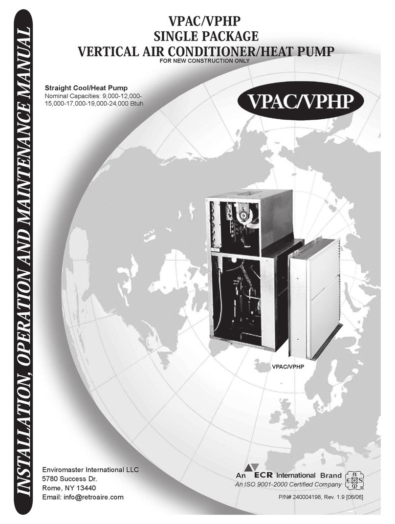
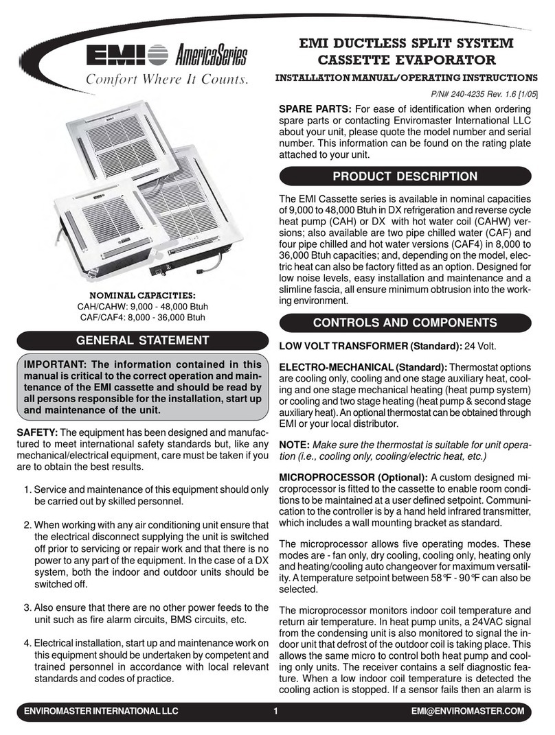
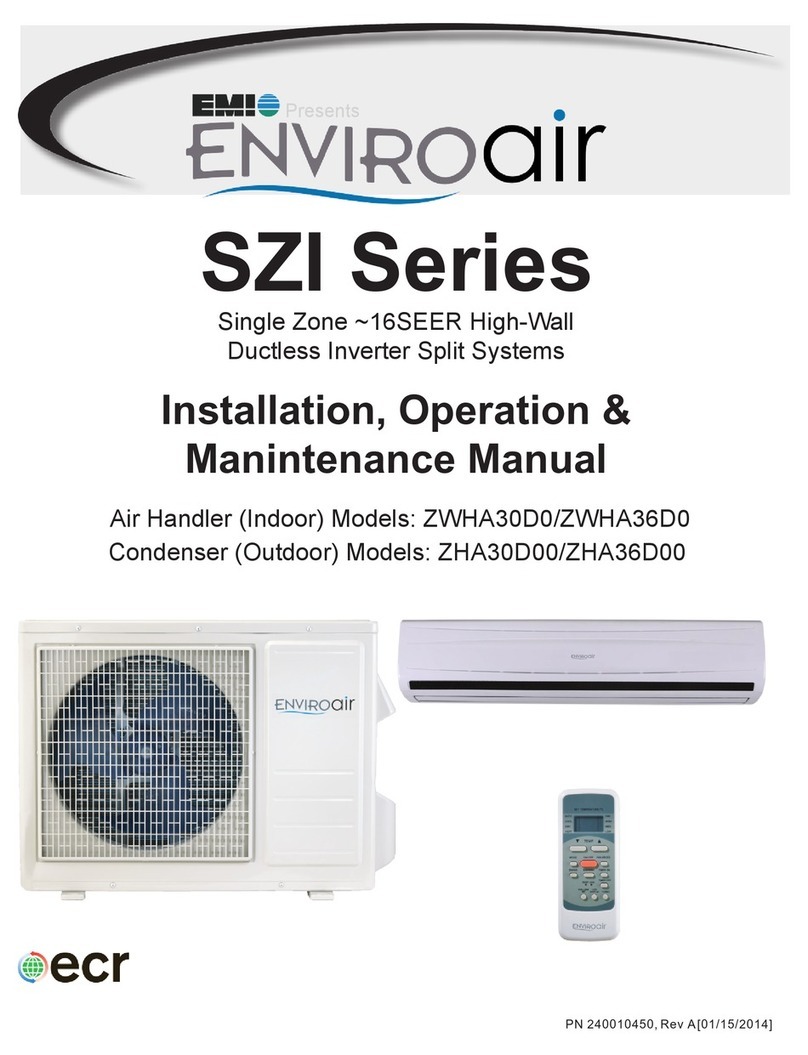
EMI VPAC30 User manual

1www.enviromaster.com/vpac
Enviromaster International, LLC
The VPAC/VPHP 30-36 offers an economic benefit
when used in a multi-room suite by supplying condi-
tioned air to more than one room without the need to
install another PTAC/PTHP. This is also a design ad-
vantage since the second room does not need an ex-
terior wall for a second unit.
The VPHP 30-36 heat pump is intended to be a lim-
itedrangeheatpump,whichmeansutilizingasupple-
mentedheatoptionisrecommendedsinceheatpump
operation will cease at approximately 40°F outdoor
temperature. Consult factory for availability of a full
range defrosting heat pump version.
Each system is supplied with a ready-to-install wall
sleeve and outdoor louver. The cabinet is constructed
with 20 gauge galvanized steel with a G-90U corro-
sion resistant rating and the insulated top discharge
evaporator compartment provides quiet ducted, con-
ditioned air delivery to other room location(s).
The VPAC/VPHP 30-36 is backed by EMI and ECR
International and is tested and rated in accordance
with ARI standard 390 and UL-1995. Due to ongoing
product development, product designs and specifica-
tions may change without notice. Please contact the
factory for more information.
CONDENSATE REMOVAL
TheVPAC/VPHP30-36requiresan internal drain sys-
tem due to its unique draw-thru condenser design.
Condenser side drain stub(s) are integral to the chas-
sis and are very easy to connect a drain hose to.
AIR SYSTEMS
Motors are thermally protected PSC type. Air stream
surfaces are insulated with 1/4 inch fiberglass or 1/8
inch volara. The evaporator fan is a forward curved
type directly mounted to the motor shaft. The con-
denser propeller utilizes a draw-thru design for im-
proved efficiency.
PRODUCT DESCRIPTION
The VPAC/VPHP 30-36 single package vertical air
conditioner (SPVAC) and heat pump (SPVHP) cre-
ates new options in layout and space utilization. The
VPAC/VPHP30-36offerslowcost operationand quiet,
comfortable air distribution, especially when used in
multi-room suites, apartments, healthcare facilities,
and homes.
Framed into a concealed closet enclosure for low op-
erating sound levels, the VPAC/VPHP 30-36’s verti-
cal discharge vent allows ducting to the top of the
room(s)forsuperior aircirculation anddistribution. Mul-
tipleair supply grilles can distribute air whenusedwith
a soffit and intake grilles can be located on the sides
of the enclosure.
The VPAC/VPHP 30-36 can be applied in a ducted
returnair application or can remain non-ducted asde-
livered. If ducted, the closet enclosure does not re-
quire minimum clearances other than what is recom-
mended for adequate service access. If non-ducted,
minimum clearance options must be adhered to as
dictatedforoptimalperformanceandsound. See note
on minimum clearance dimensions in the illustation
titled ”Exploded View Of Typical Installation” on page
2 of this document. (Figure 1)
VPAC/VPHP 30-36
INSTALLATION, OPERATION, AND MAINTENANCE MANUAL
Nominal Cooling Capacity: 30,000 - 36,000 Btuh
P/N 240-4554 Rev. 1.0 [03/04]
VPAC/VPHP 30-36 Single Package Vertical Air Conditioner
(SPVAC) and Heat Pump (SPVHP)

2Manufactured in Rome, NY, USA
VPAC/VPHP
! !
• Front mounted control box
• Manual fresh air damper
• Microprocessor control board
-Universal control board:canbe used instraight
cool electric, hydronic heat, or cooling/heat
pump applications.
- Fan purge: fan remains on for 60 seconds af-
ter heat/cool call is dropped (“auto” mode only)
- Anti-short cycle compressor protection
- Random start timer: prevents multiple units
from simultaneous start-ups (straight cool only)
- Freeze protection: prevents evaporator freeze
ups
-Low ambient lockout:preventscompressor op-
eration in cold outdoor temperatures.
- Test operation: all timers are eliminated to al-
lowease oftestingafterinstallation(straightcool
only)
- Compatible with fossil fuel, electric heat, mer-
cury or electronic thermostats
-Refrigerant hot gas bypass for operation in low
outdoor ambient conditions (cooling cycle only)
OPTIONAL CONTROLS AND COMPONENTS
• Supplemental electric heat
• 265/277V (contact factory for availability)
• Painted condenser louver
• Remote wall thermostat
• Return air access panel (w/disposable return air
filters)
ELECTRICAL WIRING
WARNING
Beforeaccessing the control compartment,discon-
nect power to the unit. Failure to do so could result
in serious injury or electrical shock.
All field wiring must be done in accordance to NEC
and local codes. Check the unit rating plate for circuit
ampacity and breaker(s) or fuse size(s). Use only
HACR type breakers or time delay fuses. Select the
proper wire for the ampacity rating. Some units re-
quire more than one power supply. Check the name-
plate and wiring diagram for further instructions.
IMPORTANT: The unit is wired for 230V primary
voltage from the factory. The transformer must be
rewiredby the installerifthe jobsite voltageis 208V.
Each vertical unit is equipped for a 24V wall thermo-
stat connection.
STANDARD CONTROLSAND COMPONENTS
• Cooling or heat pump chassis w/high efficiency
scroll or reciprocating type compressor
• Custom wall sleeve
• Anodized aluminum outdoor louver for field in-
stallation (optional colors available)
For designed performance, sound levels,
and service, maintain a minimum of 6” on
both sides and front for non-ducted return
air applications only.
Ducted return air applications only require
minimal spacing for service requirements.
Consult ECR Engineering if these mini-
mums can not be met. Depending on the
application and return air introduction,
some reconfiguration is likely to be accom-
modated.
ROUGH WALL SLEEVE OPENING
Unit Size Width Height
30 28 9/16" 32 3/8"
36 28 9/16" 36 1/4"
6”
6”
6”
FIGURE 1 - EXPLODED VIEW OF TYPICAL INSTALLATION

3www.enviromaster.com/vpac
Enviromaster International, LLC
! !
INSPECTION
Carefully check the shipment against the bill of lad-
ing. Make sure all chassis, wall sleeves, and louvers
(as well as any options) have been received. Inspect
each component for damage. The carrier must make
proper notation on the delivery receipt of all damage
identified and complete a carrier inspection report.
Concealed damage must be reported to the carrier
within 15 days of the receipt of the shipment.
IMPORTANT: The purchaser must notify the EMI
traffic department of all damage and is responsible
for filing any necessary claims with the carrier.
APPLICATION LIMITATIONS
The VPAC/VPHP 30-36 should be installed in
accordance with all national and local safety codes.
Minimumandmaximumoperationconditionsmustbe
observed to assure maximum system performance
with minimum service required. Refer to table below
for application limitations of the VPAC/VPHP 30-36.
CAUTION
Avoid possibility of electric shock and personal in-
jury. Disconnect all power before removing chas-
sis or performing any cleaning, servicing, or main-
tenance.
GENERALINSTALLATION
EnviromasterInternationalrecommendsinstallingthe
VPAC/VPHP 30-36 before any carpentry work is
startedfortheenclosure. It is very importantfor proper
air flow and sound levels that a minimum clearance of
6” between the enclosure and the chassis be main-
tained. It is also very important that the rough opening
in the wall for the wall sleeve and louver be the cor-
rect dimension and in the exact position necessary
for installation. (Figure 1)
The platform height should be the same level as the
bottom of the wall opening. Because wall sleeve
depths can vary depending on overall wall thickness,
it is critical that wall thickness be determined before
ordering the wall sleeve. (Figure 2) Consult factory
for available wall sleeve sizes.
1. Install 1/2” x 1/2” or 1” x 1” foam tape (supplied)
totheunitcondensertop and sides to seal against
the wall sleeve. (Figure 3)
FIGURE 3 - INSULATION & WEATHER ANGLES
Install supplied
1/2” x 1/2” foam
insulation along
top and sides of
condenser box.
(IMPORTANT:
Position as far
forward toward
outdoor side as
possible.)
Weather Angle
Position (One on
each side)
APPLICATION LIMITATIONS
Cool Heat
115 75
DB/WB DB DB/WB DB
Cool Heat Cool Heat
67/57 50 90/72 80
Minimum Maximum
Outdoor Ambient Air Temperature °F
Indoor Ambient Air Temperature °F
Cool
67
Minimum DB Maximum DB
Exterior Wall
Wall Sleeve
Assembly Cross Section
of Typical Wall
½” x ½” Foam Gasket
Overall Wall
Thickness
Wall Sleeve
Outdoor Louver
Drip edge will
extend outside
exterior wall
when installed
to guide con-
densate away
from building Lag Holes
(4 Per Side)
WallSleeveDepth = Overall Wall
Thickness- 1.25” (Louver Depth)
FIGURE 2 - DETERMINING WALL SLEEVE DEPTH
Interior Wall

4Manufactured in Rome, NY, USA
VPAC/VPHP
! !
!!
2. Attach the weather angles to the chassis using
the screws provided.
3.Slide chassis into wall sleeve, assuring that wall
sleeve studs on the wall sleeve flanges align with
the holes in the weather angles.
4. Attach left and right weather angles to wall
sleeve using the two 1/4-20 nuts provided.
5. Install plenum and duct work.
6. Plug in the supplied low voltage harness and
run it to the wall thermostat as shown in the unit’s
wire diagram.
CONDENSATE DRAIN
The VPAC/VPHP 30-36 is equipped with a 3/4” con-
denser side drain stub in the front of the base pan.
Because of the unit’s unique draw-thru condenser
design, this drain stub must be connected to an
internal condensate removal system.
INDOOR MOTOR SPEED TAP SELECTION
WARNING
Beforeaccessing the control compartment,discon-
nect power to the unit. Failure to do so could result
in serious injury or electrical shock.
For information on indoor motor speed tap selection,
please refer to the “VPAC/VPHP 30-36 Indoor Motor
Speed Tap Selection Chart” (Figure 4) and/or the la-
bel attached to the chassis of the unit.
The motor comes factory wired for the corresponding
units as described in the 230V column. Please make
speedtapchanges as requiredbyjob site voltage and/
orexternal staticpressure (e.s.p.) Speedtap changes
may need to be made from factory settings and Envi-
FIGURE 5 - RETURN AIRACCESS PANEL
NOTE: Available with solid doors if separate intake is used.
Access
Panel Frame
Frame
20” x 30”
Disposable
Filter
34”
60”
romaster International will not be liable for any sys-
tem problems that could arise if motor speed is not
changed to match application.
RETURN AIR ACCESS PANEL (WITH FILTER)
Return air access panels are unit capacity specific.
Be sure to specify unit capacity when placing an or-
der.
It is necessary to work closely with the other trades to
locatetheopeningforthereturnairaccesspanel.The
return air access panel must be installed with enough
room available to remove the unit if necessary. The
frame is installed with screws through the lag holes
into the frame studs and should be level and plum.
(Figure 5) The return air access panel is set onto the
frame and held in place with six screws.
FINAL INSPECTIONAND START UP
WARNING
Moving parts can cause injury so exercise caution
when testing the unit.
1. Hard wire line voltage power to unit. Refer to
unit rating plate for proper voltage and amperage/
fuse size.
NOTE: Some units may require two power sup-
plies (check nameplate and wiring diagram for fur-
ther instructions.)
FIGURE 4 - VPAC/VPHP 30-36 INDOOR MOTOR SPEED
TAP SELECTION CHART
Unit Size ESP 230V 208V 197V
0.1 Blu Blu Blu
0.2 Blu Blu Blk
0.3 Blu Blu Blk
0.1 Blk Blk Blk
0.2 Blk Blk Blk
0.3 Blk Blk Blk
Tap Key - Blu (Med), Blk (High)
30
36

5www.enviromaster.com/vpac
Enviromaster International, LLC
!!
2. Connect low voltage wiring from thermostat to
unit.
IMPORTANT: The outdoor air sheet metal splitter
baffle must be in the proper position to prevent re-
circulation.
3. Turn power on and check for proper operation.
HEATING: Set the wall thermostat to heat mode.
Set the thermostat above the room setting. Allow
some time for heat to come from the discharge
grilles. Do not operate unit when the panels are
removed.
COOLING: Set the wall thermostat to cool mode.
Setthe thermostatbelowtheroom temperatureset-
ting and allow time for cool air to come from the
discharge grilles. The thermostat can be set at the
most desired setting with the selector switch in the
heat or cool position.
4. Make sure that there is nothing to interfere with
the room discharge air or the return air.
WARNING
Do not operate unit without filter in place or use as
a temporary heating/cooling source during con-
struction.
MANUAL FRESH AIR DAMPER
The fresh air manual damper allows the user to move
freshairintothespacetobeconditioned.The damper
handle is located behind the evaporator coil. To ac-
cess, slide access door on service panel and slide
fresh air door to desired position.
SEQUENCE OF OPERATION
CHOOSING A THERMOSTAT
Enviromaster International offers a thermostat that is
compatiblewiththeVPAC/VPHP30-36.Thisisasingle
stage cool/heat, mercury bulb thermostat that can be
used in all Retroaire cooling, heating or heat pump
applications. The thermostat has an adjustable set-
point range of between 55°F and 95°F. There are two
independent, adjustable stops that can limit the heat-
ing or cooling range of the thermostat. A non-mer-
cury, electronic thermostat is available if needed.
Please contact the factory for more information.
SELECTINGA COMPATIBLE THERMOSTAT
When selecting a thermostat other than those offered
byEnviromaster International, itis importantto choose
a single stage heat/cool, 24V thermostat.
COOLING ONLY WITH ELECTRIC OR
HYDRONIC HEAT (VPAC ONLY)
Select a thermostat that is compatible with a cooling -
electric heat system. The thermostat should have “R”,
“Y”, “W” and “G” terminals.
HEAT PUMP WITH ELECTRIC HEAT
(VPHP ONLY)
Select a thermostat that is compatible with a cooling -
single stage heat - heat pump system. The thermo-
stat should have “R”, “Y”, “O” and “G” terminals.
Retroaire™ units are single stage heating only. The
electric heat and heat pump will not operate simulta-
neously.
FAN OPERATION
Some thermostats are equipped with an auto/on fan
switch. When this switch is placed in the on position
the indoor fan will run continuous. When the switch is
in the auto position the indoor fan will cycle with the
call for heating or cooling.
FAN PURGE (AUTO MODE ONLY)
Aftertheroomthermostathasbeen satisfied,the purge
feature allows the indoor fan to remain on for an addi-
tional 60 seconds. This increases efficiency by pulling
the remaining energy from the unit.
COOLING OPERATION
After connecting the thermostat to the unit place the
system switch in cool mode.Adjust the set-point tem-
perature below the room temperature. The compres-
sor and fan motors will start and cooling will begin.
Place the set-point temperature above the room tem-
perature.The compressor and condenserfanwillstop
andthe indoor fan will remain on for anadditionalsixty
seconds.
IMPORTANT: The start of the compressor will not
take place until the anti-short/random start time
period has elapsed.

6Manufactured in Rome, NY, USA
VPAC/VPHP
!!
EMERGENCY HEAT (VPHP ONLY)
WARNING
Beforeaccessing the control compartment,discon-
nect power to the unit. Failure to do so could result
in serious injury or electrical shock.
Shouldthe heatpumpsystem fail,itis possible toforce
the control board into electric heat mode. This is a
temporary solution until the heat pump system can be
repaired. Locate the circuit board in the control sec-
tion of the unit. Locate the terminals where the out-
doorsensorconnectstothecircuitboard.Usinga small
needle nose type pliers, disconnect one side of the
sensor from the circuit board. This will appear to the
circuit board as an outdoor coil freeze condition,
thereby energizing the electric resistance heater on
the call for heat.
ANTI-SHORT CYCLE TIMER RANDOM START
Thisfeature will prevent compressor short cycling and
also prevent multiple units in a single facility from si-
multaneously starting following a power outage. This
delay on break feature ensures that the compressor
remainsoffbetween cycles until the three-minutetime
delay period has elapsed, allowing system pressures
to equalize before restarting.
The random start feature, initiated after a power fail-
ure,will add a random time delay(between5-120sec-
onds) to the three-minute anti short cycle time follow-
ing a power outage. This will stagger the starting of
multiple units in a single facility allowing a building to
slowly go back on line when power is restored.
INDOOR COIL FREEZE PROTECTION
This feature will prevent the indoor coil from freeze up
in the cooling mode. Indoor coil freeze up can occur
due to a dirty air filter, low refrigerant charge or low
room or outdoor temperatures.This in turn can cause
compressor damage. Should a freeze condition be
detected, the compressor and condenser fan will be
switched off for a minimum of three minutes and until
the freeze condition is satisfied. During this time the
indoor fan will continue to run to aid in the defrost
process.
ELECTRIC HEAT OPERATION
Placethe thermostatsystem switch in heat mode.Ad-
just the set-point temperature above the room tem-
perature.Theelectricheatwillenergizealongwiththe
indoor fan motor. Heating will continue so long as the
set-pointremains aboveroom temperature.Nextplace
the set-point temperature below room temperature.
The electric heater will switch off and the indoor fan
will remain on for an additional 60 seconds.
HEAT PUMP COOLING OPERATION
(VPHP ONLY)
Cooling operation in a heat pump unit is described in
“Cooling Operation” above. The unit is equipped with
a reversing valve that is energized for cooling and de-
energized in heating mode.
HEAT PUMP HEATING OPERATION
(VPHP ONLY)
Heat pump units are “Limited Range” equipped with
back-up electric resistance heat. Limited range heat
pumps are designed to operate when outdoor tem-
peraturesare between75°Fand 40°Fandwith amaxi-
mum indoor temperature of 80°F. When the outdoor
temperature falls below approximately 40°F the unit
will switch from heat pump to electric resistance heat.
Electric heat will then remain as the heat source until
the outdoor temperatures rise above 50°F. The VPHP
30-36 is a single-stage heating unit. The electric heat
and heat pump will not operate simultaneously.
To operate the unit in heating mode, it must first be
connected to an appropriate heat pump thermostat.
(See “Choosing A Thermostat”). Select heat on the
thermostat system switch. Then, adjust the set-point
temperature above the room temperature. The com-
pressor and fan motors will start and heating will be-
gin.If the outdoor temperature is below approximately
40°F the heat pump system will not operate. Electric
heat will then take over the heating demand. Heating
will continue so long as the set-point temperature re-
mains above the room temperature. Place the set-
point temperature below the room temperature. The
heating mode will cease and the indoor fan will re-
main on for an additional sixty seconds.
IMPORTANT: The start of the compressor will not
take place until the anti-short/random start time
period has elapsed.

7www.enviromaster.com/vpac
Enviromaster International, LLC
!!
!!
MAINTENANCE
WARNING
Beforeaccessing the control compartment,discon-
nect power to the unit. Failure to do so could result
in serious injury or electrical shock.
The VPAC/VPHP 30-36 is designed and constructed
forreliabilityand longlife minimalmaintenance. Sched-
uled maintenance inspections should be performed 4
times a year. At the beginning of the cooling season,
a complete mechanical cooling check should be per-
formed and periodic minor inspections may be nec-
essary during the cooling season to adjust for varia-
tions in climate. At the beginning of the heating sea-
son, a complete mechanical heating check should be
performedand, again, periodic minor inspections may
be necessary to adjust for climatic changes.
WARNING
It is illegal to discharge refrigerant into the atmo-
sphere.Use proper reclaiming methods and equip-
ment when repairing this unit. Service should be
performed by a qualified service agency.
1. Disconnect power to the unit.
2. Remove the access panel and do a visual check
of the equipment. Look for obvious changes in the
unitsuchasdamaged coilsor evidenceofextended
wearon any movingparts.Checkfor unusual odors
or leaks (ex: burnt motor windings, water, or refrig-
erant) and make sure the base pan is clean.
3. Regular cleaning of the filter is required. Allow-
ing dust to collect on the filter will cause the unit to
lose efficiency and eventually malfunction. Check
filter once a month.
4.Inspect all electrical connections for frayed wires
andpoor connections.Terminalendsthat are loose
will eventually fail, causing a loss of performance
or worse.
5.Check fan motors and blower assemblies. Some
units may require a drop of light oil to motors and/
or bearing assemblies. Check setscrews and mo-
tormounting hardware,making suretheseare tight.
6. Centrifugal fan blades and blower cage assem-
bliesmustbeclean tooperate efficiently.Brushand/
or vacuum as necessary.
7. Inspect both indoor and outdoor coils. Use a fin
comb to straighten out any damaged fins. These
coils must be clean for proper operation.
IMPORTANT: Do not use a solvent-based cleaner
for this as some solvents produce a noxious odor
when you start the fan or electric heat.
8. Look for oil leaks or stains on or around the coil
and refrigerant lines. The presence of oil here indi-
cates a potentially serious problem (such as a re-
frigerant leak).
9.Inspect and clean the drainpanand drainline(s).
A good idea here is to use an anti-fungicide tablet
to keep the condensate system free from bacterial
contaminants.
10. Check seal around the unit.
IMPORTANT:Air leaks may make the conditioned
area uncomfortably drafty or produce noises.
Visually inspect the foam gasket between the wall
andtheunit,especially takingnoteofthe separation
between the air inlet for the condenser and the
condenser coil discharge. These two areas must
be sealed off from each other. If you experience
poor cooling operation or erratic operation, check
for air recirculation at the condenser coil.
11. Replace panel and reconnect the electrical
power.
TROUBLESHOOTING
NO HEAT OR COOLING
Checkto seeifthe unithaspower and ifthe thermostat
is satisfied. If the thermostat is not satisfied, call your
installing contractor or service contractor.

8Manufactured in Rome, NY, USA
VPAC/VPHP
SPECIFICATIONS AND PERFORMANCE
IMPORTANT: Due to ongoing product development, designs, specifications, and performance are subject to change without notice. Please consult
the factory for further information.
Enviromaster International LLC
5780 Success Dr., Rome, NY 13440
Phone: 1-800-228-9364
Fax: 1-800-232-9364
VPAC/VPHP 30-36 Performance Data
.10 .20 .30
VPAC30 30,000 0.68 9.2 9.7 N/A N/A 1,050 990 930
VPAC36 36,000 0.70 9.8 10.0 N/A N/A 1,350 1,290 1,210
VPHP30 29,800 0.73 8.7 9.7 27,600 2.4 1,050 990 930
VPHP36 35,600 0.74 9.0 9.7 33,500 2.7 1,350 1,290 1,210
SEER Heat
Pump COP External Static
Model Cooling
Btu Sensible
Heat EER
A52" A56"
B28" B28"
C24 1/2" C28"
D20" D20"
E2 1/4" E4"
F5/8" F5/8"
G8" G8"
H 16" H 16"
J3/4" J3/4"
K7 1/4" K9"
L10" L10"
M11" M10 1/4"
N22" N17 3/4"
Dimension
Model
30 36
VPAC 30-36 COOLING ONLY ELECTRICAL SPECIFICATIONS
Model Total Min Max HACR
Number Amps HP RLA LRA Amps HP Amps Voltage Breaker
30 208/230/60/1 1.7 0.25 14 73 3 0.5 18.7 197 22.3 35
36 208/230/60/1 1.7 0.25 16.3 88 3 0.5 21 197 25.1 40
VOLTS/HZ/PH M.C.A.
Condenser Fan Compressor Evap Fan
VPHP 30-36 HEAT PUMP ELECTRICAL SPECIFICATIONS
Model Total Min Max HACR
Number Amps HP RLA LRA Amps HP Amps Voltage Breaker
30 208/230/60/1 1.7 0.25 14 73 3 0.5 18.7 197 22.3 35
36 208/230/60/1 1.7 0.25 16.3 100 3 0.5 21 197 25.1 40
Evap Fan M.C.A.VOLTS/HZ/PH Condenser Fan Compressor
Total MCA Max Brkr Total MCA Max Brkr
208 4089 19.7 22.7 28.4 35 * - - -
230 5000 21.7 24.7 31.0 35 * - - -
208 6134 29.5 32.5 40.7 45 - - -
230 7500 32.6 35.6 44.5 45 - - -
208 8178 39.3 42.3 52.9 55 - - -
230 10000 43.5 46.5 58.1 60 - - -
208 12268 59.0 22.7 28.4 40 * 42.3 52.9 55
230 15000 65.2 24.7 31.0 40 * 46.5 58.1 60
5
7.5
Heater No.
* VP-30 Requires 35 amp breakerfor compressor circuit
*VP-36 Requires 40 amp breaker forcompressor (circuit#1)
10
15 (VPAC36
only)
Voltage Watts HT.
Amps
VPAC/HP 30-36 ELECTRIC HEAT SPECIFICATIONS
Circuit #1 Circuit #2
A
C
M
B
D
E
F
G
H
K
L
J
N
Supply Air
Return Air
Outdoor
Air Exhaust
Outdoor
Air Intake
This manual suits for next models
3
Table of contents
Other EMI Air Conditioner manuals

EMI
EMI enviroair szi ZWHA User manual

EMI
EMI enviroair 9000 Btu Instruction manual

EMI
EMI S1CG User manual

EMI
EMI MC2 Series s User manual

EMI
EMI VPAC Instruction manual

EMI
EMI WLHG09 User manual

EMI
EMI AmericaSeries LLC-09 User manual

EMI
EMI E Verter WLHV09 User manual

EMI
EMI S1CV User manual

EMI
EMI CAHG09 User manual
Popular Air Conditioner manuals by other brands

Mitsubishi Electric
Mitsubishi Electric MSZ-GE71VA operating instructions

Fujitsu
Fujitsu AST18AB operating manual

Carrier
Carrier 40VMM007A 3 Series Installation and maintenance instructions

Mitsubishi Electric
Mitsubishi Electric CITY MULTI PEFY-P30NMAU-E5 Operation manual

HOFFEN
HOFFEN LL04-18JR instruction manual

Frigidaire
Frigidaire FFRA0511R1 use & care