EMI E Verter WLHV09 User manual

P/N# 240009097, Rev. D [08/07/2013]
WLHV
Variable Speed Ductless Split System
High- Wall Air Handlers
WLHV09 WLHV12 WLHV18 WLHV24 WLHV30 WLHV36
9,000 12,000 18,000 24,000 29,800 33,400 COOL
2.6 3.5 5.3 7.0 8.7 9.8 kW
8,800 10,000 18,000 21,000 26,000 26,400
2.6 2.9 5.3 6.2 7.6 7.7 kW
Installation, Operation and
Maintenance Manual
ECR International, Inc.
2201 Dwyer Avenue,
Utica NY 13501
web site: www.ecrinternational.com

2
.................................................................................................................. 3
........................................................................................................ 4
............................................................................................................ 5
......................................................................................................... 6
............................................................................................................................. 8
........................................................................................................................ 9
.................................................................................................................12
.........................................................................................................................13
.......................................................................................................................17
..................................................................................................................18
...........................................................................................................................20
.........................................................................................................................21
......................................................................................................................22
.................................................................................................................23
....................................................................................................26
.......................................................................................................30
.....................................................................................................................31
...........................................................................................................32
..............................................................................................................................33
..........................................................................................................................34
.........................................................................................................36
.....................................................................................................37
.................................................................................................................38
.................................................................................................40
TABLE OF CONTENTS
Information and specications outlined in this manual in effect at the
time of printing of this manual. Manufacturer reserves the right to
discontinue, change specications or system design at any time without
notice and without incurring any obligation, whatsoever.
Check our website frequently for updates: www.enviromaster.com

3
Shipping damage MUST be reported to the carrier IMMEDIATELY.
Examine exterior.
Remove cover and examine compressor and piping for signs of damage.
RECEIVING INFORMATION
General Information

4
IMPORTANT SAFETY INFORMATION
Become Familiar With Symbols
Identifying Potential Hazards.
Safety Information
DANGER
!
WARNING
!
CAUTION
!
NOTICE
WARNING
!
WARNING
!

5
DIMENSIONAL/PHYSICAL DATA
Figure 1 - Dimensions and Shipping Weight
AC
B
D
E
[38mm]
1 1/2”
[133.35mm]
5 1/4”
[51mm]
2”
[311mm]
12 1/4”
[111.13mm]
4 3/8”
[185.74mm]
7 5/16”
Model
A B C D E Shipping
weight
Depth in
(mm)
Height in
(mm)
Length in
(mm)
Mounting
bracket
clearance
in (mm)
Tubing access
clearance
in (mm)
Pounds
(kg)

6
GENERAL PRODUCT INFORMATION
Product Description
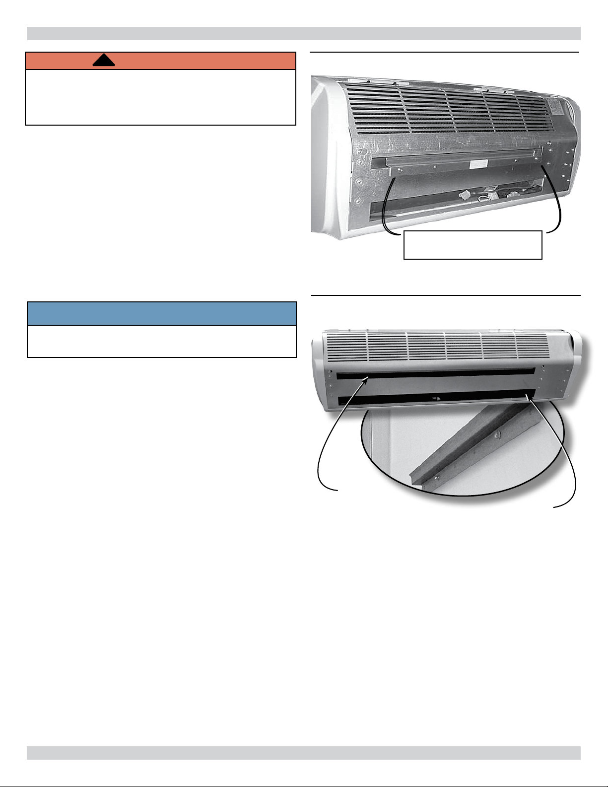
Controls And Components
(Factory-Installed Or Supplied)
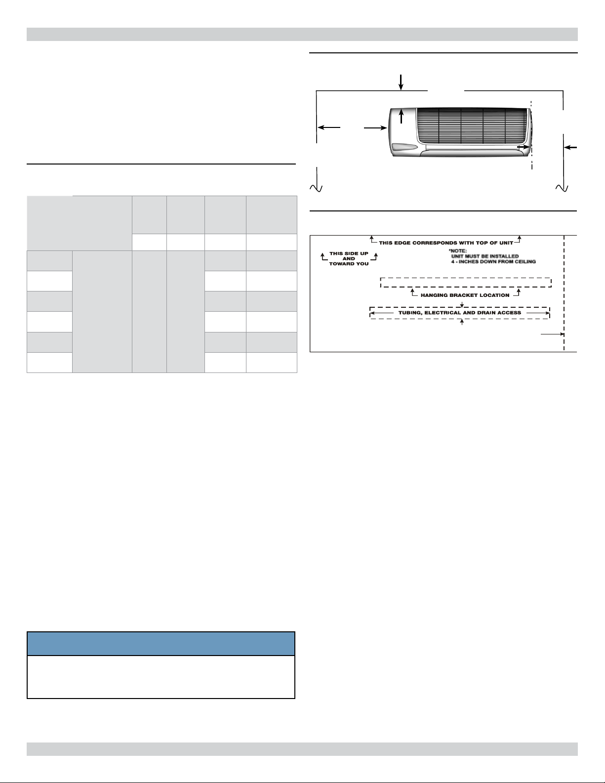
Cabinet Features:
Optional Equipment
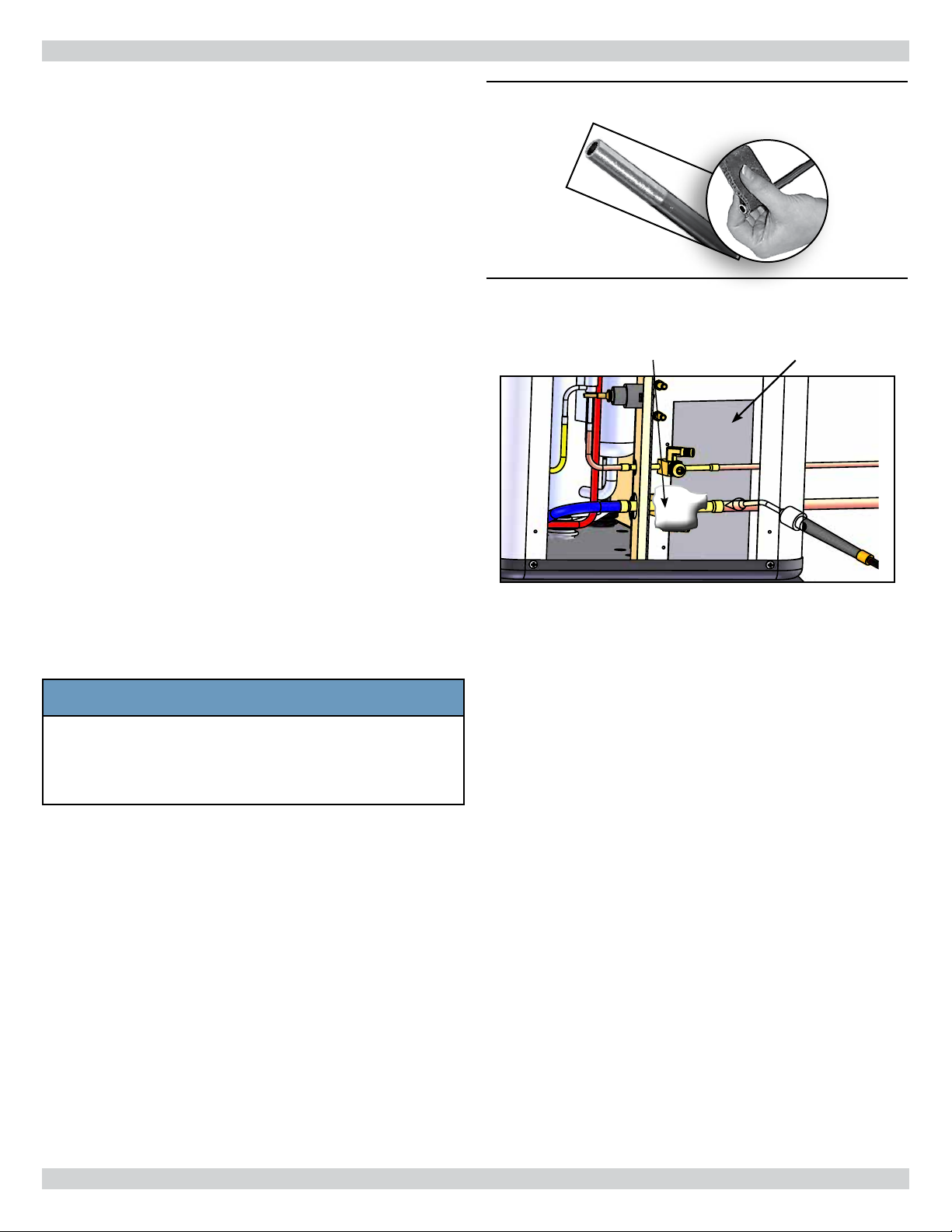
Installer Supplied Items
Both tubes need
to be insulated.

7
GENERAL PRODUCT INFORMATION
Ceiling
wall
wall
4” Minimum
10”
Minimum
6”
Min.
Figure 2 Minimum Service Clearances
Figure 3 Mounting Template
S1CV/
S1HV
or
Model
Max.
Length
Equivalent
Feet
Max.
Lift
Max.
Trap
Height
Liquid
Line
Suction
Line
“H” “P” O.D. O.D.
09
1/4" 1/2"
12 1/4" 1/2"
18 3/8" 5/8" *
24 3/8" 5/8" *
30 3/8" 3/4"
36 3/8" 3/4"
.
Site Preparation
NOTICE
Installation Considerations
Table 1 - Tubing Specications - Both Tubes
Insulated

8
UNIT MOUNTING
WARNING
!
Unit Mounting Considerations
1.
.
2.
3.
.
4.
5.
.
Figure 4 - Wall Hanging Bracket
Figure 5 Removing Front Grill
NOTICE
Mounting
slot
Slot for piping

9
REFRIGERANT PIPING
Figure 6 - Remove Bottom Panel
Piping Preparation
.
See .
Figure 7 - Piping Connections
Suction line
(When a reducing bushing is required, install
only here, at the indoor suction-line connection.)
Liquid line
Condensate drain

10
REFRIGERANT PIPING
Wet rag heat sink Shield
Line Sizing
1.
.
2.
Refrigerant Piping
1.
2.
3.
4.
5.
6.
7.
8.
Figure 8 - Clean Ends Of Tubing
Figure 9 - Place Wet Rag “Heat Sink" Over
Valves Plus A Sheet Metal Shield To
Protect Paint
NOTICE

11
REFRIGERANT PROCESSING
Refrigerant Processing
1.
2.
A.
B.
C.
D.
3.
Refer to refrigerant charge table for specied charge.
4.
Only add/remove R410A in liquid
form. See .
Charge with dial-a-charge or weighed in with scale.
NOTICE
Common Suction Port
• Common Suction Port
COMMON
DISCHARGE
PORT
HIGH PRESSURE
SWITCH
COMMON
SUCTION
PORT
Figure 10 - Common Suction, Common
Discharge, & High Pressure Switch

12
REFRIGERANT PROCESSING
Condenser Wall Unit
Pairing
Line Charge
Per Foot
Factory
Charge
Table 2 - S1CV / S1HV R410A Refrigerant
Charge Table

13
ELECTRICAL WIRING
Site Preparation For Wiring
WARNING
!
1.
2.
3.
4.
.
5.
6.
.
Connect Wiring
.
High Voltage Electrical Wiring
1.
See .
2.
3.
Low Voltage Electrical Wiring
Figure 14 - Before Removing End Cap
Figure 15 - Removing End Cap
Figure 16 - Rotate Louver Down To Expose
Screw
Control box Remove screw
Figure 17 - Electrical Connection

14
ELECTRICAL WIRING
Cooling Only Connection
.
Heat Pump Connection
.
18 AWG.
Figure 18 Wiring Connections
Low Voltage
Connections
Ground
L1
L2
Figure 19 - Unit-Mounted Controls —
Cooling Only
Figure 20 - Unit-Mounted Controls —
Heat Pump Connection

15
ELECTRICAL WIRING
Optional Wired Wall Mounted Thermostat
Connection
Heat Pump Applications
Heat pumps only:
Finishing
Figure 21 - Low Voltage Box
Control Box Replace Screw

16
ELECTRICAL WIRING
Figure 22 - Wall-Mounted Thermostat Conguration — Cooling Only
Figure 23 - Wall-Mounted Thermostat Conguration — Heat Pump

17
CABINET ASSEMBLY
Assemble Cabinet
Assemble Cabinet
1.
2.
3.
4.
5.
6.
7.
8.
Figure 24 - Replace Bottom Panel
1 2
3
Figure 25 - Replace Left End Cap
4 5
6
Figure 26 - Replace Grille
7
8

18
S1CV / S1HV Condenser Operation
S1CV / S1HV Sequence of Operation
CONDENSER OPERATION

19
CONDENSER OPERATION

20
Controller Operation
.
.
Wired Wall Control Operation
Before Starting The Unit
1.
2.
3.
4.
5.
6.
7.
.
8.
9.
10.
11.
INITIAL START-UP
This manual suits for next models
5
Table of contents
Other EMI Air Conditioner manuals

EMI
EMI MC2 Series s User manual

EMI
EMI FCP/FHP User manual

EMI
EMI AmericaSeries LLC-09 User manual

EMI
EMI S1CA9000 User manual

EMI
EMI CAHG09 User manual

EMI
EMI enviroair szi ZWHA User manual

EMI
EMI S1C User manual

EMI
EMI enviroair 9000 Btu Instruction manual

EMI
EMI ENVIROair SZI Series Owner's manual

EMI
EMI WLHG09 User manual