Eminent LFT XII User manual

EMINENT
TECHNOLOGY
INCORPORATED
LFT XII
CENTER CHANNEL LOUDSPEAKER
REFERENCE MANUAL
Eminent Technology, Inc. 225 East Palmer Street Tallahassee, Florida 32301
Phone: (850) 575-5655 FAX: (850) 224-5999 Email: info@eminent-tech.com
Website:www.eminent-tech.com

2
TABLE OF CONTENTS
THE LFT-12 PLANAR MAGNETIC CENTER CHANNEL LOUDSPEAKER....... 3
ABOUT THE LFT-12............................................................................................... 3
UNPACKING........................................................................................................... 3
SETTING UP THE LFT-12...................................................................................... 3
MOUNTING INSTRUCTIONS............................................................................... 3
AMPLIFIER REQUIREMENTS AND SENSITIVITY .......................................... 4
GETTING THE BEST PERFORMANCE FROM THE LFT-12............................. 4
CLEANING.............................................................................................................. 4
A REVIEW OF PREVIOUS LOUDSPEAKER TECHNOLOGY .............................. 5
THE ELECTROSTATIC LOUDSPEAKER............................................................... 5
THE TRADITIONAL PLANAR MAGNETIC LOUDSPEAKER………………….6
THE RIBBON LOUDSPEAKER …………………………………………………....7
EVALUATING EARLIER APPROACHES.................................................................. 8
LINEAR FIELD TRANSDUCER CONSTRUCTION............................................. 9
DIAPHRAGM CONSTRUCTION ........................................................................... 9
THE MAGNET / FRAME STRUCTURE ................................................................ 9
TECHNICAL INFORMATION.................................................................................... 11
FREQUENCY RESPONSE..................................................................................... 12
IMPEDANCE CURVE............................................................................................ 12
CROSSOVER INFORMATION............................................................................. 13
WARRANTY................................................................................................................... 14
WARRANTY FORM ..................................................................................................... 15

3
THE LFT-12 PLANAR MAGNETIC CENTER CHANNEL LOUDSPEAKER
Congratulations on your purchase of the Eminent Technology LFT-12! The LFT-12 is the
most advanced planar magnetic loudspeaker technology available. With proper care and use, the
LFT-12 will last many years. To get the most out of your LFT-12, please read this manual carefully.
Do not forget to fill out the warranty form in the back of the manual and send it in to us for
registration of your purchase.
ABOUT THE LFT-12
This loudspeaker is not for every application because of its limited maximum sound pressure
level and low to moderate sensitivity. When using this loudspeaker, these limitations should be
carefully considered. The loudspeaker is designed to operate in rooms of less than 3500 cubic feet.
This is a rough estimate as there are many variables that would affect this figure. Operated full range,
the loudspeaker is intended for use at low to moderate (95dB SPL maximum) sound pressure levels.
The maximum recommended SPL is 103 dB at 1 meter.
UNPACKING
The shipping box contains a Manual (this document), and the LFT-12 Center Channel
Loudspeaker wrapped in bubble wrap. Be careful when lifting the loudspeaker from the carton, it
weighs approximately 20 pounds.
SETTING UP THE LFT-12
The LFT-12 is magnetically shielded and is intended for use in a home theater setting. It can be
placed on top or below a television, or it can be wall-mounted. Typically, the optimum distance
between the LFT-12 and the rear wall is 1 to 5 feet in an average room. The overall tonal balance and
image presentation of the loudspeaker is affected by how it is aimed at the listener. The on-axis
frequency response of the LFT-12 is essentially flat, and it is often best to position the loudspeaker so
that the main listening position is on axis with the loudspeaker. For optimum sound quality, the
loudspeaker should be no more than 7 feet from the listening position.
MOUNTING INSTRUCTIONS
For best performance, mount the LFT-12 on a shelf above or below the video screen. This
mounting position will best anchor dialog to the screen and give the best three-dimensional acoustic
projection. In some cases, where the screen is a large tube or projection television, the loudspeaker
can be mounted on top of the television and angled toward the listening position using the pointed feet
installed in the base of the loudspeaker. The loudspeaker is magnetically shielded and should have
little interference on the picture quality.
Most mounting schemes will place the LFT-12 in an area where the wall behind the
loudspeaker is acoustically reflective. To get the best tonal balance from the loudspeaker, we suggest
experimenting with sound absorbent material on the wall behind the loudspeaker. Open cell foam and
carpet are good choices as sound absorbers.
Wall mounting is also possible for the LFT-12. Although the bass response will be best when
the loudspeaker is separated from the wall by at least one foot, good performance can be achieved
with less space between the mounting wall and the LFT-12. When wall mounting we suggest
attaching metal brackets or wall mount loudspeaker stands. Any hinge or wall attachment method
should be capable of handling the loudspeaker’s weight, 20 pounds, with a good safety margin. We
again recommend experimenting with sound absorbent material on the wall behind the loudspeaker

4
AMPLIFIER REQUIREMENTS AND SENSITIVITY
Almost any audio amplifier can be used with the LFT-12. The minimum recommended
amplifier power rating is 35 watts RMS per channel for moderate listening levels. Amplifiers up to
150 watts per channel can be used but this much power could over drive the speaker in the full range
mode. The amplifier should be capable of driving a four-ohm load. Through a narrow part of the
speaker’s low frequency range the impedance dips to around 4 ohms. This does not pose a problem
for most solid state or tube amplifiers that are rated to drive a four-ohm load. Tube type power
amplifiers can usually use the 8-ohm tap.
The speaker’s sensitivity is low by traditional speaker measurements. Depending on the
measurement method, it will measure as low as 80dB. The directional characteristics of the speaker
make the apparent efficiency slightly higher, but it will still be less efficient than a conventional
loudspeaker. A 100-watt audio amplifier can drive a speaker about 20dB above its sensitivity rating.
For the LFT-12, this means 100-104dB at 1 meter. When the amplifier output is 100 watts per
channel, the speaker’s maximum sound output limit can quite possibly be exceeded. The diaphragm
“slapping” against the magnets indicates this over-excursion.
GETTING THE BEST PERFORMANCE FROM THE LFT-12
The LFT-12 is designed to have flat on-axis frequency response. This may present a problem
with some program material at lower volume levels, depending on your listening tastes. At low sound
levels, the human ear is mostly sensitive to midrange frequencies and high frequencies, to a lesser
degree. Because of this, the speaker may sound thin at low volume levels.
The LFT-12 is purposely designed to be highly directional. This characteristic improves
three-dimensional acoustic images by focusing the sound into a tight radiation pattern. The speaker
should point directly toward the listener. If the frequency balance is too bright, when the speakers are
aimed directly toward the listening position, use the adjustment spikes to raise or lower the speaker’s
axis of projection. If positioned correctly, the LFT-12 can project apparent sound sources well beyond
the boundaries of the speaker, if the program material contains the correct information.
All drivers in an audio system should ideally operate in phase. Careful consideration should
be paid to the correct polarity of all loudspeakers. The LFT-12's positive terminal with a positive
signal applied will displace the diaphragm toward the front of the speaker. The LFT-12 is a dipole;
meaning sound radiated from the back of the speaker is the same as what comes from the front of the
speaker
The LFT-12’s panels have accurate phase and impulse response. This means there is no time
delay between low and high frequencies electronically entering and acoustically leaving the speaker.
In the LFT-12, if a low and high frequency signal appear at the input to the speaker at the same time-
they will (as sound) leave the speaker at the same time. In a cone speaker, this is usually the case only
over a very narrow range of frequencies. This presents problems when interfacing speakers with
unique crossover design and type. Some crossovers are phase inverting through the crossover
frequency; some are not.
CLEANING
The wood cabinet surface of the speaker can be cleaned with ordinary household wood cleaners.
Do Not spray any liquids on the speaker that would get on the diaphragm. Dust can be removed from
the speaker with a feather duster, damp cloth or by brushing the surface of the speaker with a clean
paintbrush. Dust can be removed fromm the grille with a brush or feather duster.

5
TECHNICAL DESCRIPTION
The Eminent Technology Linear Field Transducer (LFT) is a full-range, push-
pull, dynamic planar loudspeaker. In a sense, it is the magnetic equivalent of a
push-pull electrostatic loudspeaker, differing in that it requires no step-up
transformer or bias voltage, and that the audio signal is applied directly to its
diaphragm.
THE LFT-12
A REVIEW OF PREVIOUS LOUDSPEAKER TECHNOLOGY
To fully understand the strengths of the LFT design, one must first consider the
design and operation of this speaker's three most notable antecedents: the push-pull
electrostatic loudspeaker (ESL); the traditional, single-ended planar magnetic
loudspeaker, and the ribbon loudspeaker.
THE ELECTROSTATIC LOUDSPEAKER
The electrostatic loudspeaker is constructed with a very thin (half mil or less) diaphragm
made of Mylar or a similar material, to which a light coating of mildly conductive substance such as
graphite has been applied. This diaphragm is suspended on a rigid frame and sandwiched between
two stationary conductive grids (usually perforated metal plates) called stators.
FRAME
REAR STATOR
RESISTOR
TRANSFORMER +
--
TO
AMPLIFIER
TO BIAS
VOLTAGE
SUPPLY
[PERFORATED
METAL PLATE]
FRONT
STATOR
CONDUCTIVE
DIAPHRAM
ELECTROSTATIC LOUDSPEAKER
[TOP VIEW CROSS SECTION]

6
A DC charge of high voltage (in the thousands of volts) but very low current, known as the
bias voltage, is applied to the conductive diaphragm and kept constant. A step-up transformer is
introduced to increase the usable voltage of the amplifier's output (while simultaneously decreasing
the current), and the two ends of the transformer's output coil are connected to the two stators.
As the amplifier produces a continuously varying AC voltage, (the amplified music signal),
the charge on the two stators will also continuously change in synchronization with the music; and
since the two stators are connected to two different ends of the transformer's output, one stator will
take on a predominantly negative charge at the same time and to the same extent that the other stator
takes on a predominantly positive charge. The constant-charge diaphragm will thus undergo a
continuously changing state of attraction to and repulsion from the two stators as their polarization
changes, and it is this motion that excites the air to the front and rear of the speaker and produces
sound.
THE TRADITIONAL PLANAR MAGNETIC LOUDSPEAKER
The traditional planar magnetic also starts with a thin Mylar diaphragm, one side of which is coated
with adhesive and fitted with an aluminum wire voice grid, (analogous to the voice coil of a
conventional cone driver). The diaphragm is held taut in a metal frame. On the front of this frame is a
large sheet of perforated metal, to which rows of vertically aligned strip magnets have been fastened.
+
-
TO AMPLIFIER
FRAME
DIAPHRAM
VOICE GRID
[ACTUALLY A
CONTINUIOS LOOP]
PERMANENT
STRIP
MAGNETS
PERFORATED
METAL
SHEET
N
S
S
S
N
SINGLE-ENDED PLANAR MAGNETIC
[TOP VIEW CROSS-SECTION]
Spacing exaggerated to show detail
From there, the operation of a single-ended planar magnetic loudspeaker is remarkably
similar to that of a conventional cone driver: The amplifier's output is sent directly through the voice
grid and, because it is suspended within a stationary magnetic field, the grid moves back and forth
within that field in synchronization with the AC voltage that is the amplified music signal. Since the
voice grid is permanently fastened to a taut diaphragm, the diaphragm also moves in synchronization
with the music signal, exciting the air and producing sound.

7
THE RIBBON LOUDSPEAKER
The third and final antecedent to consider is the ribbon loudspeaker: a distinctly different sort
of transducer, but one that is similar (in principle, at least) to the single-ended planar magnetic
loudspeaker. The ribbon’s primary distinction is that its “diaphragm” and “voice element” are one
and the same. A ribbon driver is based on a long, narrow strip of conductive material; in practice, thus
far, all true ribbons have used a strip of very thin corrugated aluminum for this purpose. The two ends
of this strip are electrically connected to the amplifier’s output, and are physically anchored such that
the strip is suspended within a stationary magnetic field--with magnets positioned at the edges of the
strip.
PERMANENT MAGNET
PERMANENT MAGNET
ALUMINUM
RIBBON
ELEMENT
N
S
_
+
TO AMPLIFIER
[LEADS CONNECTED TO
TOP AND BOTTOM OF
RIBBON ELEMENT]
RIBBON DRIVER
[TOP VIEW CROSS-SECTION]
The operating principle is straightforward from there: the amplifier’s output passes directly
through the aluminum strip--which, because it is suspended within a permanent magnetic field, moves
back and forth in synchronization with the signal, producing sound.

8
EVALUATING EARLIER APPROACHES
Not surprisingly, each of the approaches described above has its own unique set of pros and
cons. The electrostatic, because its diaphragm is so thin and light, offers exceptionally good transient
response and reproduction of subtle, low-level musical detail. And, because it is a true push-pull
device (i.e., its diaphragm is, by design, driven from both the front and the rear), the ESL operates in a
linear fashion. Typically, gross distortion results only when the driving amplifier clips into the
speaker, or when, in an attempt to play the speaker louder than its design allows, its step-up
transformer reaches a point of saturation.
On the negative side of the ledger, the ESL does require passing the amplified musical signal
through a transformer, which can introduce its own colorations and non-linearities. Also, some ESLs
are prone to a condition known as arcing: Under the conditions of stress induced by playing an ESL
loudly, it is not uncommon for an electrical spark to jump between one stator and the diaphragm (a
phenomenon exactly analogous to lightning), burning a minute hole in the diaphragm and, over time,
causing failure.
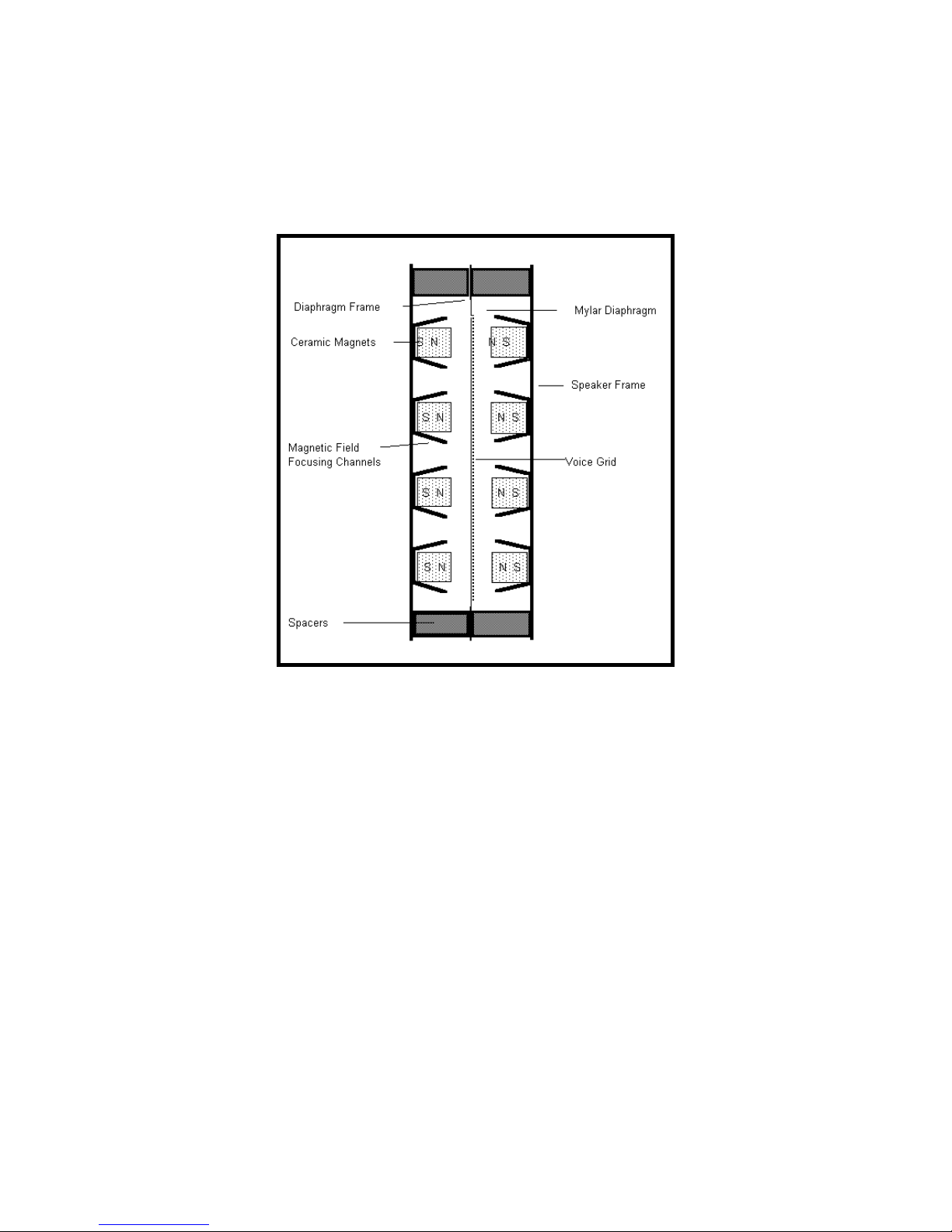
As for the planar magnetic, its strengths are similar to those of the ESL--although the addition
of several feet of wire and an adhesive coat make for a somewhat more massive diaphragm, limiting
this design’s transient capabilities by comparison. However, the planar magnetic requires no step-up
transformer or bias voltage supply, and it has the added benefit of being an extremely manageable
load for most amplifiers. However, the most specific drawback of the traditional planar magnetic is
that it is a single-ended (as opposed to push-pull) device: As the diaphragm’s physical excursion
increases, the voice grid moves further away from its optimal location within the permanent magnetic
field (at least in one direction). Thus, at the very instant when this speaker is called upon to reproduce
large-amplitude waveforms, it is least able to do so without distortion.
In many ways, a ribbon driver can be an excellent performer: the moving element (the
“ribbon” itself) is extremely light, allowing good “speed” and transient performance as well as
freedom from coloration. There is no significant physical structure on either side of the ribbon’s
radiating pattern. The ribbon’s main problem is not one of performance but of application: it cannot
be used to reproduce low frequencies. To create a moving element large enough to generate
frequencies lower than a few hundred Hz would mean moving opposing magnetic poles so far apart
that they would no longer exert a sufficient magnetic field over the entire area of the ribbon.
Also, when a ribbon is operated at frequencies approaching the element’s own resonant
frequency (which is naturally quite low, due to its high compliance), the ribbon element stretches and
“bows” to a point where it is no longer within the magnetic gap. To get around either of these
problems means to move the permanent magnet structure from the edges of the element to one entire
side of the element, and/or to bond the element to a “host” diaphragm, such as a sheet of Mylar, and to
clamp that diaphragm around its perimeter. In either case the driver is no longer a ribbon; it is, in fact,
a planar magnetic. To date, no one has succeeded in creating a full range ribbon loudspeaker.

9
LINEAR FIELD TRANSDUCER CONSTRUCTION
Eminent Technology’s Linear Field Transducer, introduced as the LFT, represents a new
approach to the design and construction of a high-quality loudspeaker*. It builds on the strengths of
the above designs while eliminating many of their drawbacks.
DIAPHRAGM CONSTRUCTION
The construction of the LFT-12 diaphragm begins by laminating a very thin sheet of
aluminum foil to a half-mil-thick sheet of Mylar. A voice grid pattern, created by means of CAD
(Computer-Aided Design) technology, is silk-screened onto the foil side; the remainder of the
aluminum--the part not covered by ink from silk-screening is chemically etched away, in a manner
similar to the etching of traces on a printed-circuit board. The ink is then washed away, leaving a
voice grid of near perfect uniformity. This technique results in a diaphragm/voice coil grid that is still
less than two mils in total thickness, and also permits relatively narrow spaces between the individual
traces, so the diaphragm can be evenly driven over its entire surface.
With this construction, the entire diaphragm area of the LFT-12 is driven full range. For
midrange and high frequencies, the wavelength of sound is smaller than the diaphragm, making the
speaker very directional. This characteristic substantially improves performance for separation and
three-dimensional effects over speakers that use conventional cone drivers.
THE MAGNET / FRAME STRUCTURE
The magnet/frame structure developed for the LFT-12 is also unique. Eminent Technology
builds its magnets onto a steel plate and a series of channels. The magnets and steel channels have a
size and shape that have been carefully designed to help shorten the magnetic flux path and
concentrate the strength of the magnetic field on the appropriate area of the diaphragm/voice grid.
Two U.S. patents (4,837,838 and 5,901,235) have been granted to Eminent Technology on its
innovative magnetic circuits for flat panel loudspeakers.
Interestingly, one of the biggest challenges faced in creating a true push-pull dynamic speaker
was not a design consideration but rather a matter of construction difficulty: to assemble a rigid
structure with very powerful permanent magnets at the front and the rear, both sides opposing each
other with tremendous force. ***Warning*** This speaker should never be taken apart as it will
destroy itself upon removal of the hardware holding it together. Please consult the factory for
any service needs.
By applying such new techniques to planar loudspeaker construction, Eminent Technology
has been able to eliminate many of the flaws inherent in earlier designs and significantly reduce the
size.
Cloth is used on the back of the speaker to resistively load the diaphragm. This lowers the Q
of the diaphragm’s free air resonance. The planar-magnetic panels, which are derived from the LFT-
10 speaker, have a redesigned magnet structure, taking advantage of new Neodymium magnets to
increase efficiency.
The use of a welded channel and steel plate frame dispenses with the need for perforated
sheet metal (an “off-the-shelf” material presumably used for reasons of economy and ease of
manufacture.) thus greatly improving dispersion, especially at high frequencies.
Since it is now possible to have a powerful, precisely aligned magnet structure on both sides
of the diaphragm, true push-pull operation has been achieved: Regardless of the degree of excursion

10
the diaphragm undergoes, the voice element is always optimally positioned within the magnetic field.
The result is extremely linear performance throughout the audible range, with a profound increase in
dynamic range and an absolute minimum of distortion.
LFT-12 LINEAR FIELD TRANSDUCER
[TOP VIEW CROSS SECTION]

11
TECHNICAL INFORMATION
GENERAL SPECIFICATIONS
Frequency Response 70Hz -20Khz + or -4dB
Sensitivity 85dB@ 1 watt/1 meter
Minimum suggested power 35 watts RMS per channel into 8 ohms
Maximum suggested power 150 watts per channel into 8 ohms
Maximum sound pressure level 103 dB at 1 meter (midband)
Total Radiating Area 140 sq. in.
Impedance 8 ohms nominal (4.2 ohms minimum)
Dimensions 26”W by 5.5” D by 10.5” H
Weight 19.5 lbs.
Available Finishes Oak, Walnut, Black Painted Oak
Manufacturer’s Suggested Retail Price $950.00
LFT-12 PANEL SPECIFICATIONS
Magnet Type Ceramic 8, Neodymium 40
Foil Thickness .0007 in.
Mylar Thickness .0005 in.
Laminate Adhesive Thickness .00015
Gap Between Conductors .030 in.
Peak-to-Peak Diaphragm Excursion .120 in.
Diaphragm Weight 1 gram
Free Air Resonance 120 Hz

12
FREQUENCY RESPONSE
MEASUREMENTS TAKEN WITH AN INPUT OF 1W/1METER
IMPEDANCE CURVE

13
CROSSOVER INFORMATION
LFT-12 ELECTRICAL SCHEMATIC

14
WARRANTY
Thank you for purchasing the LFT-12. Eminent Technology Inc. warrants the LFT-12
Loudspeaker to be free from defects in materials and workmanship for a period of 30
days from the date of purchase. Within that period, any failure of the LFT-12 will be
corrected without charge for parts, labor, or transportation from the factory. After this
period, pending receipt of the warranty form (filled out and mailed to Eminent
Technology, and postmarked no later than one month after the date of purchase), the
above warranty will be extended to five years for parts and three years for labor. This
warranty is transferable to subsequent owners, pending notification from the original
owner, in writing, within 10 days of the personal sale.
The obligation of Eminent Technology under the terms of this warranty does not extend to:
1. Any LFT-12 installed or operated without regard for the instructions contained in this
manual.
2. Any LFT-12 while under performance testing or after being used in such a test, by any
personnel or facility not authorized by Eminent Technology.
3. Any other component or part connected to or operated in conjunction with the LFT-12.
4. Any traumatic, accidental damage, or damage incurred in shipping, or defects which
upon examination by Eminent Technology and in its sole opinion have been caused by
abuse, neglect, improper or abnormal installation, or operation for extended periods in
industrial applications.
This warranty is not applicable if any part of the LFT-12 has been removed or taken
apart, repaired, altered, or modified by anyone, nor if the serial numbers have been
defaced or rendered illegible.
If an Eminent Technology product is removed from the country in which the original
consumer purchase was made, Eminent Technology dealers and distributors in other
countries are not obligated by the terms of this warranty. Eminent Technology reserves
the right to incorporate design refinements and changes to its products without notice or
obligation. If practical, such design modifications will be made available to owners of
existing units for a reasonable charge.
Under the terms of this warranty, Eminent Technology expressly does not insure for loss
of use of the LFT-12 due to failure or periods of repair. Warranty repairs can only be
carried out by the factory. The LFT-12 must be returned prepaid in its original factory
carton to:
Eminent Technology, Inc
225 East Palmer Street
Tallahassee, FL 32301
Phone: (850) 575-5655
FAX: (850) 224-5999
service@eminent-tech.com

15
EMINENT TECHNOLOGY, INC. LFT-12
WARRANTY FORM
Name _______________________________________________________
Address______________________________________________________
City_________________________________________________________
State_______________________ Zip_________________________
Dealer Purchased From_________________________________________
Dealer Address________________________________________________
City_________________________________________________________
State_______________________ Zip_________________________
Date Purchased_______________ Serial Number ________________
Please complete this form and return to:
EMINENT TECHNOLOGY
225 East Palmer Street
Tallahassee, FL 32301
U.S.A.
Table of contents
Other Eminent Speakers manuals

Eminent
Eminent LFT-6 User manual

Eminent
Eminent LFT-3 User manual

Eminent
Eminent LFT-8b User manual

Eminent
Eminent LFT-8b Use and care manual

Eminent
Eminent Ewent EW3516 User manual

Eminent
Eminent LFT-11 User manual

Eminent
Eminent LFT-VIII User manual

Eminent
Eminent Ewent EW3516 Instructions for use

Eminent
Eminent ewent EW3515 User manual

Eminent
Eminent LFT XVI User manual