Eminent LFT XVI User manual

EMINENT
TECHNOLOGY
INCORPORATED
LFT XVI
HYBRID LINEAR FIELD TRANSDUCER LOUDSPEAKER
REFERENCE MANUAL
Revised:
12/28/05
Eminent Tec nology, Inc. 225 East Palmer Street Talla assee, Florida 32301
P one:
(850) 575-5655
FAX:
(850) 224-5999
Email:
info@eminent-tech.com
Website:
.eminent-tech.com

Strong magnetic fields are present
at and around t is loudspeaker.
Devices t at are adversely affected
by ig levels of magnetic flux,
suc as television sets and
pacemakers, s ould be kept at
least t ree feet away from eac
speaker. Also, keep in mind w en
any ferrous objects are broug t
close to t e speakers. Hold steel
tools securely w en setting up and
adjusting t e LFT-XVI, to prevent
a ex key or screwdriver from
slipping from your and and
damaging t e Mylar diap ragm.
2
ATTENTION:
STRONG
MAGNETIC
FIELDS
_____________

TABLE OF CONTENTS
Installation of t e LFT-16 ........................................................... 5
Unpacking the Speakers ............................................................. 5
Speaker Assembly ...................................................................... 5
Positioning the Speakers in the Listening Room ....................... 5
Imaging ...................................................................................... 6
The T eeter Level Control ........................................................ 6
Amplifier Requirements ............................................................. 6
Bi-Wiring and Bi-Amping ......................................................... 7
Bi-Amping .................................................................................. 7
Tec nical Description .................................................................. 8
Electrostatic Loudspeakers ......................................................... 8
Planar Magnetic Loudspeakers .................................................. 9
Ribbon Loudspeakers ............................................................... 10
Evaluating Earlier Approac es ................................................ 11
Electrostatics ............................................................................ 11
Planar Magnetics ...................................................................... 12
Ribbons .................................................................................... 12
T e Linear Field Transducer .................................................... 12
Diaphragm Construction .......................................................... 13
The Magnet/Frame Structure ................................................... 13
Panel Frequencies ..................................................................... 15
General Specifications ............................................................... 15
LFT-16 Impedance Curves ........................................................ 16
LFT-16 Impedance Data ............................................................ 17
Crossover Information ............................................................... 17
Frequency Response ................................................................... 18
LFT-16 Mid-Range Panel Specifications ................................ 19
Mid-Range Panel Design ........................................................... 20
LFT-16 Woofer Specifications .................................................. 20
Additional Woofer Specifications ............................................. 22
Woofer Design ............................................................................ 22
Woofer Enclosure ....................................................................... 23
3

Warranty ..................................................................................... 24
4

A complete technical description of the LFT-16 is included in this
manual and begins on page 7. It is recommended that you become
familiar with this information because an understanding of the LFT
principals will assist you in the proper set up of these loudspeakers.
The LFT-16 is shipped in one box. The box contains the two hybrid linear field
transducer loudspeakers. Remove the padding from the top and remove the grill
cloth frames, which are wrapped in cardboard. Then remove one speaker
separately from the box. Be careful not to put too much pressure on the woofer
cone when lifting the speaker out of the box. After removing the speaker from its
box place on the carpet or a soft surface.
Do not attempt to remove or loosen hardware on the drivers themselves.
The magnets are held together under great force and personal injury could
result.
There are two-assembly requirement for both speakers. To attach the grill cloth
frames, place the additional Velcro fasteners to the corners of each speaker.
Then snap the grill cloth into place. Second, adjust the setscrews at the bottom
of the speaker. Use a 3/32 allen hex wrench to adjust the desired height.
Do not attempt to remove setscrews for the bottom of each speaker.
Speaker placement is critical for correct imaging, frequency balance, low
frequency performance, and efficiency.
The LFT-16 speakers are a mirror imaged pair and should be set up with the
tweeter panels to the inside. Ideally the base of the speaker should be above the
floor 2 feet or more. The use of a speaker stand is recommended. Wall mounting
is suitable for home theater use.
Low frequency performance in particular can be determined by the shape of the
room and the speaker's distance from the wall immediately behind them.
Typically, the optimal distance between the LFT’s and the rear wall is 1 to 5 feet
in an average room.
The overall frequency balance of the LFT-16 is somewhat affected by the degree
to which the speakers are toed in toward the central listening position. The on-
axis frequency response of the LFT-16 is essentially flat, and it is often best to
Installation of
the LFT-16
Unpacking the
Speakers
Speaker
Assembly
Positioning
the Speakers
in the
Listening
Room
5

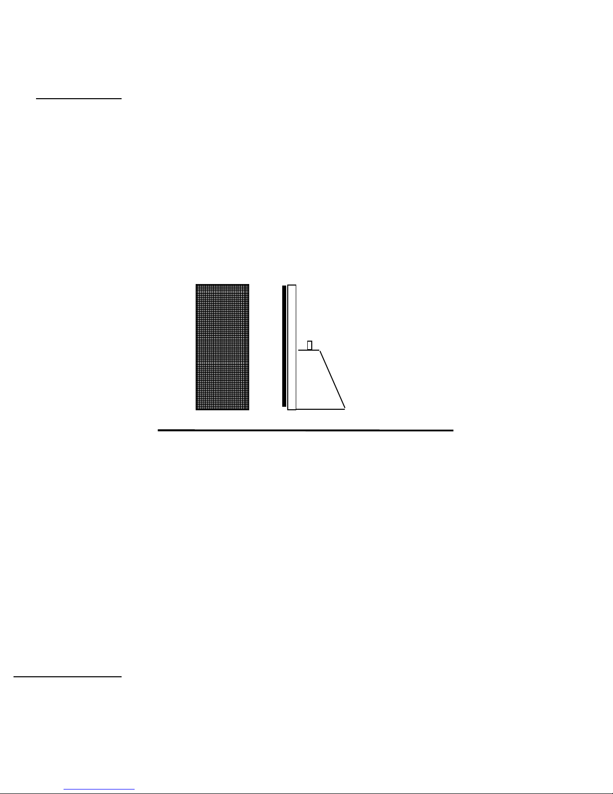
position the speakers so that the main listening position is about
on axis with each speaker. Slight mid-range frequency balance
changes can be obtained by pointing the speakers slightly away
from the listening position. Adjusting the speakers’ degree of
vertical tilt with the pointed feet can also alter this balance.
Overall imaging depends primarily on the distance separating the
two speakers relative to their distance from the preferred listening
position; it is also affected by the degree of toe-in. We cannot
accurately predict what will work best in your listening room, and
can suggest only that you begin with the drawing on the previous
page as a starting point or general guideline. Keep in mind that
the parameters that affect frequency balance also tend to affect
imaging properties, and vice versa, so it is best to adjust speaker
placement in small increments and to note carefully all of the
changes effected by each shift in position before proceeding
further.
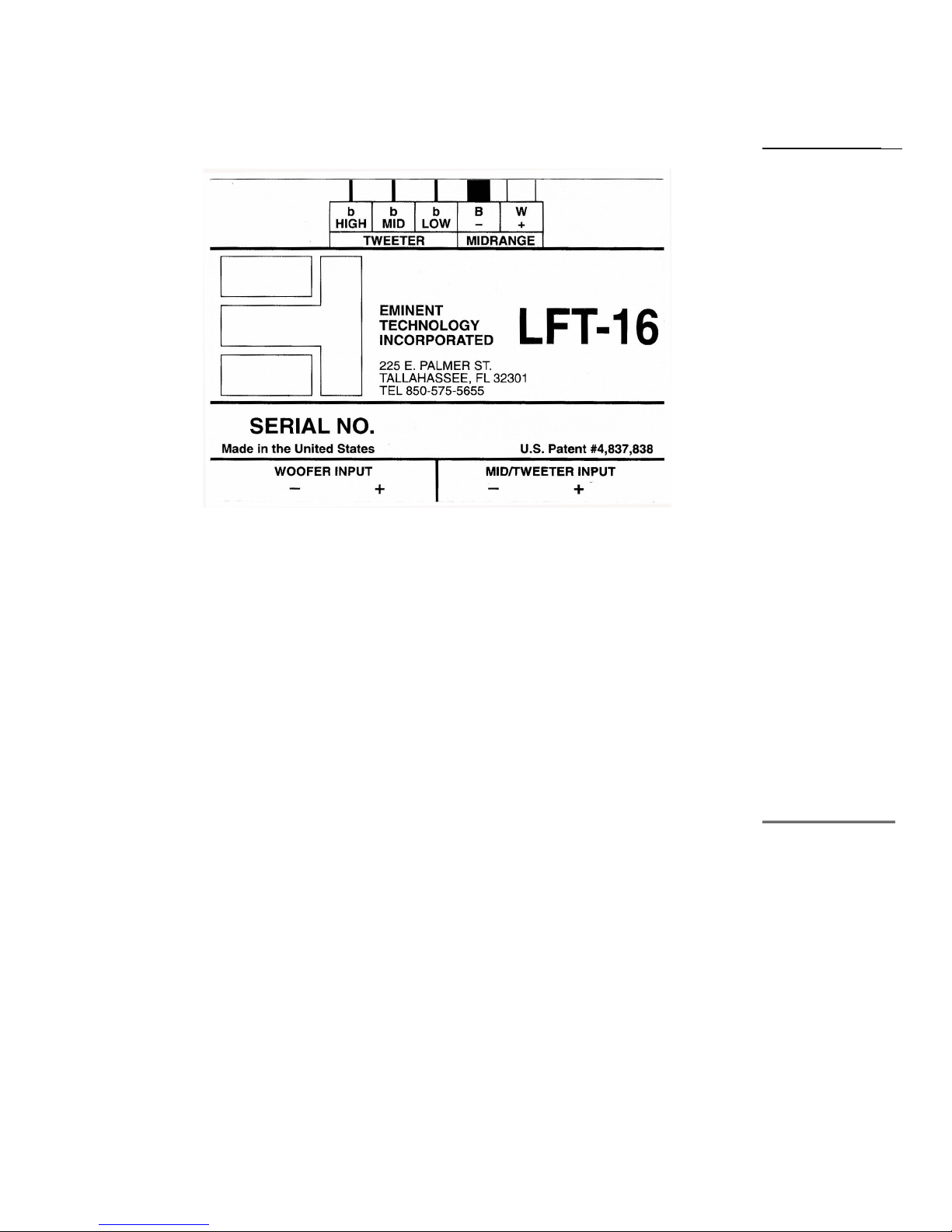
The high frequency performance of the LFT-16 is adjusted with
the tweeter level control. There are three tweeter level positions:
High, Mid and Low. These levels adjust the tweeter output in
approximately 3 dB increments. It is best to start with the tweeter
level setting in the middle position. Adjust the speakers for the
best overall frequency balance and then decide if more or less
high frequency energy is needed.
The LFT-16 is wired for 8-ohm operation and is appropriate for
use with most moderately powered tube and solid-state amplifiers.
The efficiency is 85dB with a 2.83-volt drive (1 “8” ohm watt).
The efficiency rating is lower than average. However, the LFT-
16 radiates a planar wave front, and as such, on axis its apparent
efficiency at the listening position is higher than the numerical
rating implies. The LFT-16 has a minimum rating of 25 watts per
side, tube or solid state. It can handle “music power” levels (short
term burst) of 200 watts or more with out difficulty. The largest
recommended amplifier size for the LFT-16 is 200 watts.
The LFT-16 does not require a high current amplifier. A receiver
may be used if it has sufficient power. Tube amplifiers should be
used with the 8-ohm tap.
Imaging
The Tweeter
Level Control
Amplifier
Requirements
6

The LFT-XVI is configured to allow bi-wiring or bi-amping with a
minimum of trouble.
Bi-wiring simply means connecting a single stereo amplifier (or two
mono amps) to a pair of speakers by using two pairs of speaker cables.
Connect the hot and ground conductors of a pair of cables to the same
output terminals on one channel of the amplifier; the other ends are
connected to the separate woofer and mid/tweeter inputs of the LFT-16
(All speaker cables should be the same length). The effects of bi-
wiring tend to be subtle; the slight improvement may be worth the
relatively modest cost of an extra pair or speaker cables. Bi-wiring also
permits experimenting with different types of cables for the two inputs;
you may find that one type is best suited for bass performance, while
another works best on the mid/treble side.
Bi-amping requires and additional stereo amplifier or pair of mono
amps. You will also need some means of insuring that only the desired
portion of the frequency range reaches each amplifier. The simplest
way to accomplish this is with an external electronic crossover;
however, this can also be done by hard-wiring low-pass and high-pass
filters into the inputs of the bass/mid and treble amplifiers, respectively.
For the low/ frequency amp, a 180Hz low-pass filter (6 dB/octave) is
required; for the mid/treble amp, a 180Hz. high-pass filter (also 6
dB/octave) is required. If you wish to pursue this method, your dealer
or the manufacturer of your amplifiers should be able to help you
determine the specific parts necessary. Note that you will also need a
level control on either one of the stereo amps or on the crossover,
regardless of which approach you take to bi-amping. Contact Eminent
Technology or refer to the schematic in the back of this manual to
modify the crossover for proper speaker operation.
Bi-Wiring and Bi-
Amping
Bi-Amping
7

The Eminent Technology Linear Field
Transducer is a full-range, push-pull, dynamic
planar loudspeaker. In a sense, it is the
magnetic equivalent of a push-pull electrostatic
loudspeaker, differing in that it requires no
step-up transformer or bias voltage, and that
the audio signal is applied directly to its
diaphragm.
The LFT-XVI
To fully understand the strengths of the LFT design, one must
first consider the design and operation of this speaker's three most
notable antecedents: the push-pull electrostatic loudspeaker
(ESL); the traditional, single-ended planar magnetic loudspeaker,
and the ribbon loudspeaker.
The electrostatic starts with a very thin (half mil or less)
diaphragm made of Mylar or a similar material, to which a light
coating of mildly conductive substance such as graphite has been
applied. This diaphragm is suspended on a rigid frame and
Technical
Description
Electrostatic
Loudspeakers
8

sandwiched between two stationary conductive grids (usually
perforated metal plates) called stators.
FRAME
REAR STATOR
RESISTOR
TRANSFORMER
+
--
TO
AMPLIFIER
TO BIAS
VOLTAGE
SUPPLY
[PERFORATED
METAL PLATE]
FRONT
STATOR
CONDUCTIVE
DIAPHRAM
PUSH-PULL ELECTROSTATIC
[TOP VIEW CROSS-SECTION]
Spacin exa erated to show detail
A DC charge of high voltage (in the thousands of volts) but very
low current, known as the bias voltage, is applied to the
conductive diaphragm and kept constant. A step-up transformer
is introduced to increase the usable voltage of the amplifier's
output (while simultaneously decreasing the current), and the two
ends of the transformer's output coil are connected to the two
stators.
As the amplifier produces a continuously varying AC voltage,
(the amplified music signal), the charge on the two stators will
also continuously change in synchronization with the music; and
since the two stators are connected to two different ends of the
transformer's output, one stator will take on a predominantly
negative charge at the same time and to the same extent that the
other stator takes on a predominantly positive charge. The
constant-charge diaphragm will thus undergo a continuously
changing state of attraction to and repulsion from the two stators
as their polarization changes, and it is this motion that excites
the air to the front and rear of the speaker and produces
sound.
The traditional planar magnetic also starts with a thin Mylar
diaphragm, one side of which is coated with adhesive and
fitted with an aluminum wire voice grid, (analogous to the
Planar Magnetic
Loudspeakers
9

voice coil of a conventional cone driver). The diaphragm is held
taut in a metal frame. On the front of this frame is a large sheet of
perforated metal, to which rows of vertically aligned strip
magnets have been fastened.
+
-
TO AMPLIFIER
FRAME
DIAPHRAM
VOICE GRID
[ACTUALLY A
CONTINUIOS LOOP]
PERMANENT
STRIP
MAGNETS
PERFORATED
METAL
SHEET
N
S
S
S
N
SINGLE-ENDED PLANAR MAGNETIC
[T OP VIEW CROSS-SECT ION]
Spacin exa erated to show detail
From there, the operation of a single-ended planar magnetic
loudspeaker is remarkably similar to that of a conventional cone
driver: The amplifier's output is sent directly through the voice
grid and, because it is suspended within a stationary magnetic
field, the grid moves back and forth within that field in
synchronization with the AC voltage that is the amplified music
signal. Since the voice grid is permanently fastened to a taut
diaphragm, the diaphragm also moves in synchronization with the
music signal, exciting the air and producing sound.
The third and final antecedent to consider is the ribbon: a
distinctly different sort of transducer, but one that is similar (in
principle, at least) to the single-ended planar magnetic. The
ribbon’s primary distinction is that its “diaphragm” and “voice
element” are one and the same.
Ribbon
Loudspeakers
10

A ribbon driver is based on a long, narrow strip of conductive
material; in practice, thus far, all true ribbons have used a strip of
very thin corrugated aluminum for this purpose. The two ends of
this strip are electrically connected to the amplifier’s output, and
are physically anchored such that the strip is suspended within a
stationary magnetic field--with said magnets positioned at the
edges of the strip.
PERMANENT MAGNET
PERMANENT MAGNET
ALUMINUM
RIBBON
ELEMENT
N
S
_
+
TO AMPLIFIER
[LEADS CONNECTED TO
TOP AND BOTTOM OF
RIBBON ELEMENT]
RIBBON DRIVER
[TOP VIEW CROSS-SECTION]
The operating principle is straightforward from there: the
amplifier’s output passes directly through the aluminum strip--
which, because it is suspended within a permanent magnetic field,
moves back and forth in synchronization with the signal,
producing sound.
Not surprisingly, each of the approaches described above has
its own unique set of pros and cons. The electrostatic,
because its diaphragm is so thin and light, offers
exceptionally good transient response and reproduction of
subtle, low-level musical detail. And, because it is a true
push-pull device (i.e., its diaphragm is, by design, driven
from both the front and the rear), the ESL operates in a linear
fashion. Typically, gross distortion results only when the
driving amplifier clips into the speaker, or when, in an attempt to play the
speaker louder than its design allows, its step-up transformer reaches a
point of saturation.
On the negative side of the ledger, the ESL does require passing the
amplified musical signal through a transformer, which can introduce its
Evaluating
Earlier
Approaches
Electrostatics
11

own colorations and non-linearities. Also, some ESLs are prone to a
condition known as arcing: Under the conditions of stress induced by
playing an ESL loudly, it is not uncommon for an electrical spark to jump
between one stator and the diaphragm (a phenomenon exactly analogous
to lightning), burning a minute hole in the diaphragm and, over time,
ruining it.
As for the planar magnetic, its strengths are similar to those of the ESL--
although the addition of several feet of wire and an adhesive coat make
for a somewhat more massive diaphragm, limiting this design’s transient
capabilities by comparison. But the planar magnetic requires no step-up
transformer or bias voltage supply, and it has the added benefit of being
an extremely manageable load for most amplifiers. However, the most
specific drawback of the traditional planar magnetic is that it is a single-
ended (as opposed to push-pull) device: As the diaphragm’s physical
excursion increases, the voice grid moves further away from its optimal
location within the permanent magnetic field (at least in one direction).
Thus, at the very instant when this speaker is called upon to reproduce
large-amplitude waveforms, it is least able to do so without distortion.
In many ways, a ribbon driver can be an excellent performer: the moving
element (the “ribbon” itself) is extremely light, allowing good “speed”
and transient performance as well as freedom from coloration. And there
is no significant physical structure on either side of the ribbon’s radiating
pattern. The ribbon’s main problem is not one of performance but of
application: it cannot be used to reproduce low frequencies. To create a
moving element large enough to generate frequencies lower than a few
hundred Hz would mean moving opposing magnetic poles so far apart
that they would no longer exert a sufficient magnetic field over the entire
area of the ribbon.
Also, when a ribbon is operated at frequencies approaching the element’s
own resonant frequency (which is naturally quite low, due to its high
compliance), the ribbon element stretches and “bows” to a point where it
is no longer within the magnetic gap. To get around either of these
problems means to move the permanent magnet structure from the edges
of the element to one entire side of the element, and/or to bond the
element to a “host” diaphragm, such as a sheet of Mylar, and to clamp
that diaphragm around its perimeter. In either case the driver is no longer
a ribbon; it is, in fact, a planar magnetic. To date, no one has succeeded
in creating a full range ribbon loudspeaker.
Eminent Technology’s Linear Field Transducer, introduced
as the LFT, represents a new approach to the design and
Planar
Magnetics
Ribbons
The Linear
Field
Transducer 12

construction of a high-quality loudspeaker*. It builds on the
strengths of the above designs while eliminating many of their
drawbacks.
The construction of the LFT-16 begins by laminating a very thin
sheet of aluminum foil to a half-mil-thick sheet of Mylar. A voice
grid pattern, created by means of CAD (Computer-Aided Design)
technology, is silk-screened onto the foil side; the remainder of
the aluminum--the part not covered by ink from the silk-screening
is chemically etched away, in a manner similar to the etching of
traces on a printed-circuit board. The ink is then washed away,
leaving a voice grid of near-perfect uniformity. This technique
results in a diaphragm/voice coil grid that is still less than one mil
in total thickness, and also permits relatively narrow spaces
between the individual traces, so the diaphragm can be
evenly driven over its entire surface.
The magnet/frame structure developed for the LFT-16 is also
unique. Eminent Technology builds its strip magnets into
individual steel channels, the size and shape of which have
been carefully designed to help “focus” the magnetic flux
lines and concentrate the strength of the magnetic field on the
appropriate area of the diaphragm/voice grid. These
channels are then welded to steel crossbars, which in turn are
bolted to the frame that holds the diaphragm in place.
Interestingly, one of the biggest challenges faced in creating a true
push-pull dynamic speaker was not a design consideration but
rather a matter of construction difficulty: to assemble a perfectly
rigid structure with very powerful permanent magnets at the front
and the rear, both sides opposing each other with tremendous
force. It was not until Eminent Technology developed a special
method for this assembly procedure that the Linear Field
Transducer became a reality.
* The design and construction of the LFT is patented.
Diaphragm
Construction
The
Magnet/Frame
Structure
13

By applying such new techniques to planar loudspeaker
construction, Eminent Technology has been able to eliminate
many of the flaws inherent in earlier designs. Cloth is used on the
backside of the speaker to resistively load the diaphragm. This
lo ers the Q of the diaphragms free air resonance. The use of a
welded channel-and-crossbar frame dispenses with the need for
perforated sheet metal (an “off-the-shelf” material presumably
used for reasons of economy and ease of manufacture.) thus
greatly improving dispersion, especially at high frequencies.
Since it is now possible to have a powerful, precisely aligned
magnet structure on both sides of the diaphragm, true push-pull
operation has been achieved: Regardless of the degree of
excursion the diaphragm undergoes, the voice element is always
optimally positioned within the magnetic field. The result is
extremely linear performance throughout the audible range, with a
profound increase in dynamic range and an absolute minimum of
distortion.
14

Each LFT-XVI has two individual driver panels and a cone
type woofer. The placement of the individual drivers is
shown in the following diagram.
7.5 KHz and above
250 to 7.5 KHz
To 250 Hz
Power Requirements 25 Watts minimum
Sensitivity 85 dB (pink noise, 20 - 20kH) at 1
watt/1 meter (2.83 V)
Frequency Response 45 Hz - 20 kHz ±4 dB (typical
room)
Phase Accuracy ± 20 100 Hz-31 kHz˚
High Frequency Level Flat, - 3dB, -6dB at 20kHz smooth
roll off
Impedance 8 Ohm rating
Panel
Frequencies
General
Specifications
15

Maximum SPL 103 dB at 1 meter
Dimensions 9.75” wide by 21.5” high by 9.75”
thick
Shipping Weight 23 lbs. Each
Warranty 3 years parts, 1 year labor
Available Finishes Oak, Walnut, Black Painted Oak
The LFT-XVI impedance is shown below. The impedance
generally averages much higher than 8 ohms. This means that the
speaker does not require a high current amplifier. Because of the
lower than average efficiency you will still need an amplifier with
a fairly high power rating (25 watts per channel or more). If an
amplifier clips into the speaker it will probably be due to a
voltage limitation.
LFT-16
Impedance
Curves
16

The impedance curves are shown for the woofer and mid-range/tweeter inputs
connected. With the woofer section in parallel with the mid-range/tweeter
section, the impedance curve becomes essentially flat with a minimum of about
5.5 ohms occurring around 100 Hz and a maximum of 30 ohms at 7.5 kHz.
The 30 ohm peak is with the tweeter in its low output position. When the
tweeter level is moved up, its maximum will drop to about 27 ohms. The
speaker should be considered as an “easy” 8-ohm load having only very small
reactive components.
LFT-16 Crossover Schematic
LFT-16 Crossover Physical Layout
LFT-16
Impedance
Data
Crossover
Information
17

The LFT-16 system 10Hz to 30Khz frequency response
with the microphone at 1 meter is shown below. Low frequency
irregularities are a result of the testing room.
Near Field response of the tweeter including the crossover
measured from 10Khz to 50Khz. This tweeter should please dogs
and cats and is SACD ready.
Frequency
Response
18

Magnet Type Ceramic 8
Mid-range Diaphragm area 35 sq in
Foil Thickness 0.0007 in
Mylar Thickness 0.0005 in
Laminate Adhesive Thickness 0.00015 in
Gap Between Conductors 0.03 in
Peak-to-Peak Diaphragm
Displacement
0.12 in
Diaphragm weight 1 Gram
Free Air Resonance 120 Hz
LFT-16 Mid-
Range Panel
Specifications
19

Do not attempt to disassemble these panels. The steel frame is preventing the
panel from collapsing on itself. Removal of the cap screws that hold the panel
together will surely cause damage to the diaphragm and may pinch hands and
fingers.
The mid-range panel design (shape and size) was chosen for good dispersion
and bandwidth.
For a given speaker design, there is a direct trade off between maximum sound
pressure level, bandwidth and efficiency. In the LFT-16, the mid-range panel
is usable from 100 Hz to about 40 kHz. However, there are problems if you
use the panel over its full frequency range.
At the upper frequency limit, the panel will beam because the wavelength
becomes much shorter than the panel is wide. This is also the reason the
speaker sounds best within the vertical axis of the mid-range panel.
At the lower limit, the panels free air resonance is 120 Hz. This resonance is
damped almost 100% with cloth on the back magnet channel assembly.
Around 120 Hz at high sound pressure levels, the excursion limit of the
diaphragm will be exceeded and it will slap against the magnet channel. A
crossover point of 180 Hz is chosen to achieve a good maximum sound
pressure level and still have the mid-range panel play vocal fundamentals and
mid bass which is desirable for a good blend with the woofer. Since the lower
crossover frequency is 6 dB per octave, the panel still has substantial output
below 100 Hz.
Near field response of the woofer 10Hz to 2Khz including the
crossover network. The near field measurement removes most of
the low frequency room modes.
Mid-Range
Panel
Design
LFT-16
Woofer
Specifications
20
Table of contents
Other Eminent Speakers manuals

Eminent
Eminent Ewent EW3516 Instructions for use

Eminent
Eminent LFT-8 Guide User manual

Eminent
Eminent LFT-VIII Use and care manual

Eminent
Eminent LFT-11 User manual

Eminent
Eminent LFT-8b Use and care manual

Eminent
Eminent LFT XII User manual

Eminent
Eminent LFT-3 User manual

Eminent
Eminent LFT-6 User manual

Eminent
Eminent Ewent EW3516 User manual

Eminent
Eminent ewent EW3515 User manual