Eminent LFT-6 User manual

1
A complete technical description of the LFT-6 is included in this
manual and begins on page 8. It is recommended that you become
familiar with this information as a thorough understanding of the
LFT principals will assist you in the proper set up of these
loudspeakers.
Position the box on its side and open the end of the shipping carton.
Remove the padding from the bottom and slide the speaker from the box as
shown below.
Open
After removing the speaker from its carton it can be leaned against a wall
standing up or placed with the front face of the speaker flat on the carpet.
Then the bubble wrap should be removed. The wrap also holds the baffles
(black triangular boards) and the grill cloth (covered by a large cardboard
sheet) to the speaker. After the wrap is removed these will separate from
the speaker.
Do not attempt to remove or loosen hardware on the drivers
themselves. The magnents are held together under great force and
personal injury could result.
Installation of
the LFT - 6
Unpacking the
Speakers

2
Assemble the feet and baffles with the speaker lying front face down on the
carpet. Use the drawing below to identify the correct hardware locations.
Grill cloths snap into place with velcro fasteners at each corner on the front
and back of the speaker.
10-32 x 3/4 Socket Head
Screw (6)
10-32 x 3/4 Socket Head
Screw (4)
10-32 x 3/4 Socket
Head Screw (2)
It may help to have two people remove the speakers from the boxes
because of their weight .
Speaker Assembly

3
Speaker placement is critical for correct imaging, frequency balance,
low frequency performance, and efficiency.
Low frequency performance in particular can be determined by the shape of
the room and the speaker's distance from the wall immediately behind
them. Typically, the optimal distance between the LFTs and the rear wall
is 2 to 5 feet in an average room. Because the diaphragm of the LFT-6 is
very low in mass relative to the air around it, the air can act to mass-load
the diaphragm, preventing large physical excursions required for deep bass
reproduction; this effect occurs when the speaker is too close to the rear
wall.
The LFT-6 comes with one felt pad applied to the back of each panel.
These pads are used to reduce the amplitude (Q) of the bump int the low
frequency responce of each panel. Each panel has a diffrent resonance
frequency in an attempt to smoth the low frequency response of the
speaker. In general all three felt pads may not be necessary. This will
depend on the room and listening position. A general rule would be if more
bass output is desired from the speaker, remove felt pads, and if less bass
output is desired, add felt pads. If you need more than is supplied with each
speaker contact the factory.
The above is not, however, the only consideration in determining the best
distance between the LFTs and the wall behind them. At certain exact
distances from the wall behind them, dipole speakers can exhibit multiple
low-frequency cancellation effects, causing bumpy, “comb-filter”-like bass
response. At the same time, low-frequency information can be reinforced
by experimenting with the distance between the listening area and the wall
behind it. Generally, if the listener is seated close to the wall behind him,
there will be more apparent low frequency information; as the listener
moves away from the wall behind him, toward the center of the room, low
frequency reinforcement will decrease. Trial and error remains the best
way to sort things out and achieve the best bass response; there are no hard
and fast rules.
Positioning the
Speakers in the
listening room
Felt Dampers

4
The overall frequency balance of the LFT-6 is somewhat affected by the
degree to which the speakers are toed in toward the central listening
position. The on-axis frequency response of the LFTs is essentially flat,
and it is often best to position the speakers so that the main listening
position is about on axis with each speaker.
SEE TEXT FOR DISTANCE
2 TO 5 FEET
2 TO 5 FEET
The Listening Room
Slight midrange frequency balance changes can be obtained by pointing the
speakers slightly away from the listening position. This balance can also be
altered by adjusting the speakers’ degree of vertical tilt with the pointed
feet.
Overall Balance
and Toe-In

5
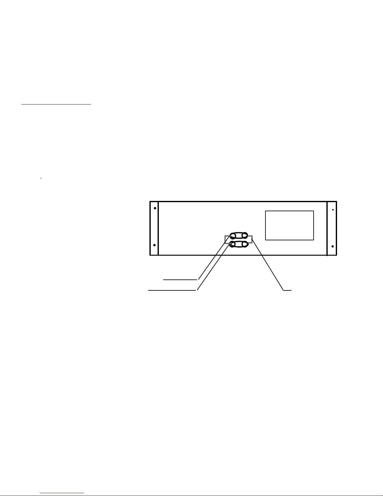
The high frequency performance of the LFTs can be tailored with the
tweeter lever control. A jumper is mounted under the crossover cover.
There are three tweeter level positions. If the jumper is disconnected, the
treble energy is rolled off slightly and this is the lowest setting. When the
jumper is connected to the third terminal up from the bottom of the right
hand row of six terminal points, the tweeter output at its middle position.
The highest tweeter level setting is achieved when the jumper is moved up
one terminal to the fourth one. It is best to start with the tweeter level
jumper disconnected, position the speakers for the best overall frequency
balance, and the decide if more high frequency energy is needed.
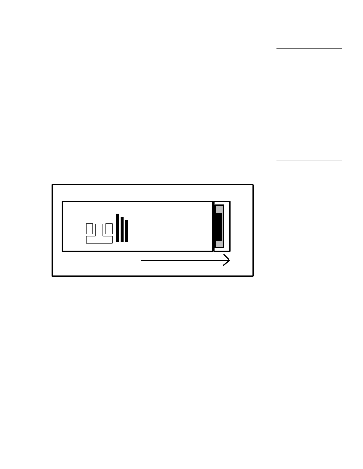
Overall imaging depends primarily on the distance separating the two
speakers relative to their distance from the preferred listening position; it is
also affected by the degree of toe-in. We cannot accurately predict what
will work best in your listening room, and can suggest only that you begin
with the drawing on the previous page as a starting point or general
guideline. Keep in mind that the parameters that affect frequency balance
also tend to affect imaging properties, and vice versa, so it is best to adjust
speaker placement in small increments and to note carefully all of the
changes effected by each shift in position before proceeding further.
The LFT-6 is wired for 6-Ohm operation, and is appropriate for use with
most higher-powered tube and solid-state amplifiers. The efficiency is
83dB with a 2.83 volt drive (1 “8” Ohm watt). This efficiency rating is
lower than average. However, the LFT radiates a planar wavefront, and as
such its apparent efficiency at the listening position is higher than the
numerical rating implies. The LFT-6 has a minimum requirement of 100
watts per side, whether tube or solid-state. It can handle “music power”
levels (short-term bursts) of 500 watts or more without difficulty. In
general, the limit of the speaker is only reached when the diaphragm
actually “bottoms out” against the magnets.
The above minimum requirements are really only estimates and depend on
listening taste and the listening environment. More power will be required
if the listening room is large, or if average sound pressure levels higher than
90 dB are desired.
The Tweeter Level
Control
Imaging
Amplifier
Requirements

6
The LFT-6is configured to allow bi-wiring or bi-amping with a minimum of
trouble. The two pairs of inputs on the crossover are connected together
internally, hot to hot and ground to ground. During normal use, speaker
cables can be connected to either the top or bottom pair of inputs.
For bi-wiring or bi-amping, the internal jumpers connecting the upper and
lower input terminals must be severed. Remove the four phillips-head
screws that hold the crossover cover in place and carefully remove the
cover; there is just enough slack in the wiring between the speaker and the
cover to allow this. Sever the two jumper wires with cutting pliers and
bend them slightly so they cannot contact one another or touch the metal
cover. Severing the jumpers divides the inputs so that now the lower
terminals power the low /midfrequency drivers, and the upper terminals
power the high frequency drivers. Both pairs of inputs continue to power
their drivers through the internal crossover, which cannot be bypassed.
JUMPERS INSIDE
TWEETER INPUT
MID/WOOFER
INPUT
Bi-wiring simply means connecting a single stereo amplifier (or two mono
amps) to a pair of speakers by using two pairs of speaker cables. Connect
the hot and ground conductors of a pair of cables to the same output
terminals on one channel of the amplifier; the other ends are connected to
the now-separate woofer/mid and tweeter inputs of the LFT. (All speaker
cables should be the same length.) The effects of bi-wiring tend to be
subtle, the slight improvement may be worth the relatively modest cost of
an extra pair or speaker cables. Bi-wiring also permits experimenting with
different types of cables for the two inputs; you may find that one type is
best-suited for bass\mid performance, while another works best on the
treble side.
Bi-Wiring and Bi-
Amping
Cutting the
Terminal Jumpers

7
Bi-amping requires and additional stereo amplifier or pair of mono amps.
You will also need some means of insuring that only the desired portion of
the frequency range reaches each amplifier. The simplest way to
accomplish this is with an external electronic crossover; however, this can
also be done by hard-wiring low-pass and high-pass filters into the inputs
of the bass/mid and treble amplifiers, respectively. For the low/mid-
frequency amp, a 10kHz low-pass filter (6 dB/octave) is required; for the
treble amp, a 10kHz. high-pass filter (also 6 dB/octave) is required. If you
wish to pursue this method, your dealer or the manufacturer of your
amplifiers should be able to help you determine the specific parts necessary.
Note that you will also need a level control on either one of the stereo
amps or on the crossover, regardless of which approach you take to bi-
amping.
Bi-Amping

8
The Eminent Technology Linear Field Transducer is a
full-range, push-pull, dynamic planar loudspeaker. In
a sense, it is the magnetic equivalent of a push-pull
electrostatic loudspeaker, differing in that it requires
no step-up transformer or bias voltage, and that the
audio signal is applied directly to its diaphragm.
the LFT-VI
To fully understand the strengths of the LFT design, one must first
consider the design and operation of this speaker's three most notable
Technical
Description

9
antecedents: the push-pull electrostatic loudspeaker (ESL); the traditional,
single-ended planar magnetic loudspeaker, and the ribbon loudspeaker.

10
The electrostatic starts with a very thin (half mil or less) diaphragm made
of mylar or a similar material, to which a light coating of mildly conductive
substance such as graphite has been applied. This diaphragm is suspended
on a rigid frame and sandwiched between two stationary conductive grids
(usually perforated metal plates) called stators.
FRAME
REAR STATOR
RESISTOR
TRANSFORMER +
--
TO
AMPLIFIER
TO BIAS
VOLTAGE
SUPPLY
[PERFORATED
METAL PLATE]
FRONT
STATOR
CONDUCTIVE
DIAPHRAM
A DC charge of high voltage (in the thousands of volts) but very low
current, known as the bias voltage, is applied to the conductive diaphragm
and kept constant. A step-up transformer is introduced to increase the
usable voltage of the amplifier's output (while simultaneously decreasing
the current), and the two ends of the transformer's output coil are
connected to the two stators.
As the amplifier produces a continuously varying AC voltage, (the
amplified music signal), the charge on the two stators will also
continuously change in synchronization with the music; and since the two
stators are connected to two different ends of the transformer's output, one
stator will take on a predominantly negative charge at the same time and to
the same extent that the other stator takes on a predominantly positive
charge. The constant-charge diaphragm will thus undergo a continuously
changing state of attraction to and repulsion from the two stators as their
polarization changes, and it is this motion that excites the air to the front
and rear of the speaker and produces sound.
Electrostatic
Loudspeakers

11
The traditional planar magnetic also starts with a thin mylar diaphragm, one
side of which is coated with adhesive and fitted with an aluminum wire
voice grid, (analogous to the voice coil of a conventional cone driver). The
diaphragm is held taut in a metal frame. On the front of this frame is a
large sheet of perforated metal, to which rows of vertically aligned strip
magnets have been fastened.
+
-
TO AMPLIFIER
FRAME
DIAPHRAM
VOICE GRID
[ACTUALLY A
CONTINUIOS LOOP]
PERMANENT
STRIP
MAGNETS
PERFORATED
METAL
SHEET
N
S
S
S
N
SINGLE-ENDED PLANAR MAGNETIC
[TOP VIEW CROSS-SECTION]
Spacing exaggerated to show detail
From there, the operation of a single-ended planar magnetic loudspeaker is
remarkably similar to that of a conventional cone driver: The amplifier's
output is sent directly through the voice grid and, because it is suspended
within a stationary magnetic field, the grid moves back and forth within
that field in synchronization with the AC voltage that is the amplified music
signal. Since the voice grid is permanently fastened to a taut diaphragm,
the diaphragm also moves in synchronization with the music signal,
exciting the air and producing sound.
Planar Magnetic
Loudspeakers

12
The third and final antecedent to consider is the ribbon: a distinctly
different sort of transducer, but one that is similar (in principle, at least) to
the single-ended planar magnetic. The ribbon’s primary distinction is that
its “diaphragm” and “voice element” are one and the same.
A ribbon driver is based on a long, narrow strip of conductive material; in
practice, thus far, all true ribbons have used a strip of very thin corrugated
aluminum for this purpose. The two ends of this strip are electrically
connected to the amplifier’s output, and are physically anchored such that
the strip is suspended within a stationary magnetic field--with said magnets
positioned at the edges of the strip.
PERMANENT MAGNET
PERMANENT MAGNET
ALUMINUM
RIBBON
ELEMENT
N
S
_
+
TO AMPLIFIER
[LEADS CONNECTED TO
TOP AND BOTTOM OF
RIBBON ELEMENT]
RIBBON DRIVER
[TOP VIEW CROSS-SECTION]
The operating principle is straightforward from there: the amplifier’s
output passes directly through the aluminum strip--which, because it is
suspended within a permanent magnetic field, moves back and forth in
synchronization with the signal, producing sound.
Ribbon
Loudspeakers

13
Not surprisingly, each of the approaches described above has its own
unique set of pros and cons. The electrostatic, because its diaphragm is so
thin and light, offers exceptionally good transient response and
reproduction of subtle, low-level musical detail. And, because it is a true
push-pull device (i.e., its diaphragm is, by design, driven from both the
front and the rear), the ESL operates in a linear fashion. Typically, gross
distortion results only when the driving amplifier clips into the speaker, or
when, in an attempt to play the speaker louder than its design allows, its
step-up transformer reaches a point of saturation.
On the negative side of the ledger, the ESL does require passing the
amplified musical signal through a transformer, which can introduce its
own colorations and non-linearities. Also, some ESLs are prone to a
condition known as arcing: Under the conditions of stress induced by
playing an ESL loudly, it is not uncommon for an electrical spark to jump
between one stator and the diaphragm (a phenomenon exactly analogous to
lightning), burning a minute hole in the diaphragm and, over time, ruining
it.
As for the planar magnetic, its strengths are similar to those of the ESL--
although the addition of several feet of wire and an adhesive coat make for
a somewhat more massive diaphragm, limiting this design’s transient
capabilities by comparison. But the planar magnetic requires no step-up
transformer or bias voltage supply, and it has the added benefit of being an
extremely manageable load for most amplifiers. However, the most
specific drawback of the traditional planar magnetic is that it is a single-
ended (as opposed to push-pull) device: As the diaphragm’s physical
excursion increases, the voice grid moves further away from its optimal
location within the permanent magnetic field (at least in one direction).
Thus, at the very instant when this speaker is called upon to reproduce
large-amplitude waveforms, it is least able to do so without distortion.
In many ways, a ribbon driver can be an excellent performer: the moving
element (the “ribbon” itself) is extremely light, allowing good “speed” and
transient performance as well as freedom from coloration. And there is no
significant physical structure on either side of the ribbon’s radiating pattern.
The ribbon’s main problem is not one of performance but of application: it
cannot be used to reproduce low frequencies. To create a moving element
large enough to generate frequencies lower than a few hundred Hz would
mean moving opposing magnetic poles so far apart that they would no
longer exert a sufficient magnetic field over the entire area of the ribbon.
Evaluating
Earlier
Approaches
Electrostatics
Planar Magnetics
Ribbons

14
Also, when a ribbon is operated at frequencies approaching the element’s
own resonant frequency (which is naturally quite low, due to its high
compliance), the ribbon element stretches and “bows” to a point where it is
no longer within the magnetic gap. To get around either of these problems
means to move the permanent magnet structure from the edges of the
element to one entire side of the element, and/or to bond the element to a
“host” diaphragm, such as a sheet of mylar, and to clamp that diaphragm
around its perimeter. In either case the driver is no longer a ribbon; it is, in
fact, a planar magnetic. To date, no one has succeeded in creating a full
range ribbon loudspeaker.

15
Eminent Technology’s Linear Field Transducer, introduced as the
LFT, represents a new approach to the design and construction of a
high-quality loudspeaker*. It builds on the strengths of the above
designs while eliminating many of their drawbacks.
The construction of the LFT -6 begins by laminating a very thin sheet of
aluminum foil to a half-mil-thick sheet of Mylar. A voice grid pattern,
created by means of CAD (Computer-Aided Design) technology, is
silkscreened onto the foil side; the remainder of the aluminum--the part not
covered by ink from the silkscreening--is chemically etched away, in a
manner similar to the etching of traces on a printed-circuit board. The ink
is then washed away, leaving a voice grid of near-perfect uniformity. This
technique results in a diaphragm/voice coil grid that is still less than one mil
in total thickness, and also permits relatively narrow spaces between the
individual traces, so the diaphragm can be evenly driven over its entire
surface.
The magnet/frame structure developed for the LFT-6 is also unique.
Eminent Technology builds its strip magnets into individual steel channels,
the size and shape of which have been carefully designed to help “focus”
the magnetic flux lines and concentrate the strength of the magnetic field
on the appropriate area of the diaphragm/voice grid. These channels are
then welded to steel crossbars (four per drive unit, vertically spaced 6-1/2
inches apart), which in turn are bolted to the aluminum frame that holds the
diaphragm in place.
Interestingly, one of the biggest challenges faced in creating a true push-
pull dynamic speaker was not a design consideration but rather a matter of
construction difficulty: to assemble a perfectly rigid structure with very
powerful permanent magnets at the front and the rear, both sides opposing
each other with tremendous force. It was not until Eminent Technology
developed a special method for this assembly procedure that the Linear
Field Transducer became a reality.
* The design and construction of the LFT is patented.
The Linear Field
Transducer
Diaphragm
Construction
The Magnet/Frame
Structure

16
By applying such new techniques to planar loudspeaker construction,
Eminent Technology has been able to eliminate many of the flaws inherent
in earlier designs. The use of a welded channel-and-crossbar frame
dispenses with the need for perforated sheet metal (an “off-the-shelf”
material presumably used for reasons of economy and ease of
manufacture.) thus greatly improving dispersion, especially at high
frequencies.
FRAME
DIAPHRAM
PERMANENT
STRIP
MAGNETS
STEEL CROSS
BAR
STEEL
CHANNELS
VOICE GRID
CONTINUOUS
LOOPS
N
S
N
N
N
S
S
S
TO AMPLIFIER
+
_
LINEAR FIELD TRANSDUCER
[TOP VIEW CROSS-SECTION]
Spacing exaggerated to show detail
Since it is now possible to have a powerful, precisely aligned magnet
structure on both sides of the diaphragm, true push-pull operation has been
achieved: Regardless of the degree of excursion the diaphragm undergoes,
the voice element is always optimally positioned within the magnetic field.
The result is extremely linear performance throughout the audible range,
with a profound increase in dynamic range and an absolute minimum of
distortion.

17
Each LFT has five individual driver panels. The outside portion on each
panel is divided into separately driven bass and (line-source) midrange
areas, with the former operating from 400 Hz down, and the latter
operating from 400 Hz up to 10 kHz. The tweeters operate as a line source
from 10 kHz up to and beyond 20 kHz. The midrange and tweeter
sections are distinguishable by their thinner magnet structures.
the LFT-IV
Right Speaker
To 400 Hz
400 to 10KHz
10 KHz and above
All three panels operate as woofers, from 400 Hz on down. Actually, all of
the panels, including the “woofers,” are physically capable of operating to
beyond 20 kHz, but would exhibit undesirable diffraction effects and poor
dispersion if allowed to do so, which is why the panels are segmented into
different sections for different portions of the frequency range. The use of
a flat panel design maintains excellent phase response throughout the
audible range.
The LFT-6 can be made to operate at almost any impedance; our present
choice of a nominal 6-Ohm impedance has been made in the interest of
maximizing efficiency and amplifier compatibility. Because of the large
Panel Frequencies
LFT Impedance

18
surface area of the panels and the resulting good heat dissipation (a
function also of the material choice for the voice grid), the LFT-6 can
handle tremendous amounts of power before any risk of damage.

19
Power Requirements: 100 watts minimum
Sensitivity 83 dB (pink noise, 20-20 kHz) at 1
watt/1 meter (2.83 V)
Frequency Response 38 Hz-20 kHz ±4 dB (typical room,
close-mic measurement)
-10 dB at 35 kHz
Phase Accuracy ± 20° 100 Hz-31 kHz
High Frequency Level Flat, -6 dB, -12 dB at 20 kHz
smooth rolloff
Impedance 6 Ohm rating
Maximum SPL 105 dB at 1 meter
Magnet type Ceramic 8
Diaphragm Area 420 in2 (front)
Harmonic Distortion Less than .04%, 100 Hz-20 kHz, 90
dB, 1 meter
Dimensions 18" wide by 78" high by 1" thick
Shipping Weight 95 lbs. each
Foil thickness .00033"
Mylar thickness .0005"
Laminate Adhesive Thickness .00015"
Gap Between Conductors .03"
Peak-to-Peak Diaphragm
Displacement .4" Woofer .035 Tweeter
Warranty 3 years parts, 1 year labor
Finish Oak standard
Walnut and other painted finishes
optional
Music All of the above done for the
enjoyment of music.
Specifications

20
Designers David Collie and Bruce Thigpen
Table of contents
Other Eminent Speakers manuals

Eminent
Eminent LFT-VIII User manual

Eminent
Eminent Ewent EW3516 User manual

Eminent
Eminent Ewent EW3516 Instructions for use

Eminent
Eminent LFT-VIII Use and care manual

Eminent
Eminent ewent EW3515 User manual

Eminent
Eminent LFT-8b User manual

Eminent
Eminent LFT XII User manual

Eminent
Eminent LFT-3 User manual

Eminent
Eminent LFT-8b Use and care manual

Eminent
Eminent LFT-11 User manual