Emirel A1-13-Y User manual

Viale Caduti per la Libertà, 4/B - 40050 MONTE S. PIETRO - BOLOGNA (ITALY)
Release 20/07/21
A1-13-Y LIMITATORE DI COPPIA
(È UN SOTTOEQUIPAGGIAMENTO DELL’A1-13).
MULTIGAMMA: 15A, 20A, 25A, 30A, 35A
PER MOTORE TRIFASE ALIMENTATO DA INVERTER
ATTENZIONE
L'impostazione dei parametri di funzionamento avviene
tramite l'uso dei tasti UP DOWN e MODE posti sul
frontale del dispositivo.
In caso di parametro numerico (per esempio il tempo
T1) il setup avviene in maniera "circolare" in salita o
discesa a seconda che si stia premendo il tasto UP o
quello DOWN.
Se il parametro che si sta modificando non è di tipo
numerico ma per esempio ha solo due (o più) possibili
stati, premendo i tasti UP e DOWN si visualizzeranno
alternativamente le due (o più) opzioni.
Nel prosieguo del documento tra i simboli [ ] verrà
riportata la lettera identificativa della schermata del
parametro considerato. Esempio: T1 [f1] indica che T1
è visualizzato nella schermata “ f1”.
PER MAGGIORI DETTAGLI CONSULTARE IL
“MANUALE A1-13” ALLEGATO AL DISPOSITIVO.
DEFINIZIONE
Il dispositivo realizza il controllo della corrente di un motore
asincrono trifase alimentato da un INVERTER, su tutta la
gamma di frequenza di lavoro.
La misura della corrente avviene facendo passare uno dei 3
conduttori che alimentano il motore entro l'A1-13-Y.
UTILIZZAZIONE
Sollevamento di carichi (gru, paranchi, ecc…) ventilatori,
pompe per liquidi ecc…
A1-13-Y TORQUE LIMITER
(IT IS A VERSION OF THE A1-13).
MULTIRANGE: 15A, 20A, 25A, 30A, 35A
FOR THREE PHASE MOTOR POWERED WITH
INVERTER
Fig. 1
PLEASE NOTE
The setup operations are made using UP, DOWN and
MODE keys placed on the front panel of the device.
In the case of numerical parameter (for example time
T1), the setup is done in a "circular" upward or
downward mode, depending on which UP or DOWN
keys is pressed.
If the parameter is not numeric but, for example, has
two (or more) possible states, using UP and DOWN
buttons the device will display alternatively the two
(or more) options.
In the following of this document, between the
symbols [ ], will be shown the identify letter of the
screen of the parameter considered.
Example: T1 [f1] indicates that T1 is displayed in the
screen “f1”.
FOR MORE DETAILS REFER TO THE “A1-13
MANUAL” ANNEX TO THE DEVICE.
DEFINITION
The device measures the current of a three phase
asynchronous motor powered by an INVERTER, on the
whole range of the working frequency.
The current measurement is done by passing one of the 3
wires of the motor through the hole of the A1-13-Y.
USE
Lifting equipment (cranes, hoists, etc ...) fans, pumps for
liquids, etc. ...
Fig. 2
AT
T
E
NZIONE: V
e
rranno
riparati in g
aranzia,
franco ns sede, i dispositivi guasti per difetti sui materi
ali, entro
24
me
si dalla
data
d
i con
segna
. Emirel non è
in alcun caso responsabile
per danni, diretti o indiretti, a persone o cose, che derivano da: mancato funzionamento, manomissioni, uso errato od improprio dei propri dispositivi di Protezione e Controllo.
Per le app
licazion
i "in
S
ICURE
ZZA"
si consiglia l
'uso di sistemi di SICUREZZA o l'uso d
i
tecniche di "RIDONDANZA".
WARNING: Repairs in guarantee are made free our factory, within 24 months from the delivery date, for the devices not working due to defects of the components. In no case Emirel can be held
responsible for damages, direct or indirect, occurred to things or people in consequence of wrong connections, accidents, not correct use or not operation of the Protection and Control devices of its
own production. For the "safety applications", it is suggested to apply SAFETY systems or REDUNDANCY engineering.".

Viale Caduti per la Libertà, 4/B - 40050 MONTE S. PIETRO - BOLOGNA (ITALY)
2Tel. 051/6761552 - Internet: http://www.emirel.it - E-mail: [email protected] / [email protected]
CARATTERISTICHE E REGOLAZIONI
Il dispositivo prevede 2 soglie:
- S1 di MASSIMA
- S2 può essere programmata di MASSIMA, di minima o
messa a OFF (la programmazione di minima può
servire per riconoscere la MARCIA a SECCO, la
programmazione di MASSIMA può servire per avere un
PRIMO ALLARME DI INCEPPAMENTO e un
SECONDO ALLARME).
Alla soglia 1 è associato il led A1 e il TIMER T1.
Alla soglia 2 è associato il led A2 e il TIMER T2.
Gli spunti iniziali possono essere tacitati da TC.
TC (0-120 sec) [f5]
Tempo di cecità iniziale allo spunto della corrente. Rende
cieco il dispositivo all'avviamento del motore.
Questo parametro è modificabile con i tasti UP e DOWN
portandosi nella schermata di SET "f5".
T1 (0-120 sec) [f1]
Al supero di S il timer si attiva, il led A1 lampeggia, se al
termine di T1 il supero permane il led A1 passa a luce piena
e il relè RA va OFF.
T2 (0-120 sec) [f2]
Al supero di S2 il timer si attiva, il led A2 lampeggia, se al
termine di T2 il supero permane, il led A2 passa a luce
piena e il relè RB va OFF.
I0 [B]
Sul frontale è previsto il trimmer I0 che permette di sottrarre
dall’uscita analogica il valore della corrente con CARICO
ZERO.
Il DISPLAY ha 2x8 caratteri su cui è possibile scorrere le
varie schermate di visualizzazione e impostazione para-
metri mediante il pulsante MODE.
Con i pulsanti UP e DOWN è possibile modificare i valori in
alcune schermate e mediante il pulsante AUTO è possibile
effettuare l'AUTO SET del valore di corrente S1 ed S2.
L’A1-13-Y ha 5 gamme di corrente (15A/20A/25A/30A/35A)
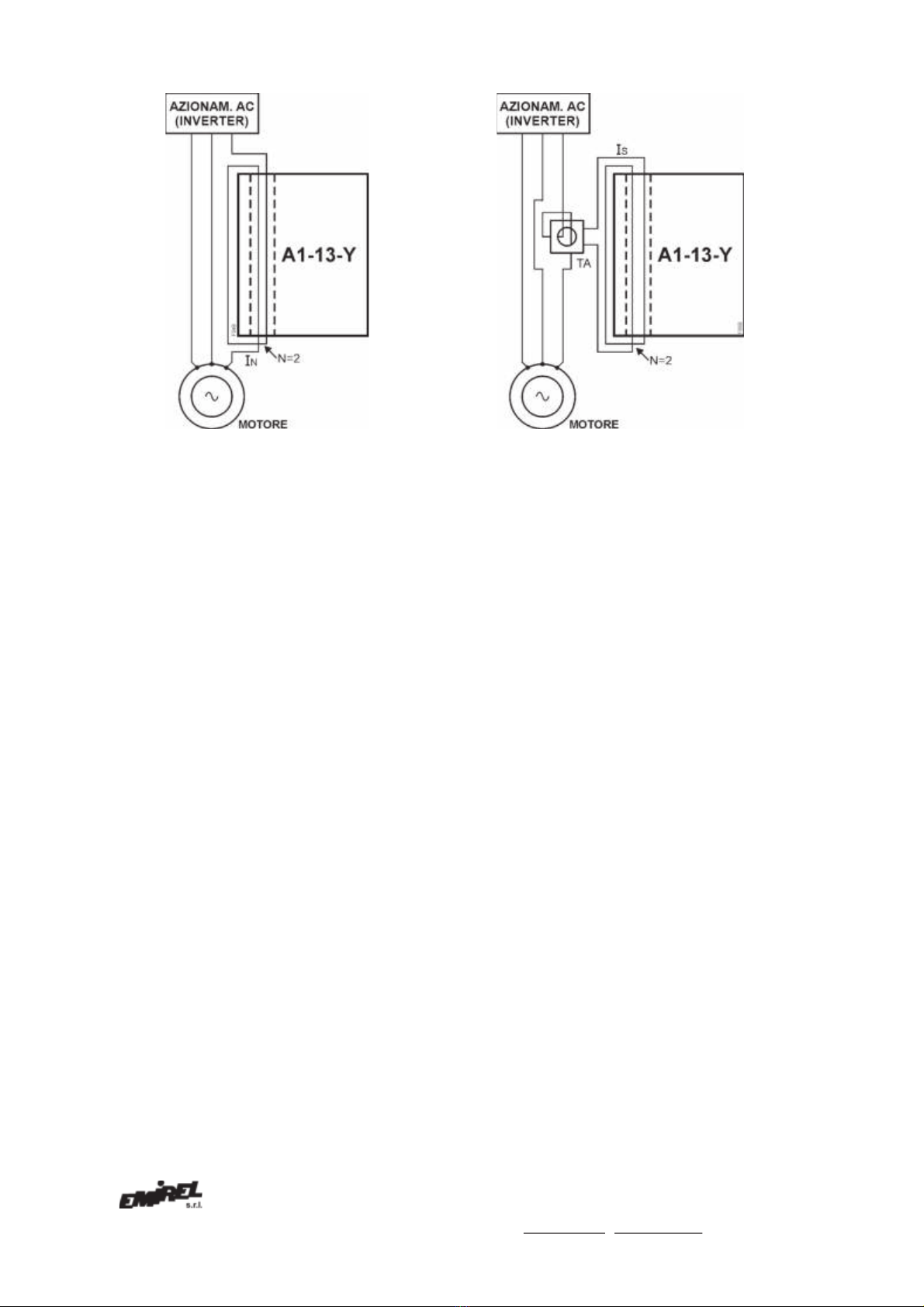
selezionabili nella schermata “a”, quindi per correnti <35A
l’inserzione è diretta e il filo di corrente IN passerà entro il
foro verticale praticato nell’A1-13-Y (Ved. Fig. 4 e 4-B).
Per correnti >35A si usa un TA esterno (Ved. Fig. 5 e 5-B).
Richiamiamo alcune grandezze dei TA.
Un TA è caratterizzato dalla corrente:
IP (massima corrente misurabile, in ingresso)
Is (corrente secondaria ridotta in uscita)
RR (rapporto di riduzione)
Un TA 50/5 ha IP=50A, Is=5A e RR=50/5=10
Se la IP=40A, la Is si ricava dalla proporzione:
50A : 5A = 40 : Is Is=_5x40_ = 4A.
50
In TAB. A sono riportati alcuni casi di programmazione del-
l’A1-13-Y.
Se la IN è <35A si devono usare le 5 GAMME dell’A1-13-Y.
Per IN<15A si ricava il rapporto _15A _, la cui parte intera
IN
indica il numero “N” di passaggi del filo entro il foro del-
l’A1-13-Y (Ved. Fig. 4-B).
Es. IN=3,6 , _15_=4,1 , quindi N=4.
3,6
In questi casi sull’A1-13-Y si programmerà RR=1 (non c’è
TECHINICAL FEATURES AND REGULATIONS
The device has 2 set points:
- MAX set point S1
- S2 can be set as MAX, min or OFF set point (the
setting as min set point can be useful to detect the
DRY RUNNING, the setting as MAX set point can be
useful to have an ALARM FOR CLOGGING and a
second ALARM).
The set point 1 is associated with the led A1 and the
TIMER T1.
The set point 2 is associated with the led A2 and the
TIMER T2.
Initial current spikes can be bypassed by TC.
TC (0-120 secs) [f5]
Initial timer (0-120 secs) adjustable by UP and DOWN
keys into the SET screen "f5".
It makes the device "blind" at the current starting, in order
to bypass the current spike at the motor start up.
T1 (0-120 secs) [f1]
When S is overcome, the timer is activated, the led A1
flashes, if at the end of T1 the overcoming remains, the
led A1 will be lit and the relay RA goes OFF.
T2 (0-120 secs) [f2]
When S2 is overcome, the timer is activated, the led A2
flashes, if at the end of T2 the overcoming remains, the
led A2 will be lit and the relay RB goes OFF.
I0 [B]
On the panel of the device there is a trimmer I0 which
allows to subtract the value of the current with ZERO
LOAD from the analog output.
The DISPLAY has 2x8 characters, using the MODE
button the user can surf through the different screens.
Using the UP and DOWN keys the user can change the
values in some SET screens.
Using the AUTO key, the user can make the AUTO SET
of S1 and S2 current value.
The A1-13-Y has 5 current ranges (15A/20A/25A/30A/
35A) selectable in the “a” screen, therefore for currents
<35A the insertion is direct and the current wire IN will
pass through the vertical hole present in the A1-13-Y
(See Fig. 4 and 4-B).
For currents >35A an external CT is used (See Fig. 5 and
5-B).
Some quantities of CTs are indicated hereunder.
A CT is characterized by the current:
IP (maximum measurable input current)
Is (reduced secondary output current)
RR (reduction ratio)
A CT 50/5 has IP=50A, Is=5A and RR=50/5=10
If the IP=40A, the Is is obtained from the proportion:
50A : 5A = 40 : Is Is= _5x40_ = 4A.
50
The TAB. A shows some programming cases of the
A1-13-Y.
If the IN is <35A, the 5 RANGES of the A1-13-Y must be
used.
With IN<15A the ratio _15A _ is obtained, this number,
IN
without the decimals, is the number "N" of passages of
the
wire inside
the hole
of the A1
-
13
-
Y (See
Fig. 4
-
B).

Viale Caduti per la Libertà, 4/B - 40050 MONTE S. PIETRO - BOLOGNA (ITALY)
TA esterno), N=4 e FS=15A.
Se IN>35A serve un TA esterno, che supponiamo sia xx/5
quindi si userà il FS=15A e il filo che porta Is farà almeno
N=3 passaggi nell’A1-13-Y (Ved. Fig. 5).
Es. IN=41A si sceglie TA 50/5, (RR=10)
Is= _5x41_= 4,1A N= _15A_= 3,6 N=3
50 4,1
La programmazione per l’A1-13-Y sarà RR=10, N=3,
FS=15A.
Es. IN=68A si sceglie TA 100/5, (RR=20)
Is= _5x68_= 3,4A N= _15A_= 4,4 N=4
50 3,4
La programmazione per l’A1-13-Y sarà RR=20, N=4,
FS=15A.
Se fosse disponibile un TA 200/5 (RR=40) 200A/68A=2,9
per utilizzare meglio il TA conviene far passare 2 volte il filo
di corrente entro il TA quindi:
IN=68Ax2=136A, 200A : 5A = 136A : Is
Is= _5Ax136A_ = 3,4A N= _15A_= 4,4 N=4
200 3,4
In questo caso, per tener conto dei 2 passaggi del filo di
corrente entro il TA esterno, la programmazione per
A1-13-Y sarà:
RR= _40_= 20, N=4, FS=15A.
2
Es. IN=81A si sceglie TA 100/5, (RR=20)
Is= _5x81_= 4,05A N= _15A_= 3,7 N=3
100 4,05
La programmazione per l’A1-13-Y sarà RR=20, N=3,
FS=15A.
Es. IN=81A ma si sceglie TA 200/5 (RR=40)
200A/81A= 2,46, il filo di corrente passerà 2 volte entro il TA
esterno, quindi IN=81Ax2=162A 200A : 5A = 162A : Is
Is= _5x162A_ = 4,05A N= _15A_= 3,7 N=3
200 4,05
La programmazione sarà: RR= _40_= 20, N=3, FS=15A.
2
Es. IN=99A si sceglie TA 100/5, (RR=20)
Is= _5x99_= 4,95A N= _15A_= 3,03 N=3
100 4,95
La programmazione sarà RR=20, N=3, FS=15A.
Es. IN=99A ma si sceglie TA 200/5 (RR=40)
200A/99A= 2,02, il filo di corrente passerà 2 volte entro il TA
esterno, quindi IN=99Ax2=198A 200A : 5A = 198A : Is
Is= _5x198A_ = 4,95A N= _15A_= 3,03 N=3
200 4,95
La programmazione sarà: RR= _40_= 20, N=3, FS=15A.
2
NOTA 1:
La colonna denominata “uscita analogica” mostra il peso in
Ampere che deve essere attribuito ad ogni “volt” dell’uscita
analogica a seconda del motore utilizzato.
Ex. IN=3,6 , _15_=4,1 , therefore N=4.
3,6
In these cases, on the A1-13-Y, RR=1 must be
programmed (there is not external CT), N=4 and
FS= 15A.
If IN>35A an external CT must be used, considering a CT
xx/5 so FS=15A, the wire carrying Is will make at least
N=3 passages in the A1-13-Y (See Fig. 5).
Ex. IN=41A with CT 50/5, (RR = 10)
Is = _5x41_ = 4,1A N= _15A_ = 3,6 N=3
50 4,1
The programming for the A1-13-Y will be RR=10, N=3,
FS=15A.
Ex. IN=68A with CT 100/5, (RR=20)
Is= _5x68_= 3,4A N= _15A_= 4,4 N=4
50 3,4
The programming for the A1-13-Y will be RR=20, N=4,
FS=15A.
If a CT 200/5 is available (RR=40) 200A/68A=2,9
to use better the CT, 2 wire passages inside the CT are
recommended, so:
IN=68Ax2=136A, 200A : 5A = 136A : Is
Is= _5Ax136A_ = 3,4A N= _15A_= 4,4 N=4
200 3,4
In this case, to take the 2 wire passages inside the
external CT into account, the programming of the
A1-13-Y will be:
RR= _40_= 20, N=4, FS=15A.
2
Ex. IN=81A with CT 100/5, (RR=20)
Is= _5x81_= 4,05A N= _15A_= 3,7 N=3
100 4,05
The programming of the A1-13-Y will be RR=20, N=3,
FS=15A.
Ex. IN=81A but with TA 200/5 (RR=40)
200A/81A= 2,46, the current wire will pass through the
external CT 2 times, therefore IN=81Ax2=162A
200A : 5A = 162A : Is
Is= _5x162A_ = 4,05A N= _15A_= 3,7 N=3
200 4,05
The programming will be: RR= _40_= 20, N=3, FS=15A.
2
Ex. IN=99A with CT 100/5, (RR=20)
Is= _5x99_= 4,95A N= _15A_= 3,03 N=3
100 4,95
The programming will be RR=20, N=3, FS=15A.
Ex. IN=99A but with CT 200/5 (RR=40)
200A/99A= 2,02, the current wire will pass through the
external CT 2 times, therefore IN=99Ax2=198A
200A : 5A = 198A : Is
Is= _5x198A_ = 4,95A N= _15A_= 3,03 N=3
200 4,95
The programming will be: RR= _40_= 20, N=3, FS=15A.
2
REMARK 1:
The column called “analog output” shows the weight in
Ampere that must be assigned to each “volt” of the analog
output.

Viale Caduti per la Libertà, 4/B - 40050 MONTE S. PIETRO - BOLOGNA (ITALY)
4Tel. 051/6761552 - Internet: http://www.emirel.it - E-mail: [email protected] / [email protected]
Fig. 4
Fig. 5
TAB. A
V
D
=400 Vac A1-13-Y
IN (A)
n
TA est.
Ext. CT
RR
N
FS(A)
Uscita analogica
Analog output
1V
®
x,x A
2,6
-
-
1
5
15
1V
®
0,3A
3,6 - - 1 4
15 1V
®
0,37A
5 - - 1 3
15 1V
®
0,5A
6,6 - - 1 2
15 1V
®
0,75A
8,5 - - 1 1
15 1V
®
1,5A
11,3 - - 1 1
15 1V
®
1,5A
15,2
-
-
1
1
15
1V
®
1,5A
21,7 - - 1 1
25 1V
®
2,5A
29
,3
-
-
1
1
30
1V
®
3,0A
35 - - 1 1
35 1V
®
3,5A
41 1 50/5 10 3
15 1V
®
5,0A
68 1 100/5 20 4
15 1V
®
10,0A
68 2 200/5 20 4
15 1V
®
10,0A
81 1 100/5 20 3
15 1V
®
10,0A
81 2 200/5 20 3
15 1V
®
10,0A
99
1
100/5
20
3
15
1V
®
10,0A
99 2 200/5 20 3
15 1V
®
10,0A
Viale Caduti per la Libertà, 4/B - 40050 MONTE S. PIETRO - BOLOGNA (ITALY)
Fig. 4-B
VISUALIZZAZIONI
LED A1
E' attivo con la soglia S1.
Lampeggia al supero della soglia S1 e dopo il tempo di
ritardo T1 passerà a luce piena e il relè A apre il suo
contatto.
LED A2 (attivo solo se S2 è di MASSIMA o di minima)
E' attivo con la soglia S2.
Lampeggia al supero della soglia S2.
Dopo il tempo di ritardo passerà a luce piena e il relè B apre
il suo contatto.
Il LED A4 è collegato alle operazioni di memorizzazione
tramite AUTO, quando si esegue la memorizzazione di
un parametro il led si accenderà momentaneamente e
contestualmente sul display apparirà il messaggio
"MEM".
TARATURA
SET POINT S1
Portarsi nella schermata [l].
L'utente ha due modi per impostare la soglia S1:
1) A motore fermo.
Entrare nel menù SET.
Inserire la pwd.
Portarsi nella schermata "l" impostare il valore di S1
desiderato.
2) Posizionarsi nella schermata "A".
Premere il tasto AUTO.
Inserire la password.
Avviare il motore e portarlo al punto di funzionamento
desiderato.
Premere il tasto AUTO fino a quando non apparirà sullo
schermo la scritta MEM e il L4 non si accenderà.
Spegnere il motore ed eventualmente ritoccare la soglia S1
memorizzata con i tasti UP e DOWN.
SET POINT S2 (se di MASSIMA o di minima)
Portarsi alla schermata [m] e scegliere se S2 è di minima o
di MASSIMA.
Portarsi nella schermata [n].
L'ut
ente
ha d
u
e modi per impostare la soglia
S
2
:
Fig. 5-B
VISUALIZATIONS
LED A1
A1 is active with the set point S1.
The led A1 flashes when the current I overcomes the set
point S1.
After the delay time T1 the led A1 will be lit and the relay A
opens its contact.
LED A2 (active only if S2 is set as MAX or min set
point)
A2 is active with the set point S2.
The led A2 flashes when the set point S2 is overcome.
After the delay time, the led A2 will be lit and the relay B
opens its contact.
The LED A4 is connected to the storage operations
using AUTO key, when the user stores a parameter,
the LED will light momentarily and simultaneously on
the display the message "MEM" is present.
SETTING
SET POINT S1
The user must go to the [l] screen.
The user has two ways to set the set point S1:
1) The motor is OFF.
Enter the SET menu.
Enter the PASSWORD.
Go to the "l" screen to set the desired value of S1.
2) Go to the "A" screen.
Press AUTO key.
Enter the PASSWORD.
Start the motor and bring it to the desired operating point.
Press AUTO key until "MEM" message appears on the
screen and the L4 will not turn on.
Turn off the engine and if necessary, adjust the set point
S1 stored with the UP and DOWN keys.
SET POINT S2 (if it is set as MAX or min)
The user must go to the [m] screen and select S2 as min
set point or MAX set point.
The user must go to the [n] screen.
The us
er has tw
o ways to
set the set point
S
2
:

Viale Caduti per la Libertà, 4/B - 40050 MONTE S. PIETRO - BOLOGNA (ITALY)
6Tel. 051/6761552 - Internet: http://www.emirel.it - E-mail: [email protected] / [email protected]
1) A motore fermo.
Entrare nel menù SET.
Inserire la pwd.
Portarsi nella schermata "n" impostare il valore di S2
desiderato.
2) Posizionarsi nella schermata "A".
Premere il tasto AUTO.
Inserire la password.
Avviare il motore e portarlo al punto di funzionamento
desiderato.
Premere il tasto AUTO fino a quando non apparirà sullo
schermo la scritta MEM e il L4 non si accenderà.
Spegnere il motore ed eventualmente ritoccare la soglia S2
memorizzata con i tasti UP e DOWN.
RIPRISTINO [b]: A seconda dell'impostazione del para-
metro "Alm" nella schermata di setup "b", il dispositivo
risulterà a ripristino automatico o no, in questo secondo
caso per il reset degli allarmi si dovrà utilizzare il contatto
esterno di TELERESET (pin 16-12) o premere contempo-
raneamente i pulsanti UP e DOWN (bisogna essere nella
schermata "A").
SICUREZZA INTRINSECA
I relé interni sono normalmente ON e vanno OFF in caso di
allarme.
TELERESET: pin 16-12 la chiusura momentanea di un
contatto NA (libero da tensione) resetta ogni allarme
presente (la stessa funzione si ottiene premendo contempo-
raneamente UP e DOWN).
COLLEGAMENTI ELETTRICI
A vite per filo fino 1,5mm2(14 AWG).
(Collegamento a un quadro elettrico con differenziale e
sezionatore).
La lunghezza di ogni collegamento deve essere < 30m.
INSTALLAZIONE:
In caso di inserzione diretta vedi fig. 4 e 4-B.
In caso di uso di TA esterno vedi fig. 5 e 5-B.
USCITE:
relè A pin 6-7 3A 230 Vac (carico res.)
relè B pin 8-9 3A 230 Vac (carico res.)
USCITA ANALOGICA [h]:
TENSIONE: 0-10 V pin 3(+) - 12 R carico: maggiore
10 kOhm.
L’uscita analogica è disponibile per una visualizzazione
esterna o per una registrazione dati.
ALIMENTAZIONE:
pin 1-2 6VA 50-60 Hz ±10%, 230 Vac, oppure 24Vac
DIMENSIONI: 100x 75 x110 mm per guida DIN
TEMPERATURA FUNZ.: 0-60°C
PESO: kg 0,600 - COLORE: grigio
MISURE DI SICUREZZA
Il dispositivo DEVE essere installato esclusivamente
all’interno di un quadro elettrico chiuso mediante chiave o
dispositivo analogo.
L’accesso al suddetto quadro e di conseguenza al
dispositivo DEVE essere effettuato esclusivamente a quadro
disalimentato e SOLO dal personale di manutenzione o di
installazione opportunatamente formato ed addestrato alla
operazione prevista.
Per la pulizia usare un panno imbevuto di detergenti privi di:
Alcool denaturato, Benzene, Alcool isopropilico.
COMPATIBILITA' ELETTRO
MAGNETICA
Electromagnetic compatibility
CEI
-
EN 61326
-
1
“BASSA TENSIONE” - LVD
LVD – “LOW VOLTAGE”
CEI-EN 61010-1
1) The motor is OFF.
Enter the SET menu.
Enter the PASSWORD.
Go to the "n" screen to set the desired value of S2.
2) Go to the "A" screen.
Press AUTO key.
Enter the PASSWORD.
Start the motor and bring it to the desired operating point.
Press AUTO key until "MEM" message appears on the
screen and the L4 will not turn on.
Turn off the engine and if necessary, adjust the set point
S2 stored with the UP and DOWN keys.
RESET [b]: Depending on the setting of the parameter
"Alm" in the SET screen "b", the device will have the
automatic reset or not, in the latter case to reset the
alarms the user could use the external TELERESET (pins
16-12) or press simultaneously the UP and DOWN keys
(the user must be in screen "A").
POSITIVE SAFETY
The internal relays are normally ON and they go OFF
when the set point is overcome.
TELERESET: the temporary closing of a contact (voltage
free) between pins 16-12 resets every alarm (the same
function as pressing UP and DOWN keys at the same time
in the screen "A").
CONNECTIONS
Screw connections for cables up to 1,5mm2(14 AWG).
(Wiring to an electrical board with a differential relay and a
sectionalizing switch).
The length of every wiring must be less than 30m.
INSTALLATION :
In case of direct insertion see fig. 4 and 4-B.
In case of use of an external CT see fig. 5 and 5-B.
OUTPUTS :
relay A pin 6-7 3A 230 Vac (resistive load)
relay B pin 8-9 3A 230 Vac (resistive load)
ANALOG OUTPUT [h]:
VOLTAGE: 0-10 V pin 3(+) - 12 R load: greater than
10 kOhm.
The analog output is available for an external display or for
a data recording.
SUPPLY: pin 1-2 6VA 50-60 Hz ±10%, 230 Vac, or
24Vac
DIMENSIONS: 100x75 x110mm DIN rail
OPERATING TEMP.: 0-60°C
WEIGHT: kg 0,600 - COLOUR: grey
SECURITY MEASURES
The device MUST be installed only inside an electrical
panel closed by a key or similar device.
Access to this electrical panel and consequently at the
device MUST be done exclusively with panel switched off
and ONLY by maintenance or installation personnel
suitably formed and trained for the planned operation.
For cleaning use a cloth soaked with detergents without:
Denatured Alcohol, Benzene, Isopropyl alcohol.

Viale Caduti per la Libertà, 4/B - 40050 MONTE S. PIETRO - BOLOGNA (ITALY)
IMPOSTAZIONE PARAMETRI DI
FUNZIONAMENTO
Mediante tasti UP e DOWN presenti sul frontale del
dispositivo.
Mediante tasti UP e DOWN presenti sul frontale del
dispositivo e automaticamente se in modalità
“auto-apprendimento”.
Dopo 45 secondi di inattività su una pagina il dispositivo
tornerà automaticamente alla pagina 1
Di seguito è riportata la successione delle schermate di
visualizzazione e impostazione del
dispositivo e il loro funzionamento:
SETTING FUNCTIONING
PARAMETERS
Using UP and DOWN keys on the front panel of the
device.
Using UP and DOWN keys on the front panel of the
device and automatically in case of AUTOSET mode
of operation
After 45 seconds of inactivity on a page the device will
automatically return to page 1
The following is a description of the operation of each
device window.
1 I
=
x
x
. x
A
F
=
x
x
H
z
In questa schermata sono visualizzate la
corrente istantanea I del motore e la sua
frequenza F
Le frequenze operative del dispositivo
vanno da una minima di 3 Hz ad una
massima di 150 Hz.
This screen displays the current I
absorbed by the electric motor and its
operating frequency F.
The operating frequency of the device
ranging from a minimum of 3 Hz to a
maximum of 150 Hz.
2 S
1
=
x
x
. x
A
S
2
=
x
x
. x
A
In questa schermata sono visualizzate la
soglie di intervento S1 ed S2. La soglia
S2 può essere settata di minima o di
MASSIMA
This screen displays the intervention
thresholds S1 and S2.
The S2 threshold can be set for
minimum or MAXIMUM intervention.
3
I
0
=
x
x
. x
A
U
a
=
I
I
-
I
0
La corrente I0 (impostabile
manualmente con il trimmer frontale)
può rappresentare la corrente a vuoto
del motore stesso. Per una corretta
impostazione si può far funzionare il
motore a vuoto e contestualmente agire
sul trimmer frontale fino a quando sul
display del dispositivo I e I0 non
avranno lo stesso valore.
In questa schermata è visualizzata la
scelta operata circa l’uscita analogica (0-
10V). E’ possibile avere in uscita solo
l’indicazione dell’effettiva corrente
istantanea I del motore oppure il valore
di I-I0 dove I0 rappresenta la corrente a
vuoto del motore, in pratica la corrente
“persa” del motore stesso.
The current I0 (can be manually set with
the front trimmer) can represent the
motor no-load current. For a correct
setting, the motor can be run without
load and set the front trimmer until the I
and I0 on the display have the same
value.
This screen displays the choice made
about the analog output (0-10V). It is
possible to have at the output only the
indication of the motor actual
instantaneous current I, or the value of
I-I0 where I0 represents the motor no-
load current, in practice the "lost"
current of the motor itself.
4
5 S
E
T
E
p
w
d
=
x
x
x
In questa schermata è possibile inserire
la password per poter accedere al menù
di configurazione del dispositivo. La pwd
può variare tra 0 e 999 . Se si inserisce
la pwd errata con la pressione del tasto
MODE si tornerà alla schermata A
Pwd di default PWD=01
In this screen the user can enter the
password to access the SET menu of the
device.
The password can be modified between
0 and 999.
If a wrong password has been entered
by pressing the MODE key the device
returns to the screen "A" .
The default value is PWD=01
Viale Caduti per la Libertà, 4/B - 40050 MONTE S. PIETRO - BOLOGNA (ITALY)
8Tel. 051/6761552 - Internet: http://www.emirel.it - E-mail: [email protected] / [email protected]
6
S
E
T
a
F
S
=
1
5
A
S
E
T
a
F
S
=
2
0
A
S
E
T
a
F
S
=
2
5
A
S
E
T
a
F
S
=
3
0
A
S
E
T
a
F
S
=
3
5
A
Default : FS=15ª
In questa schermata viene impostato il
valore di fondo scala di funzionamento
del dispositivo.
Le soglie di allarme sono dipendenti dal
valore di fondo scala impostato.
E’ necessario scegliere il fondo scala più
appropriato in funzione della taglia del
motore.
In caso di utilizzo di un TA esterno viene
automaticamente selezionato FS=15. Per
una maggiore precisione è opportuno
fare 3 passaggi del filo del secondario
del TA esterno all'interno del TA dell'A1-
13 (ovviamente impostando poi N=3
nell'apposita schermata)
In this screen the user can set the FS
value of the full scale of the device.
The alarm set-points are dependent on
the FS value set.
It is necessary to choose the most
appropriate FS value depending of the
size of the electric motor.
In case of using an external CT is
automatically selected FS = 15 and the
user must do three pass through the
device's hole.
After that, N=3 must be selected in the
“d” SET screen.
7
S
E
T
B
A
l m
=
m
a
n
a
u
t
Default : Alm = aut
Questa schermata consente di impostare
il tipo di ripristino del dispositivo dopo un
allarme.
Aut: appena cessa la condizione di
allarme il dispositivo si riabiliterà
Man: per resettare il dispositivo sarà
necessario agire sul reset esterno o su
quello frontale.
In this screen the user can set the type
of device reset.
Aut: automatic reset at the end of the
alarm condition
Man: manual reset, using the external
contact or the reset key on the front
panel of the device
9
S
E
T
d
N
=
x
Default : N=1
N è il numero di passaggi nel TA del
cavo della corrente che si vuole
misurare. N è variabile da 1 a 5
Esempio: Se uso un motore da 7A posso
selezionare FS=15A e fare N=2 passaggi
nel TA oppure posso selezionare FS=35
e fare 5 passaggi nel TA
N is the number of passes through the
hole of the device's CT of the current
cable that we want to measure. N is
variable from 1 to 5.
Example: In case of motor with IN=7A
select
FS = 15A and N = 2.
Otherwise, the user can select FS = 35A
and N = 5.
10
S
E
T
e
R
R
=
x
x
x
Default : RR=1
RR è il rapporto spire del TA esterno che
si deve usare quando la corrente del
motore è maggiore di 35A
1 < RR < 100
Esempio: in caso di TA esterno 100/5,
RR=100/5=20
RR is the turns ratio of the external CT
that should be used when the motor
current is greater than 35A.
1 < RR < 100
Example: In case of 100/5 CT,
RR=100/5=20
11
S
E
T
f 1
T
1
=
x
x
x
s
Default : T1= 5 sec
Tempo di ritardo di allarme della soglia
di allarme S1
T1 varia da 0 a 120 sec
the a
larm delay time of the alarm
threshold S1
T1 varies from 0 to 120 sec
12
S
E
T
f 2
T
2
=
x
x
x
s
Default : T2= 5 sec
Tempo di ritardo di allarme della soglia
di allarme S2
T2 varia da 0 a 120 sec
the a
larm
dela
y time of the alarm
threshold S2/s2
T2 varies from 0 to 120 sec
13
14
15
S
E
T
f 5
T
c
=
x
x
x
s
Default : Tc= 1 sec
Tempo di cecità allo spunto del motore.
Tc varia da 0 a 120 sec
Time delay at the start of the motor in
order to avoid the initial current spike.
0 < Tc < 120 sec
16
S
E
T
g
I
N
=
x
x
A
Default : IN= 35A
Corrente di targa del motore.
1 < IN < 500A
Per motori più grandi di FS=35A è
necessario usare un TA esterno
Rated motor current IN (see the motor
plate)
1 < IN < 500A
In case of electric motor with IN > 35A
an external CT is needed.
17
S
E
T
h
U
a
-
>
I
S
E
T
h
U
a
-
>
I
-
I
0
Default : Ua -> I
Schermata di scelta del tipo di uscite
analogica desiderata.
Agendo sui tasti UP e DOWN è possibile
scegliere se avere a disposizione in
uscita I o (I-I0)
In this screen the user could choose
which measure is shown in the analog
output.
Using the UP and DOWN keys it is
possible to select I or I-I0.
1
8

Viale Caduti per la Libertà, 4/B - 40050 MONTE S. PIETRO - BOLOGNA (ITALY)
19
20
21
S
E
T
l
S
1
=
x
x
. x
A
Default : S1= 10.0A
S1 è il valore di soglia di allarme di MAX
corrente
Quando I > S1 il led A1 si accenderà e
dopo il tempo T1 il relè RA andrà off.
S1 is the current MAX alarm threshold
value
When I > S1 the led A1 will turn on and
after the time T1 the relay RA will go off.
22
S
E
T
m
S
s
2
=
m
i n
M
A
X
O
F
F
Default : s2= min
Schermata di impostazione del
funzionamento della soglia S2
MAX – min – OFF (soglia disabilitata)
Screen for setting the operation of MAX
or min of the S2 threshold
MAX – min – OFF
23
S
E
T
n
S
2
=
x
x
. x
A
Default : S2= 5.0A
S2 è il valore di soglia di allarme di
min / MAX corrente
Quando I > S2 se S2 di MAX o I < s2 se
s2 è impostata di min il led A2 si
accenderà e dopo il tempo T2 il relè RB
andrà off.
S2 is the current Min / MAX alarm
threshold value
When I > S2 if S2 of MAX or I < s2 if s2
is set to min, led A2 will switch on and
after T2 time the relay RB will go off.
38
S
E
T
p
p
w
d
=
x
x
x
Default : pwd= 001
Pagina di inserimento password,
variabile tra 0 e 999
Password entry page, variable between
0 and 999
39
40 S
E
T
r
E
n
d
Fine del menù di configurazione.
End of the SET menu.
APPROFONDIME
NTO SPIEGAZIONE SCHERMATE
A1-13-Y
Si possono identificare n° 2 Movimenti circolari:
I° movimento fra le prime 4 SCHERMATE DI
VISUALIZZAZIONE, attivata da “MODE”;
II° movimento fra le 14 sc
hermate di SET, attivato da
“MODE”.
Quando ci si accinge a programmare il dispositivo con l’aiuto
della TAB. A si devono essere già decise le grandezze:
IN = corrente del motore
RR = rapporto riduzione TA
N = numero di passaggi del filo di corrente entro l’A1-13-Y
FS = Fondo Scala (15A / 20A / 25A / 30A / 35A)
Per il valore delle soglie S1 ed s2 è possibile applicare
l’AUTOAPPRENDIMENTO dal motore in moto, come descritto
al punto TARATURA. Schermate led m.
Per schermata “A” si intende la prima schermata,
senza
lettera, quella con Corrente e Frequenza.
NOTA 1:
Nella schermata “h” si evidenzia il seguente fenomeno: in un
motore, quando è caricato al suo massimo (100%) la
corrente è IN, quando non è caricato (0%) la corrente non è
ØA, ma ha un valore I0, che può essere anche 1/3
IN, quindi
la corrente utile va da I0ad IN (Es.: IN=9A, I0=3A
, la gamma
di corrente utile è 9A-3A = 6A).
Nella schermata “h” si può scegliere se sull’uscita Ana
logica
sarà riportato il valore di I o il valore I-I0.
Ricordiamo che l’UA può servire per
visualizzare il carico del
motore o per realizzare altre soglie.
NOTA 2: VALORI di DEFAULT per A1-13-Y :
S1 = 10A, s2=5A, RR = 1, N=1; FS = 15A, T1 = 5s.,
T2 = 5s., TC = 1s.; PWD = 01.
FURTHER EXPLANATIONS ABOUT A1-13-Y
SCREENS
2 circular Movements can be identified:
I° movement among the first
4 DISPLAY SCREENS,
activated by “MODE”;
II°
movement among the 14 SET screens, activated by
“MODE”.
When the user programs the device on the basis of the
TAB. A, the physical quantities must be already decided:
IN = motor current
RR = CT reduction ratio
N = number of passages of the current wire inside the
hole of the A1-13-Y
FS = Full Scale (15A / 20A / 25A / 30A / 35A)
For the value of the set points S1 and s2
it is possible to
apply the SELF-LEARNING from the running motor
, as
described in the SETTING paragraph. land m screens.
“A” screen is
the first screen, without letter, the one with
Current and Frequency.
REMARK 1:
In the "h" screen there is the following phenomenon
: in a
motor, when it is loaded to its maximum (100%)
the
current is IN, when i
t is not loaded (0%) the current is
not ØA but has a value I0
, which can also be 1/3 IN, so
the useful current goes from I0to IN (Ex.: IN=9A, I0=
3A,
the range of useful current is 9A-3A = 6A).
In the “h” screen the user can choose whether
the value
of I or the value I- I0 will be shown on the Analog Output.
We remind the user that the Analog Output can be use
d
to display the motor load or to create other set points.
REMARK 2:DEFAULT VALUES for A1-13-Y :
S1 = 10A, s2=5A, RR = 1, N=1; FS = 15A, T1 = 5s.,
T2
= 5s
.
, TC = 1s
.
; PW
D = 01.
Table of contents
Other Emirel Protection Device manuals


