Raychem XL-Trace User manual

2. Fire Sprinkler
System Freeze
Protection
1. Pipe Freeze
Protection and
Flow Maintenance
3. Roof and Gutter
De-Icing
4. Surface Snow
Melting – MI
5. Surface Snow
Melting and Anti-
Icing – ElectroMelt
6. Freezer Frost
Heave Prevention
7. Floor Heating 8. Technical Data
Sheets
H55838 2/12 www.tycothermal.com 1 of 44
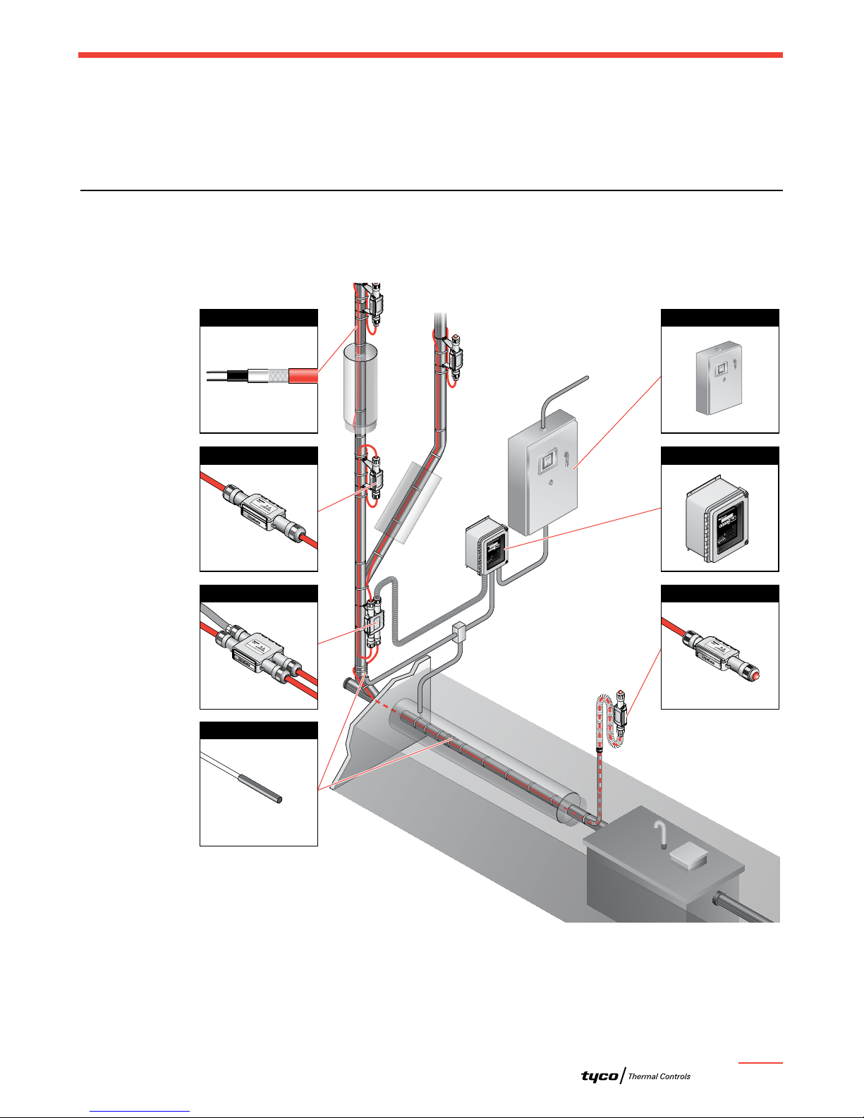
Pipe Freeze Protection
and Flow Maintenance
This step-by-step design guide provides the tools necessary to design a Raychem XL-Trace
pipe freeze protection or flow maintenance system. For other applications or for design
assistance, contact your Tyco Thermal Controls representative or phone Tyco Thermal
Controls at (800)545-6258. Also, visit our web site at www.tycothermal.com.
Contents
Introduction..............................................................1
How to Use this Guide ....................................................2
Safety Guidelines ........................................................2
Warranty...............................................................3
System Overview..........................................................3
XL-Trace Applications.....................................................3
Self-Regulating Heating Cable Construction ....................................4
Pipe Freeze Protection Applications ...........................................5
Typical Pipe Freeze Protection System ........................................5
General Water Piping .....................................................6
Fire Sprinkler Systems ....................................................8
Flow Maintenance Applications ...............................................9
Typical Flow Maintenance System ...........................................9
Greasy Waste Lines .....................................................10
Fuel Lines .............................................................12
Pipe Freeze Protection and Flow Maintenance Design.............................13
Design Step by Step .....................................................13
Step 1 Determine design conditions and pipe heat loss .....................13
Step 2Select the heating cable .......................................18
Step 3Determine the heating cable length ..............................20
Step 4Determine the electrical parameters..............................22
Step 5Select the connection kits and accessories ........................26
Step 6Select the control system......................................31
Step 7Select the power distribution . . . . . . . . . . . . . . . . . . . . . . . . . . . . . . . . . . . 33
Step 8Complete the Bill of Materials ...................................36
XL-Trace System Pipe Freeze Protection and Flow Maintenance Design Worksheet ......37
Introduction
Raychem XL-Trace is designed for pipe freeze protection and flow maintenance in the
following applications:
• Freeze protection of general water piping (aboveground and buried)
• Freeze protection of fire sprinkler systems (aboveground and buried supply pipes)
• Flow waste lines (aboveground and buried)
• Flow maintenance of fuel lines (aboveground)
XL-Trace System

PIPE FREEZE PROTECTION AND FLOW MAINTENANCE
2 of 44 www.tycothermal.com H55838 2/12
This guide does not cover applications in which any of the following conditions exist:
• Hazardous locations, as defined in the national electrical codes
• Pipe temperature other than specified in Table 1 on page 3
• Pipe maintenance temperatures above 150°F (65°C)
• Supply voltage other than 120 V or 208–277 V
If your application conditions are different, or if you have any questions, contact your
Tyco Thermal Controls representative or contact Tyco Thermal Controls directly
at (800)545-6258.
How to Use this Guide
This design guide presents Tyco Thermal Controls’ recommendations for designing an XL-Trace
pipe freeze protection or flow maintenance system. It provides design and performance data,
electrical sizing information, and application configuration suggestions. Following these
recommendations will result in a reliable, energy-efficient system.
OTHER REQUIRED DOCUMENTS
This guide is not intended to provide comprehensive installation instructions. For complete
XL-Trace pipe freeze protection and flow maintenance system installation instructions, please
refer to the following additional required documents:
• XL-Trace System Installation and Operation Manual (H58033)
• Additional installation instructions are included with the connection kits, thermostats,
controllers, and accessories
If you do not have these documents, you can obtain them from the Tyco Thermal Controls
web site at www.tycothermal.com.
For products and applications not covered by this design guide, please contact your Tyco
Thermal Controls representative or call Tyco Thermal Controls directly at (800)545-6258.
Safety Guidelines
As with any electrical equipment, the safety and reliability of any system depends on the
quality of the products selected and the manner in which they are installed and maintained.
Incorrect design, handling, installation, or maintenance of any of the system connection kits
could damage the system and may result in inadequate performance, overheating, electric
shock, or fire. To minimize these risks and to ensure that the system performs reliably, read
and carefully follow the information, warnings, and instructions in this guide.
This symbol identifies important instructions or information.
This symbol identifies particularly important safety warnings that must be followed.
WARNING: To minimize the danger of fire from sustained electrical arcing if the
heating cable is damaged or improperly installed, and to comply with the requirements of
Tyco Thermal Controls, agency certifications, and national electrical codes, ground-fault
equipment protection must be used on each heating cable branch circuit. Arcing may not
be stopped by conventional circuit protection.
H55838 2/12 www.tycothermal.com 3 of 44
2. Fire Sprinkler
System Freeze
Protection
1. Pipe Freeze
Protection and
Flow Maintenance
3. Roof and Gutter
De-Icing
4. Surface Snow
Melting – MI
5. Surface Snow
Melting and Anti-
Icing – ElectroMelt
6. Freezer Frost
Heave Prevention
7. Floor Heating 8. Technical Data
Sheets
System Overview
Warranty
Tyco Thermal Controls’ standard limited warranty applies to all products.
An extension of the limited warranty period to ten (10) years from the date of installation is
available if a properly completed online warranty form is submitted within thirty (30) days
from the date of installation. You can access the complete warranty on our web site at
www.tycothermal.com.
System Overview
The XL-Trace system provides freeze protection and flow maintenance for aboveground
and buried pipe applications. The XL-Trace system is based on self-regulating heating cable
technology. Tyco Thermal Controls offers the option of three self-regulating heating cables
with the XL-Trace system: 5XL, 8XL, and 12XL (208–277 V only) for applications using 120 and
208–277 V power supplies. The cable’s output is reduced automatically as the pipe warms,
so there is no possibility of failure due to overheating.
An XL-Trace system includes the heating cable, power connection, splice, tee connections,
controls, contactors, power distribution panels, accessories, and the tools necessary
for a complete installation.
XL-Trace Applications
Identify which of the standard XL-Trace applications below pertain to your installation.
Proceed to the appropriate design sections that follow.
Table 1 XL-Trace Applications
Application Description
Specific application
requirements
Pipe freeze protection
General water piping Freeze protection (40°F [4°C]
minimum) of insulated, metal or
plastic water piping
“Aboveground piping,” page 6
“Buried piping,” page 7
Sprinkler piping Freeze protection (40°F [4°C]
minimum) of standpipes up to
20", supply pipes and branch lines
with sprinklers
“Standpipes, supply pipes, and
branch lines with sprinklers” on
page 8. Also see “XL-Trace
System for Fire Sprinkler Freeze
Protection Design Guide” (H58489).
Flow maintenance
Greasy waste lines Flow maintenance (110°F [43°C]
minimum) for insulated greasy
waste lines
“Aboveground piping” on page 10
“Buried piping” on page 11
Fuel lines Flow maintenance (40°F [4°C]
minimum) for insulated metal
piping containing #2 fuel oil
“For aboveground piping only,”
page 12
Note: If your application does not fit these guidelines, contact your local Tyco Thermal
Controls representative or call (800) 545-6258.
PIPE FREEZE PROTECTION AND FLOW MAINTENANCE
4 of 44 www.tycothermal.com H55838 2/12
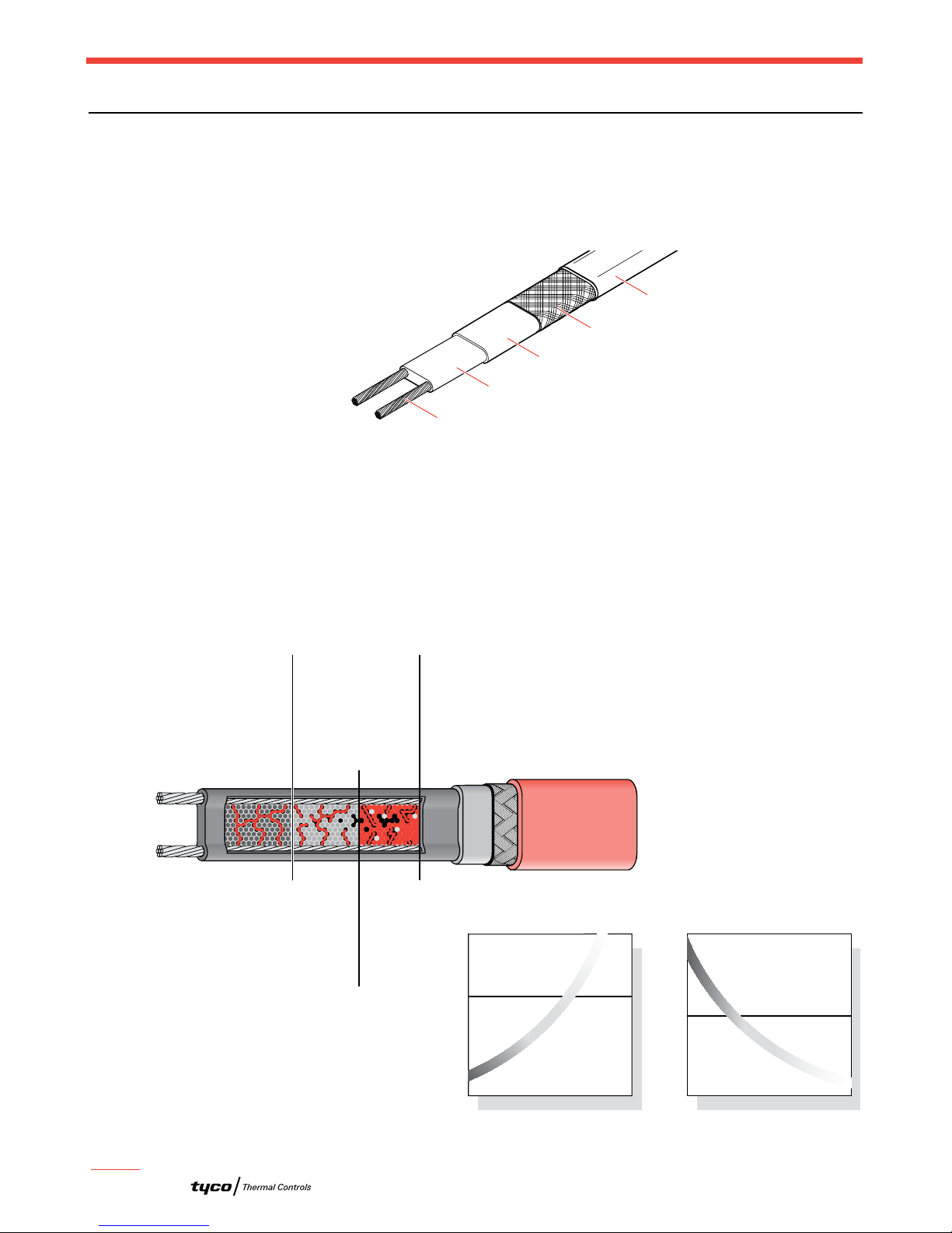
Self-Regulating Heating Cable Construction
Raychem XL-Trace self-regulating heating cables are comprised of two parallel nickel-coated
bus wires in a cross-linked polymer core, a tinned copper braid, and a fluoropolymer or
polyolefin outer jacket. These cables are cut to length, simplifying the application design and
installation.
Fig. 1 XL-Trace heating cable construction
With self-regulating technology, the number of electrical paths between bus wires changes in
response to temperature fluctuations. As the temperature surrounding the heater decreases,
the conductive core contracts microscopically. This contraction decreases electrical resis-
tance and creates numerous electrical paths between the bus wires. Current flows across
these paths to warm the core.
As the temperature rises, the core expands microscopically. This expansion increases
electrical resistance and the number of electrical paths decreases. The heating cable
automatically reduces its output.
At low temperature,
there are many
conducting paths,
resulting in high output
and rapid heat-up. Heat
is generated only when it
is needed and precisely
where it is needed.
At high temperature,
there are few conducting
paths and output is
correspondingly lower,
conserving energy
during operation.
At moderate temperature,
there are fewer conducting
paths because the heating
cable efficiently adjusts by
decreasing output, eliminating
any possibility of overheating.
The following graphs illustrate the response of self-regulating heating cables to
changes in temperature. As the temperature rises, electrical resistance increases,
and our heaters reduce their power output.
Temperature
Resistance
Power
Temperature
Constant wattage
Constant wattage
Self-regulating
Self-regulating
Fig. 2 Self-regulating heating cable technology
Nickel-plated copper bus wire
Self-regulating conductive core
Modified polyolefin inner jacket
Tinned-copper braid
Polyolefin or
fluoropolymer outer jacket

H55838 2/12 www.tycothermal.com 5 of 44
2. Fire Sprinkler
System Freeze
Protection
1. Pipe Freeze
Protection and
Flow Maintenance
3. Roof and Gutter
De-Icing
4. Surface Snow
Melting – MI
5. Surface Snow
Melting and Anti-
Icing – ElectroMelt
6. Freezer Frost
Heave Prevention
7. Floor Heating 8. Technical Data
Sheets
Pipe Freeze Protection Applications
Pipe Freeze Protection Applications
A pipe freeze protection system is designed to maintain water temperature at a minimum of
40°F (4°C) to prevent freezing.
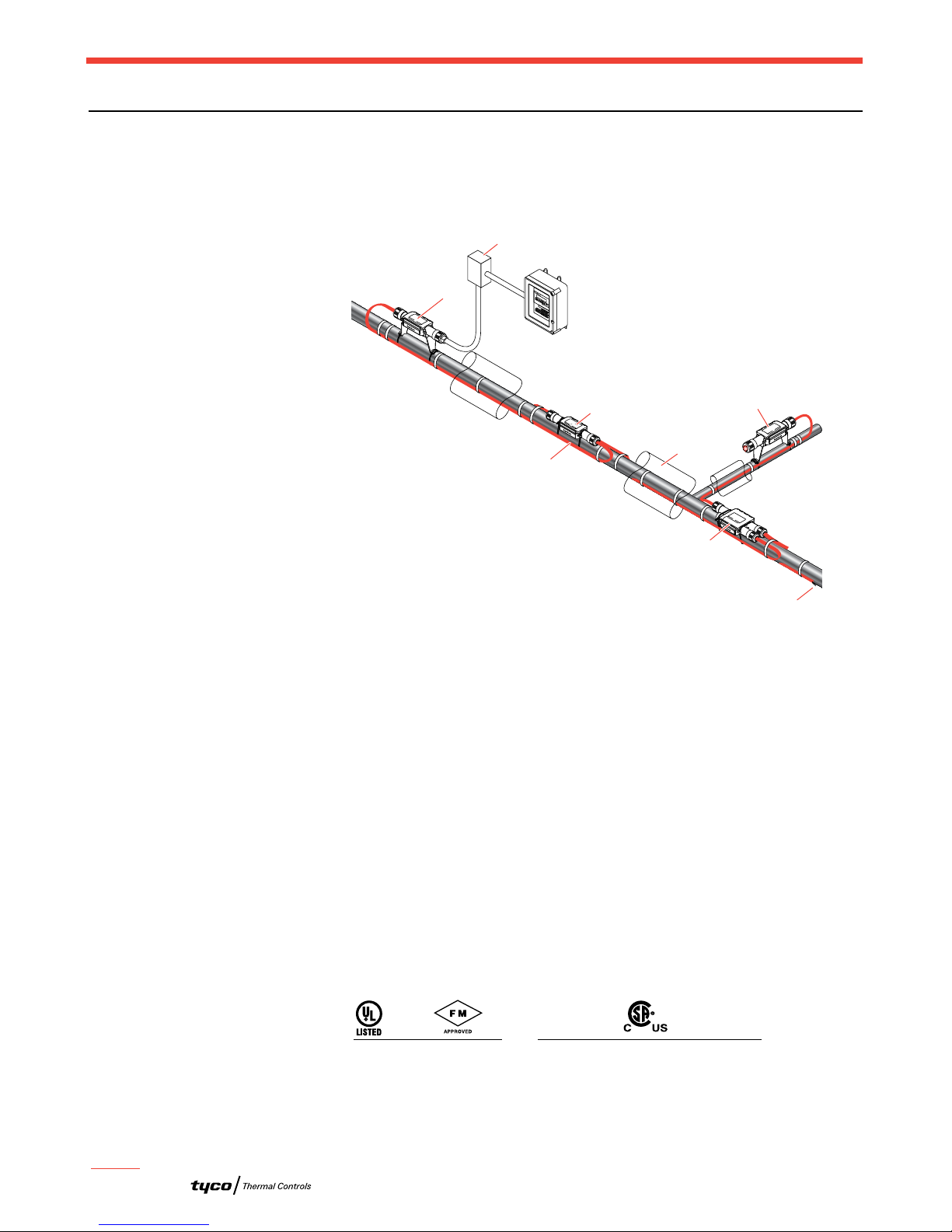
Typical Pipe Freeze Protection System
A typical pipe freeze protection system includes the XL-Trace self-regulating heating cables,
connection kits, ambient temperature control, and power distribution.
Fig. 3 Typical XL-Trace pipe freeze protection system
Lighted End Seal
Heating Cable
End Seal Kit
Tee Kit
Power Distribution Panel
Power Connection Kit Splice Kit Cross Kit
Ambient RTD
PIPE FREEZE PROTECTION AND FLOW MAINTENANCE
6 of 44 www.tycothermal.com H55838 2/12
General Water Piping
General water piping is defined as metal or plastic water piping located in nonhazardous
locations.
ABOVEGROUND PIPING
Fig. 4 Typical aboveground piping system
Application Requirements
The system complies with Tyco Thermal Controls requirements for aboveground general
water piping when:
• The heating cable is permanently secured to insulated metal pipes with GT-66 glass tape,
or to plastic pipes using AT-180 aluminum tape.
• A 30-mA ground-fault protection device (GFPD) is used.
• The heating cable is installed per manufacturer’s instructions with approved Raychem
connection kits. See Table 13 on page 27 and the XL-Trace System Installation and
Operation Manual (H58033).
Cable Selection
See “Other Required Documents” page 14.
Approvals
UL Listed, FM Approved, and c-CSA-us Certified for nonhazardous locations.
RayClic-PC
power connection
Junction
box
XL-Trace
heating cable
RayClic-S
splice
RayClic-T
tee
Insulation
RayClic-LE
lighted end seal
(optional)
RayClic-E
end seal
DigiTrace C910
Electronic controller
5XL1-CR, -CT
5XL2-CR, -CT 8XL1-CR, -CT
8XL2-CR, -CT 5XL1-CR, -CT
5XL2-CR, -CT 8XL1-CR, -CT
8XL2-CR, -CT 12XL2-CR, -CT
-w

H55838 2/12 www.tycothermal.com 7 of 44
2. Fire Sprinkler
System Freeze
Protection
1. Pipe Freeze
Protection and
Flow Maintenance
3. Roof and Gutter
De-Icing
4. Surface Snow
Melting – MI
5. Surface Snow
Melting and Anti-
Icing – ElectroMelt
6. Freezer Frost
Heave Prevention
7. Floor Heating 8. Technical Data
Sheets
Pipe Freeze Protection Applications
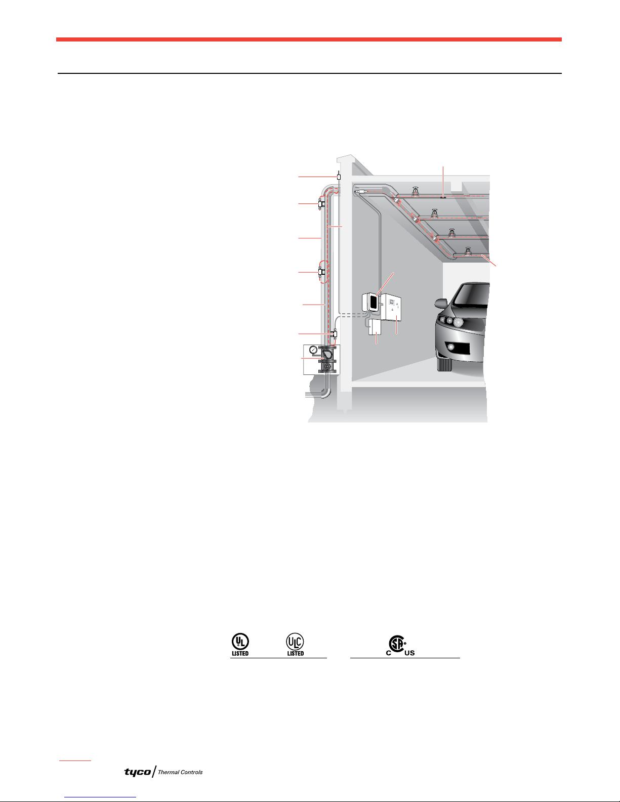
BURIED PIPING
Fig. 5 Typical buried piping system
Application Requirements
The system complies with Tyco Thermal Controls requirements for use on buried insulated
metal or plastic pipe when:
• The pipeline is buried at least 2 feet deep.
• All heating cable connections (power, splice, tee, and end termination) are made above-
ground. No buried or in-conduit splices or tees are allowed.
• The heating cable has a fluoropolymer outer jacket (-CT).
• The power connection and end seal are made in UL Listed and CSA Certified junction
boxes above grade.
• The heating cable is protected from the pipe to the power connection box in UL Listed
and CSA Certified water-sealed conduit (minimum 3/4-inch diameter) suitable for the
location.
• A 30-mA ground-fault protection device (GFPD) is used.
• Closed-cell, waterproof thermal insulation with fire-retardant, waterproof covering is used.
• The heating cable is installed per manufacturer’s instructions with approved Tyco Thermal
Controls connection kits. See Table 15 on page 29 and the XL-Trace System Installation
and Operation Manual (H58033).
Cable Selection
See “Pipe Heat Loss Calculations,” page 14.
Approvals
UL Listed, FM Approved, and c-CSA-us Certified for nonhazardous locations.
RTD10CS
Insulation
Conduit
XL-Trace
heating cable
with -CT jacket
Ground
Alternate
power connection
Alternate
end seal
Ground
Wall
RayClic-LE*
RayClic-PC*
Junction box
RayClic-E
end seal
Conduit
Wall
with wall
mounting
bracket
with wall
mounting
bracket
FTC-XC
power
connection
*To protect the heating cable run it inside
Convolex tubing between the conduit and
the RayClic connection kits.
DigiTrace C910
Electronic controller
Conduit for
temperature
sensor
5XL1-CT
5XL2-CT 8XL1-CT
8XL2-CT 5XL1-CT
5XL2-CT 8XL1-CT
8XL2-CT 12XL2-CT
-w
PIPE FREEZE PROTECTION AND FLOW MAINTENANCE
8 of 44 www.tycothermal.com H55838 2/12
Fire Sprinkler Systems
XL-Trace is designed to maintain fire suppression system standpipes, supply piping, mains,
feeders, branch lines and sprinklers at 40°F (4°C) in areas subject to freezing.
STANDPIPES, SUPPLY PIPES, AND BRANCH LINES WITH SPRINKLERS
Fig. 6 Standard sprinkler standpipe heating system layout
Refer to the Fire Sprinkler System Freeze Protection Design Guide (H58489) for detailed in-
structions to design XL-Trace heating cable circuits to freeze protect aboveground or buried
supply pipe, feeders, mains standpipes, branch lines and sprinklers.
Approvals
The 2007 edition of NFPA 13 (Standard for the Installation of Sprinkler Systems) allows List-
ed electrical heat tracing to freeze protect fire suppression systems including supply lines,
standpipes and branch lines containing sprinklers. XL-Trace is c-CSA-us Certified for use on
fire suppression systms under CSA C22.2 No. 130-03 for Canada and IEEE 515.1-2005 for
the US. The system covered in this manual includes supply lines, standpipes, branch lines
and sprinkler heads.
XL-Trace systems are also UL and ULC Listed for freeze-protecting sprinkler supply lines,
standpipes up to 20 inches in diameter and branch lines not containing sprinklers.
Standpipe
Thermal insulation
Control valves
in heated enclosure
RayClic-PC
power connection
RayClic-S splice
RayClic-LE
lighted end seal
Ambient sensing RTD
Ground
XL-Trace
Power
distribution
panel
Fire
alarm
panel
DigiTrace C910
electronic
controller
Refer to Branch
Lines with
Sprinkler section
for information on
heat tracing
sprinkler heads.
Line sensing RTD
5XL1-CR, -CT
5XL2-CR, -CT 8XL1-CR, -CT
8XL2-CR, -CT 5XL1-CR, -CT
5XL2-CR, -CT 8XL1-CR, -CT
8XL2-CR, -CT
12XL2-CR, -CT (not for branch lines
with sprinklers and sprinkler heads)
-w
H55838 2/12 www.tycothermal.com 9 of 44
2. Fire Sprinkler
System Freeze
Protection
1. Pipe Freeze
Protection and
Flow Maintenance
3. Roof and Gutter
De-Icing
4. Surface Snow
Melting – MI
5. Surface Snow
Melting and Anti-
Icing – ElectroMelt
6. Freezer Frost
Heave Prevention
7. Floor Heating 8. Technical Data
Sheets
Flow Maintenance Applications
Flow Maintenance Applications
A flow maintenance system is designed to maintain cooking greasy waste lines and #2 fuel
oil lines above the temperature at which the viscosity inhibits fluid flow.
Typical Flow Maintenance System
A typical flow maintenance system includes the XL-Trace self-regulating heating cables with
a fluoropolymer outer jacket, connection kits, line-sensing temperature control and power
distribution.
Splice Kit
Powered Tee Kit
Heating Cable
Lighted End Seal
Power Distribution Panel
Grade
Electronic Controller
RTD
Fig. 7 Typical XL-Trace flow maintenance system

PIPE FREEZE PROTECTION AND FLOW MAINTENANCE
10 of 44 www.tycothermal.com H55838 2/12
Greasy Waste Lines
Greasy waste lines are defined as piping used for the disposal of waste oils and fats created in
the cooking process. Typical applications include greasy waste lines from commercial
restaurants. A grease-line flow maintenance system is designed to maintain a 110°F (43°C)
minimum fluid temperature.
ABOVEGROUND PIPING
Fig. 8 Typical aboveground piping system
Application Requirements
The system complies with Tyco Thermal Controls requirements for aboveground greasy
waste lines when:
• The heating cable is permanently secured to metal pipes with GT-66 glass tape, or to
plastic pipes using AT-180 aluminum tape.
• The heating cable must have a fluoropolymer outer jacket (-CT).
• A 30-mA ground-fault protection device (GFPD) is used.
• Tees and splices are installed using pipe mounting brackets, not in direct contact with
piping.
• The heating cable is installed per manufacturer’s instructions with approved Tyco Thermal
Controls connection kits. See Table 13 on page 27 and the XL-Trace System Installation
and Operation Manual (H58033).
Cable Selection
See “Pipe Heat Loss Calculations,” page 14.
Approvals
XL-Trace systems (-CT only) are UL Listed, FM Approved, and c-CSA-us Certified for
nonhazardous locations.
RayClic-PC
power
connection
Junction
box
RayClic-S
splice
Insulation
RayClic-LE
lighted end seal
RayClic-E
Alternate
end seal
XL-Trace
heating cable
with -CT jacket
RayClic-SB-04
pipe mounting bracket
DigiTrace C910
Electronic controller
RTD10CS
5XL1-CT
5XL2-CT 8XL1-CT
8XL2-CT 5XL1-CT
5XL2-CT 8XL1-CT
8XL2-CT 12XL2-CT
-w

H55838 2/12 www.tycothermal.com 11 of 44
2. Fire Sprinkler
System Freeze
Protection
1. Pipe Freeze
Protection and
Flow Maintenance
3. Roof and Gutter
De-Icing
4. Surface Snow
Melting – MI
5. Surface Snow
Melting and Anti-
Icing – ElectroMelt
6. Freezer Frost
Heave Prevention
7. Floor Heating 8. Technical Data
Sheets
Flow Maintenance Applications
BURIED PIPING
Fig. 9 Typical buried greasy waste line
Application Requirements
The system complies with Tyco Thermal Controls requirements for buried greasy waste lines
when:
• The heating cable is permanently secured to metal pipes with GT-66 glass tape, or to
plastic pipes using AT-180 aluminum tape.
• The heating cable must have a fluoropolymer outer jacket (-CT).
• The pipeline is buried at least 2 feet deep.
• All heating cable splices or tees are made aboveground. No buried or in-conduit splices
or tees are allowed.
• The power connection and end seal are made in UL Listed and CSA Certified junction
boxes above grade.
• The heating cable is protected from the pipe to the power connection box in UL Listed
and CSA Certified conduit (minimum 3/4-inch diameter) suitable for the location.
• A 30-mA ground-fault protection device (GFPD) is used.
• Closed-cell, waterproof thermal insulation with fire-retardant, waterproof covering is used.
• The heating cable is installed per manufacturer’s instructions with approved Tyco Thermal
Controls connection kits. See Table 15 on page 29 and the XL-Trace System Installation
and Operation Manual (H58033).
Cable Selection
See “Heating Cable Catalog Number” on page 18.
Approvals
XL-Trace systems (-CT only) are UL Listed, FM Approved, and c-CSA-us Certified for
nonhazardous locations.
RTD10CS
Insulation
Conduit
XL-Trace
heating cable
with -CT jacket
Ground
Alternate
power connection
Alternate
end seal
Ground
Wall
RayClic-LE*
RayClic-PC*
Junction box
RayClic-E
end seal
Conduit
Wall
with wall
mounting
bracket
with wall
mounting
bracket
FTC-XC
power
connection
*To protect the heating cable run it inside
Convolex tubing between the conduit and
the RayClic connection kits.
DigiTrace C910
Electronic controller
Conduit for
temperature
sensor
5XL1-CT
5XL2-CT 8XL1-CT
8XL2-CT 5XL1-CT
5XL2-CT 8XL1-CT
8XL2-CT 12XL2-CT
-w

PIPE FREEZE PROTECTION AND FLOW MAINTENANCE
12 of 44 www.tycothermal.com H55838 2/12
Fuel Lines
Fuel lines are defined as those carrying #2 fuel oil. A fuel line flow maintenance system is
designed to maintain a 40°F (4°C) minimum fluid temperature to maintain flow.
FOR ABOVEGROUND PIPING ONLY
Fig. 10 Typical aboveground piping system
Application Requirements
The system complies with Tyco Thermal Controls requirements for aboveground #2 fuel oil
piping when:
• The heating cable is permanently secured to metal pipes with GT-66 glass tape, or to
plastic pipes using AT-180 aluminum tape.
• The heating cable must have a fluoropolymer outer jacket (-CT).
• Tees and splices are installed using pipe mounting brackets, not in direct contact with
piping.
• A 30-mA ground-fault protection device (GFPD) is used.
• The heating cable is installed per manufacturer’s instructions with approved Tyco Thermal
Controls connection kits. See Table 13 on page 27 and the XL-Trace System Installation
and Operation Manual (H58033).
Cable Selection
See “Pipe Heat Loss Calculations,” page 14.
Approvals
XL-Trace systems (-CT only) are UL Listed, FM Approved, and c-CSA-us Certified for
nonhazardous locations.
RayClic-S
splice
XL-Trace
heating cable
with -CT jacket
RTD10CS
RayClic-LE
lighted end seal
Junction
box
Insulation
RayClic-PC
power
connection
RayClic-SB-04
pipe mounting bracket
DigiTrace C910
Electronic controller
5XL1-CT
5XL2-CT 8XL1-CT
8XL2-CT 5XL1-CT
5XL2-CT 8XL1-CT
8XL2-CT 12XL2-CT
-w

H55838 2/12 www.tycothermal.com 13 of 44
2. Fire Sprinkler
System Freeze
Protection
1. Pipe Freeze
Protection and
Flow Maintenance
3. Roof and Gutter
De-Icing
4. Surface Snow
Melting – MI
5. Surface Snow
Melting and Anti-
Icing – ElectroMelt
6. Freezer Frost
Heave Prevention
7. Floor Heating 8. Technical Data
Sheets
Pipe Freeze Protection and Flow Maintenance Design
Pipe Freeze Protection and Flow Maintenance Design
This section details the design steps necessary to design your application. The examples
provided in each step are intended to incrementally illustrate the project parameter output for
two sample designs from start to finish. As you go through each step, use the “XL-Trace System
Pipe Freeze Protection and Flow Maintenance Design Worksheet,” page 37, to document your
project parameters, so that by the end of this section you will have the information you need
for your Bill of Materials.
XL-Erate, the commercial pipe freeze protection and flow maintenance design software is
available at http://www.tycothermal.com to assist with your design.
Design Step by Step
Your system design requires the following essential steps.
Determine design conditions and pipe heat loss
Select the heating cable
Determine the heating cable length
Determine the electrical parameters
Select the connection kits and accessories
Select the control system
Select the power distribution
Complete the Bill of Materials
Pipe Freeze Protection
and Flow Maintenance
1. Determine design
conditions and heat
loss
2. Select the heating
cable
3. Determine the
heating cable length
4. Determine the
electrical parameters
5. Select the
connection kits and
accessories
6. Select the control
system
7. Select the power
distribution
8. Complete the Bill of
Materials
Step Determine design conditions and pipe heat loss
Collect the following information to determine your design conditions:
• XL-Trace application (from Table 1Location
– Indoors
– Outdoors
– Aboveground
– Buried
• Maintain temperature (TM)
• Maximum system temperature (TMAX)
• Minimum ambient temperature (TA)
• Pipe diameter and material
• Pipe length
• Thermal insulation type and thickness
• Supply voltage
Example: Pipe Freeze Protection – Water Piping
Location Aboveground, outdoor
Maintain temperature (TM) 40°F (4°C)
Maximum system temperature (TMAX) 80°F (27°C)
Minimum ambient temperature (TA) –20°F (–29°C)
Pipe diameter and material 2-inch plastic
Pipe length 300 ft (91 m)
Thermal insulation type and thickness 1-inch fiberglass
Supply voltage 120 V
PIPE FREEZE PROTECTION AND FLOW MAINTENANCE
14 of 44 www.tycothermal.com H55838 2/12
Example: Pipe Freeze Protection – Greasy Waste Line
Location Buried
Maintain temperature (TM) 110°F (43°C)
Maximum system temperature (TMAX) 125°F (52°C)
Minimum ambient temperature (TA) 50°F (10°C) (soil temperature)
Pipe diameter and material 4-inch metal
Pipe length 200 ft (61 m)
Thermal insulation type and thickness 1-inch rigid cellular urethane
Supply voltage 208 V
PIPE HEAT LOSS CALCULATIONS
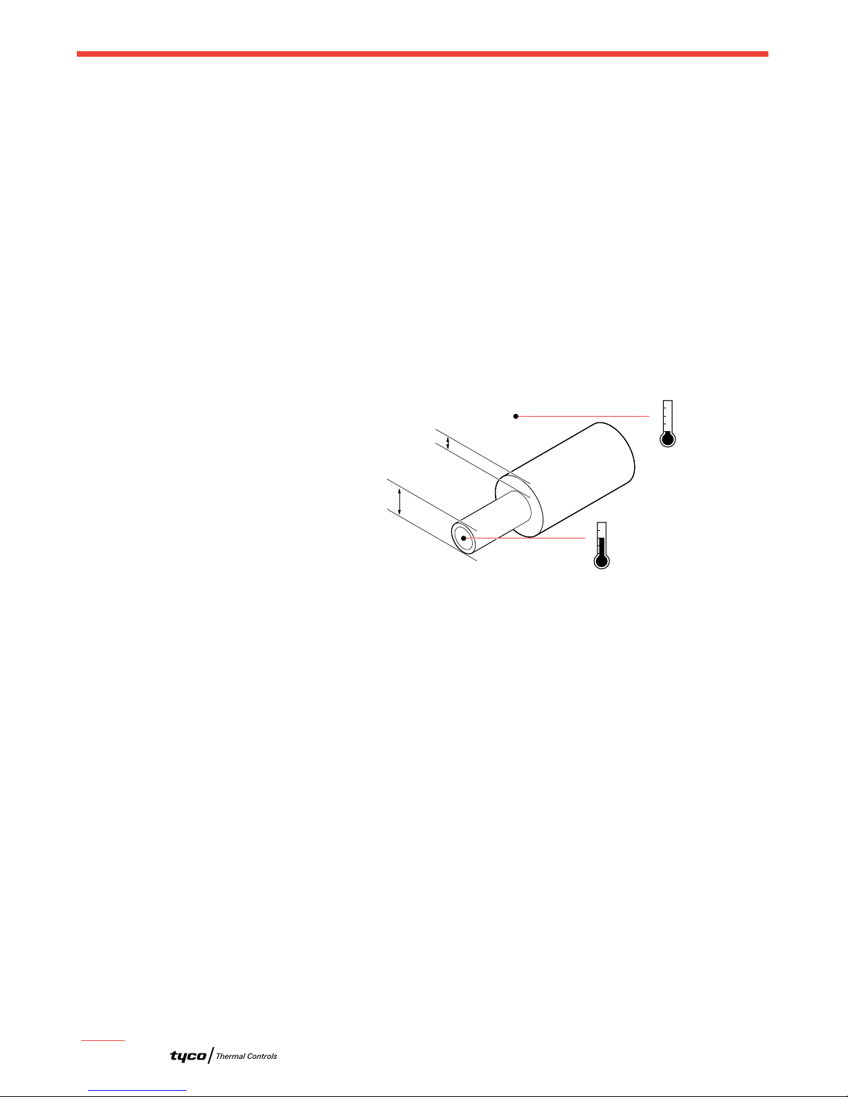
To select the proper heating cable you must first determine the pipe heat loss. To do this you
must first calculate the temperature differential (DT) between the pipe maintain temperature
and the minimum ambient temperature.
Fig. 11 Pipe heat loss
Calculate temperature differential DT
To calculate the temperature differential (DT), use the formula below:
DT = TM– TA
Example: Pipe Freeze Protection – Water Piping
TM40°F (4°C)
TA–20°F (–29°C)
DT = 40°F – (–20°F) = 60°F
DT = 4°C – (–29°F) = 33°C
Example: Flow Maintenance – Greasy Waste Line
TM110°F (43°C)
TA50°F (10°C)
DT = 110°F – (50°F) = 60°F
DT = 43°C – (10°C) = 33°C
Determine the pipe heat loss
Match the pipe size, insulation thickness, and temperature differential (DT) from Table 2 to
determine the base heat loss of the pipe (QB).
Example: Pipe Freeze Protection – Water Piping
Pipe diameter 2 inch
20
40
60
80
−40
−20
0
+20
+40
Maintain
temperature
°F
°F
Minimum
ambient
temperature
Thermal insulation thickness
Pipe or
tubing
diameter

H55838 2/12 www.tycothermal.com 15 of 44
2. Fire Sprinkler
System Freeze
Protection
1. Pipe Freeze
Protection and
Flow Maintenance
3. Roof and Gutter
De-Icing
4. Surface Snow
Melting – MI
5. Surface Snow
Melting and Anti-
Icing – ElectroMelt
6. Freezer Frost
Heave Prevention
7. Floor Heating 8. Technical Data
Sheets
Pipe Freeze Protection and Flow Maintenance Design
Insulation thickness 1 inch
DT 60°F (33°C)
Heat loss (QB) for 60°F must be calculated through interpolation between DT at 50°F and DT
at 100°F from Table 2. For difference between the DT of 50°F and the DT of 100°F:
QB-50 3.2 W/ft (from Table 2)
QB-100 6.8 W/ft (from Table 2)
DT interpolation DT 60°F is 20% of the distance between DT 50°F and DT 100°F
QB-60 QB-50 + [0.20 x (QB-100 – QB-50)] = 3.2 + [0.20 x (6.8 – 3.2)] = 3.9 W/ft
Pipe heat loss (QB)3.9 W/ft @ Tm40°F (12.9 W/m @ Tm4°C)
Example: Flow Maintenance – Greasy Waste Line
Pipe diameter 4 inch
Insulation thickness 1 inch
DT 60°F (33°C)
QBfor 60°F must be calculated through interpolation between DT at 50°F and DT at 100°F
from Table 2. For difference between the DT of 50°F and the DT of 100°F:
QB-50 5.4 W/ft (from Table 2)
QB-100 11.2 W/ft (from Table 2)
DT interpolation DT 60°F is 20% of the distance between DT 50°F and DT 100°F
QB-60 QB-50 + [0.20 x (QB-100 – QB-50)] = 5.4 + [0.20 x (11.2 – 5.4)] = 6.6 W/ft
Pipe heat loss QB6.6 W/ft @ Tm110°F (21.5 W/m @ Tm43°C)
Compensate for insulation type and pipe location
The base heat loss is calculated for a pipe insulated with thermal insulation with a k-factor
ranging from 0.2 to 0.3 BTU/hr–°F-ft²/in (fiberglass or foamed elastomer) in an outdoor, or
buried application. To get the heat loss for pipes insulated with alternate types of thermal
insulation and for pipes installed indoors, multiply the base heat loss of the pipe (QB) from
Step 3 by the insulation multiple from Table 4 and the indoor multiple from Table 3 to
get the corrected heat loss:
QCORRECTED = QBx Insulation multiple x Indoor multiple
Example: Pipe Freeze Protection – Water Piping
Location Aboveground, outdoor
Thermal insulation thickness and type 1-inch fiberglass
Pipe heat loss QB3.9 W/ft @ TM40°F (12.9 W/m @ TM4°C)
QCORRECTED 3.9 W/ft x 1.00 x 1.00 = 3.9 W/ft @ Tm40°F
(12.9 W/m @ Tm4°C)
Example: Flow Maintenance – Greasy Waste Line
Location Buried
Thermal insulation type and thickness 1-inch rigid cellular urethane
Pipe heat loss QB= 6.6 W/ft @ TM110°F (21.5 W/m @ TM43°C)
QCORRECTED = 6.6 W/ft x 0.6 x 1.00 = 4.0 W/ft @ Tm110°F
(13.1 W/m @ Tm43°C)

PIPE FREEZE PROTECTION AND FLOW MAINTENANCE
16 of 44 www.tycothermal.com H55838 2/12
Table 2 Pipe Heat Loss (Qb) for Outdoor or Buried Pipe (W/ft) for 1/2 to 3-1/2 inches
Insulation thickness (DT) Pipe diameter (IPS) in inches
(in) °F °C 1/2 3/4 1 1-1/4 1-1/2 2 2-1/2 3 3-1/2
0.5 20 11 1.0 1.2 1.4 1.6 1.8 2.2 2.5 3.0 3.4
50 28 2.5 2.9 3.5 4.1 4.6 5.5 6.5 7.7 8.6
100 56 5.2 6.1 7.2 8.6 9.6 11.5 13.5 16.0 18.0
150 83 8.1 9.5 11.2 13.4 14.9 17.9 21.1 25.0 28.1
1.0 20 11 0.6 0.7 0.8 1.0 1.1 1.3 1.5 1.7 1.9
50 28 1.6 1.9 2.2 2.5 2.8 3.2 3.8 4.4 4.9
100 56 3.4 3.9 4.5 5.2 5.8 6.8 7.8 9.1 10.2
150 83 5.3 6.1 7.0 8.2 9.0 10.6 12.2 14.2 15.9
1.5 20 11 0.5 0.6 0.7 0.8 0.8 1.0 1.1 1.3 1.4
50 28 1.3 1.5 1.7 1.9 2.1 2.4 2.8 3.2 3.6
100 56 2.8 3.1 3.5 4.0 4.4 5.1 5.8 6.7 7.4
150 83 4.3 4.8 5.5 6.3 6.9 8.0 9.1 10.5 11.6
2.0 20 11 0.5 0.5 0.6 0.6 0.7 0.8 0.9 1.0 1.1
50 28 1.1 1.3 1.4 1.6 1.8 2.0 2.3 2.6 2.9
100 56 2.4 2.7 3.0 3.4 3.7 4.2 4.8 5.5 6.0
150 83 3.7 4.2 4.7 5.3 5.8 6.6 7.5 8.5 9.4
2.5 20 11 0.4 0.5 0.5 0.6 0.6 0.7 0.8 0.9 1.0
50 28 1.0 1.2 1.3 1.4 1.6 1.8 2.0 2.3 2.5
100 56 2.2 2.4 2.7 3.0 3.3 3.7 4.2 4.7 5.2
150 83 3.4 3.7 4.2 4.7 5.1 5.8 6.5 7.4 8.1
3.0 20 11 0.4 0.4 0.5 0.5 0.6 0.6 0.7 0.8 0.9
50 28 1.0 1.1 1.2 1.3 1.4 1.6 1.8 2.0 2.2
100 56 2.0 2.2 2.4 2.7 2.9 3.3 3.7 4.2 4.6
150 83 3.1 3.4 3.8 4.3 4.6 5.2 5.8 6.6 7.1
4.0 20 11 0.3 0.4 0.4 0.5 0.5 0.5 0.6 0.7 0.7
50 28 0.9 0.9 1.0 1.1 1.2 1.4 1.5 1.7 1.8
100 56 1.8 2.0 2.1 2.4 2.5 2.9 3.2 3.5 3.8
150 83 2.8 3.0 3.4 3.7 4.0 4.4 4.9 5.5 6.0
Note: Multiply the W/ft heat loss values by 3.28 for W/m.
H55838 2/12 www.tycothermal.com 17 of 44
2. Fire Sprinkler
System Freeze
Protection
1. Pipe Freeze
Protection and
Flow Maintenance
3. Roof and Gutter
De-Icing
4. Surface Snow
Melting – MI
5. Surface Snow
Melting and Anti-
Icing – ElectroMelt
6. Freezer Frost
Heave Prevention
7. Floor Heating 8. Technical Data
Sheets
Pipe Freeze Protection and Flow Maintenance Design
Table 1.2 continued Pipe Heat Loss (Qb) for Outdoor or Buried Pipe (W/ft) for 4 to 20 inches
Insulation thickness (DT) Pipe diameter (IPS) in inches
(in) °F °C 4 6 8 10 12 14 16 18 20
0.5 20 11 3.8 5.3 6.8 8.4 9.9 10.8 12.2 13.7 15.2
50 28 9.6 13.6 17.4 21.4 25.2 27.5 31.3 35.0 38.8
100 56 20.0 28.4 36.3 44.6 52.5 57.4 65.2 73.0 80.8
150 83 31.2 44.3 56.6 69.6 81.9 89.5 101.7 113.8 126.0
1.0 20 11 2.1 2.9 3.7 4.5 5.3 5.8 6.5 7.3 8.0
50 28 5.4 7.5 9.4 11.5 13.5 14.7 16.6 18.6 20.5
100 56 11.2 15.6 19.7 24.0 28.1 30.6 34.7 38.7 42.8
150 83 17.5 24.3 30.7 37.4 43.8 47.8 54.1 60.4 66.7
1.5 20 11 1.5 2.1 2.6 3.2 3.7 4.0 4.5 5.0 5.5
50 28 3.9 5.3 6.7 8.1 9.4 10.2 11.5 12.9 14.2
100 56 8.1 11.1 13.9 16.8 19.6 21.3 24.0 26.8 29.5
150 83 12.7 17.3 21.6 26.2 30.5 33.2 37.5 41.8 46.1
2.0 20 11 1.2 1.7 2.1 2.5 2.9 3.1 3.5 3.9 4.3
50 28 3.1 4.2 5.2 6.3 7.3 7.9 8.9 9.9 10.9
100 56 6.6 8.8 10.9 13.1 15.2 16.5 18.6 20.7 22.8
150 83 10.2 13.8 17.0 20.5 23.8 25.8 29.0 32.3 35.5
2.5 20 11 1.1 1.4 1.7 2.1 2.4 2.6 2.9 3.2 3.5
50 28 2.7 3.6 4.4 5.2 6.1 6.6 7.4 8.2 9.0
100 56 5.6 7.4 9.1 10.9 12.6 13.7 15.3 17.0 18.7
150 83 8.7 11.6 14.2 17.0 19.7 21.3 23.9 26.5 29.1
3.0 20 11 0.9 1.2 1.5 1.8 2.0 2.2 2.5 2.7 3.0
50 28 2.4 3.1 3.8 4.5 5.2 5.6 6.3 7.0 7.6
100 56 4.9 6.5 7.9 9.4 10.8 11.7 13.1 14.5 15.9
150 83 7.7 10.1 12.4 14.7 16.9 18.3 20.5 22.6 24.8
4.0 20 11 0.8 1.0 1.2 1.4 1.6 1.7 1.9 2.1 2.3
50 28 2.0 2.5 3.1 3.6 4.1 4.4 5.0 5.5 6.0
100 56 4.1 5.3 6.4 7.5 8.6 9.3 10.3 11.4 12.4
150 83 6.4 8.3 10.0 11.8 13.4 14.5 16.1 17.8 19.4
Note: Multiply the W/ft heat loss values by 3.28 for W/m.
Table 3 Indoor Pipe Heat Loss Multiples
Fiberglass thickness (in) Indooor multiple
0.5 0.79
1 0.88
1.5 0.91
2 0.93
2.5 0.94
3 0.95
4 0.97
Table 4 Insulation Heat Loss Multiples
k factor at 50°F (10°C) (BTU/hr–°F-ft²/in) Insulation multiple Examples of preformed pipe insulation
0.1–0.2 0.6 Rigid cellular urethane (ASTM C591)
0.2–0.3 1.0 Glass fiber (ASTM C547)
Foamed elastomer (ASTM C534)
0.3–0.4 1.4 Cellular glass (ASTM C552)
Mineral fiber blanket (ASTM C553)

PIPE FREEZE PROTECTION AND FLOW MAINTENANCE
18 of 44 www.tycothermal.com H55838 2/12
Pipe Freeze Protection
and Flow Maintenance
2. Select the heating
cable
3. Determine the
heating cable length
4. Determine the
electrical parameters
5. Select the
connection kits and
accessories
6. Select the control
system
7. Select the power
distribution
8. Complete the Bill of
Materials
1. Determine design
conditions and heat
loss
Step Select the heating cable
To select the appropriate XL-Trace heating cable for your application, you must determine
your cable supply voltage, power output, and outer jacket. Once you select these, you will be
able to determine the catalog number for your cable.
HEATING CABLE CATALOG NUMBER
Before beginning, take a moment to understand the structure underlying heating cable cata-
log numbers. You will refer to this numbering convention throughout the product selection
process. Your goal is to determine the catalog number for the product that best suits your
needs.
Fig. 12 Heating cable catalog number
Select the heating cable from Fig. 13 that provides the required power output to match the
corrected heat loss for your application. Fig. 13 shows the power output for the heating
cables on metal pipe at 120/208 volts. To correct the power output for other applied voltage
or plastic pipes multiply the power output at the desired maintain temperature by the factors
listed in Table 5. If the pipe heat loss, QCORRECTED, is between the two heating cable power
output curves, select the higher-rated heating cable.
5XL1-CR and 5XL1-CT (120 V)
5XL2-CR and 5XL2-CT (208 V)
8XL1-CR and 8XL1-CT (120 V)
8XL2-CR and 8XL2-CT (208 V)
12XL2-CR and 12XL2-CT (208 V)
Pipe temperature
Power W/ft
50
(10)
30
(–1)
40
(5)
60
(15)
70
(21)
80
(27)
90
(32)
100
(38)
110
(43)
120
(49)
130
(54)
°F
(°C)
10
8
14
12
6
4
2
0
Fig. 13 Heating cable power output on metal pipe
Catalog number: 5, 8 or 12 XL 1 or 2 -CR -CT
Power output (W/ft)
Product family
Voltage 1 = 120 V (only available for 5 or 8)
2 = 208, 240, 277 V (available for 5, 8, or 12)
Jacket type: Polyolefin
Fluoropolymer (required for buried pipes, grease and fuel lines)
or

H55838 2/12 www.tycothermal.com 19 of 44
2. Fire Sprinkler
System Freeze
Protection
1. Pipe Freeze
Protection and
Flow Maintenance
3. Roof and Gutter
De-Icing
4. Surface Snow
Melting – MI
5. Surface Snow
Melting and Anti-
Icing – ElectroMelt
6. Freezer Frost
Heave Prevention
7. Floor Heating 8. Technical Data
Sheets
Pipe Freeze Protection and Flow Maintenance Design
Table 5 Power Output Correction Factors
Voltage correction factors 5XL1 8XL1 5XL2 8XL2 12XL2
120 V 1.00 1.00 – – –
208 V – – 1.00 1.00 1.00
240 V – – 1.12 1.12 1.14
277 V – – 1.29 1.27 1.30
Plastic pipe correction factor
(With AT-180 Aluminum tape)
0.75 0.75 0.75 0.75 0.75
Confirm that the corrected power output of the heating cable selected is greater than the
corrected pipe heat loss (QCORRECTED). If QCORRECTED is greater than the power output of the
highest-rated heating cable, you can:
• Use two or more heating cables run in parallel
• Use thicker insulation to reduce heat loss
• Use insulation material with a lower k factor to reduce heat loss
Example: Pipe Freeze Protection – Water Piping
Pipe maintain temperature (TM) 40°F (4°C) (from Step 1)
QCORRECTED QCORRECTED = 3.9 W/ft @ TM40°F (13.1 W/m @ TM4°C)
Supply voltage 120 V (from Step 1)
Pipe material Plastic (from Step 1)
Select heating cable: QB= 3.9 W/ft @ TM40°F (from Step 1)
5XL1= 5.6 W/ft @ 40°F (from Fig. 13)
Supply voltage correction factor 1.00 (from Table 5)
Pipe material correction factor Plastic = 0.75 (from Table 5)
Corrected heating cable power 5.6 W/ft x 1.00 x 0.75 = 4.2 W/ft
Selected heating cable 5XL1
Example: Flow Maintenance – Greasy Waste Line
Pipe maintain temperature (TM) 110°F (43°C) (from Step 1)
QCORRECTED 3.9 W/ft @ TM110°F (13.1W/m @ TM43°C)
Supply voltage 208 V (from Step 1)
Pipe material Metal (from Step 1)
Select heating cable: QB= 3.9 W/ft @ TM110°F (from Step 1)
12XL2= 7.0 W/ft @110°F (from Fig. 13)
Supply voltage correction factor 1.00 (from Table 5)
Pipe material correction factor Metal = 1.00
Corrected heating cable power 7.0 x 1.00 x 1.00 = 7.0 W/ft
Selected heating cable 12XL2

PIPE FREEZE PROTECTION AND FLOW MAINTENANCE
20 of 44 www.tycothermal.com H55838 2/12
CONFIRM EXPOSURE TEMPERATURE RATING FOR THE HEATING CABLE
Refer to Table 6 to verify that the maximum system temperature does not exceed the expo-
sure temperature of the selected heating cable.
Table 6 Heating Cable Temperature Ratings
5XL1 5XL2 8XL1 8XL2 12XL2
Maximum maintain temperature (TM) 150°F
(65°C)
150°F
(65°C)
150°F
(65°C)
150°F
(65°C)
150°F
(65°C)
Maximum exposure temperature (TEXP) 150°F
(65°C)
150°F
(65°C)
150°F
(65°C)
150°F
(65°C)
185°F
(85°C)
Example: Pipe Freeze Protection – Water Piping
Maximum system temperature (TMAX) 80°F (27°C) (from Step 1)
Selected heating cable 5XL1 (from previous step)
Maximum heating cable exposure temperature (TEXP) 150°F (65°C) (from Table 6)
TMAX < TEXP Yes
Example: Flow Maintenance - Greasy Waste Line
Maximum system temperature (TMAX) 125°F (52°C) (from Step 1)
Selected heating cable 12XL2 (from previous step)
Maximum heating cable exposure temperature (TEXP) 185°F (85°C)(from Table 6
TMAX < TEXP Yes
SELECT OUTER JACKET
Select the appropriate heating cable outer jacket for the application. Jacket options are:
-CR Compatible with most XL-Trace applications
-CT Required for grease and fuel line flow maintenance; may be used in other XL-Trace
applications for improved mechanical strength and chemical resistance.
Example: Pipe Freeze Protection – Water Piping
Selection: 5XL1-CR
Example: Flow Maintenance - Greasy Waste Line
Selection: 12XL2-CT
Pipe Freeze Protection
and Flow Maintenance
2. Select the heating
cable
3. Determine the
heating cable length
4. Determine the
electrical parameters
5. Select the
connection kits and
accessories
6. Select the control
system
7. Select the power
distribution
8. Complete the Bill of
Materials
1. Determine design
conditions and heat
loss
Step Determine the heating cable length
In Step 2 you selected the appropriate heating cable and the number of runs of heating cable
required for the pipe. Multiply the length of the pipe by the number of heating cable runs for
the heating cable length.
Additional heating cable will be required for heat sinks and connection kits. Use Table 7
and Table 8 to determine the additional footage required for heat sinks (valves, flanges, and
pipe supports). You will determine the additional heating cable for connection kits in Step 5.
Round up fractional lengths to ensure heating cable lengths are sufficient.
Heating cable length = Pipe length x No. heating cable runs
Total heating cable
length required
(Pipe length x No.
heating cable runs)
Additional heating cable
for heat sinks (valves, pipe
supports, and flanges)
= +
Other manuals for XL-Trace
1
Table of contents
Other Raychem Protection Device manuals


