emitor EasySplicer OTDR User manual

EasySplicer
EasySplicer EasySplicer
EasySplicer
Owners Manual
Professional instrument for measuring loss and finding faults in Fiber networks
OTDR (Optical Time-
Domain Reflectometer)
Measure distance from 0 to 0 km, in
Measure dB
loss with a resolution of 0.001 dB
Dynamic range of 24/22 dB
Auto mode for super easy operation (and Expert mode for Experts).
4.3 inch, multi color LED, touch screen
Carrying-
case with launch cable and 4x adapter cables
VFL, OPM and OLS, two wavelength,
RJ45 Cable tracker and distance readout (up to 300m)
EasySplicer
EasySplicer EasySplicer
EasySplicer
O
OO
O
TDR
TDRTDR
TDR
Owners Manual
Professional instrument for measuring loss and finding faults in Fiber networks
Domain Reflectometer)
Measure distance from 0 to 0 km, in
resolution of 0.001m
loss with a resolution of 0.001 dB
Dynamic range of 24/22 dB
Auto mode for super easy operation (and Expert mode for Experts).
4.3 inch, multi color LED, touch screen
case with launch cable and 4x adapter cables
VFL, OPM and OLS, two wavelength,
1310nm and 1550nm
RJ45 Cable tracker and distance readout (up to 300m)
TDR
TDRTDR
TDR
Professional instrument for measuring loss and finding faults in Fiber networks
Auto mode for super easy operation (and Expert mode for Experts).

OWNERS MANUAL - CONTENT
Introduction 3
Disclaimer 3
EasySplicer OTDR Components 3
BRIEF 4
FUNCTION KEYS 4
MAIN MENU (Start up) 5
SHORTCUT MENU
AUTO OTDR (Auto Mode) 7
AUTO OTDR LIST 8
EXPERT OTDR (Expert Mode) 9
OTDR SETTING 10
OTDR FILE – SAVE FILES 11
OTDR FILE OPERATION – File maintenance 12
EVENT MAP 13
LASER SOURCE 14
OPM – OPTICAL POWER METER 15
VFL – VISUAL FAULT LOCATOR 1
OPTICAL LOSS TEST 17
RJ45 TRACKER 18
RJ45 SEQUENCE TEST 19
RJ45 LENGTH 20
SYSTEM (Setup) 21
FAULTS AND SOLUTIONS 22
MAINTENANCE 22
TECHNICAL SPECIFICATION 23
Introduction

The EasySplicer OTDR incorporates all the best a Swedish designed OTDR can offer.
NOTE: EasySplicer OTDR is a high precision instrument and should always be handled with
care!
Disclaim r
SB Scandinavia AB reserves the right to modify the product in any way without prior
customer notification or any other form of notice.
In no event shall SB Scandinavia AB be liable for any damages of any type, incidental,
indirect, consequential or other, originating from or relating to this manual or the information
contained herein. While SB Scandinavia AB tries to make the user manual complete and
accurate, it may contain mistakes, and the user uses it solely at his or her own risk.
EasySplic r OTDR compon nts
The following components are included for doing test and measurement in the fiber optic
Networks:
It m D scription Quantity
1 EasySplicer OTDR 1
2 Power supply (USB-charger) 1
3 Carrying-case with 500m G. 52 launch cable 1
4 Adapter-cable, SC-APC 1
5 Adapter-cable, SC-UPC 1
Adapter-cable, LC-APC 1
7 Adapter-cable, LC-UPC 1
8 RJ45 Wire tracker 1
9 Owners Manual 1
NOTE: The EasySplicer OTDR is a rugged field instrument designed to withstand field
environment. However, to ensure best performance, it is important to keep maintenance as
described later in this manual.

BRIEF
FUNCTION KEYS

MAIN MENU (Start-up)
Turn ON the instrument and the EasySplicer OTDR
will start up in the Main menu. Touch the function of
Your choice.

SHORTCUT MENU
Pr ss th m nu k y to nt r th quick op ration m nu, and pr ss diff r nt function
icons to nt r th corr sponding function int rfac or r aliz th corr sponding
op ration functions.
Scr n captur
: Capture the current interface, the picture will be automatically saved in
the instrument, and the file name is the
time
when
the
screenshot
is
generated
.
Not
: The laser ranging function is optional, and the standard configuration does not
have the laser ranging function.
Under the shortcut menu, the laser ranging is grayed out and cannot be operated.

总 长 80.001KM 累 积 12.32dB 衰 减 事 件 12
AUTO OTDR (Auto Mod )
Auto OTDR:
only need to set the wavelength
as other parameters are automatically selected.
Settings:
enter “Test Setting” / “Pass/Fail” setting interface.
Test settings: set the wavelength, OR and test time
Pass/Fail settings
Avg. Loss Thre.: set the threshold of the max link loss (margin).
Event Loss Thre.: set the loss threshold of events in the link. f it is greater than this
threshold, it will be judged as fail, otherwise it will be pass.
Files:
open the saved curve data
Save:
the file is saved in the folder with the name of the same day
Test:
start OTDR automatic test
Besides
1625/1650nm,
pls
don’t
t
es
t
online
!

AUTO OTDR LIST
List:
the test results are displayed in the form of a list.
Total length:
the total length of the link
Total-L:
the total loss of the link
Avg.L:
the threshold loss (margin) of the link
Total Event:
the total number of events, passed numbers, failed
numbers
In the event list:
NO.:
the order of the current event
Type:
the type of the current event
Dis:
the distance of the current event
Loss:
the loss value of the current event
Total-L
: the total loss from the start to the current event point
Avg.L:
the average loss value from the start to the current event
Retu n:
the return loss value of the current event point
EXPERT OTDR (Exp rt Mod )

Exp rt OTDR:
set parameters such as wavelength, range and pulse width.
Fast S tting:
quickly set the test parameters of OTDR
M asur m nt mod :
OTDR scanning event mode, AutoTest/
RealTest/Avg.Test
Wav l ngth: s l ct th t st wav l ngth of OTDR T st rang : usually
choos about 2 tim s of th l ngth of th optical fib r to b t st d
T st puls width: 3ns~20000ns optional, diff r nt rang , th optional puls
width is diff r nt
Th r ar fiv typ s of v nts:
Reflection event
Non reflective event
Amplification (gain)
Fiber splitter
Fiber end

OTDR SETTING
T st S tting: Avg.Time,Wave and Refractice Index are the same as those in Auto OTDR.
R fractiv Ind x: provided by optical cable or fiber manufac turer.It is the key
parameter for calculating the distance, and can not be set arbitrarily.
Unit:select the required unit, there are 3 options for mi/km/kft.
R al Tim T st Analys :Open/Cancel the real Time Test Analyse function at the end
of real-time test
Ev nt Loss Thr shold: set the loss threshold of connection point, fusion point in the
link that can be tested, between 0.2dB ~ 30dB, and the default value is 0.2dB. Loss
value larger than the setting value will be listed in the event list, or it will be ignored.
R fl ctanc Thr shold: set the return loss threshold of the link reflection events that
can be tested, ranging from 10dB to 0dB, the default value is 40dB.
End Loss Thr shold: set the loss threshold after link that can be tested, ranging from
1dB to 30dB, the default value is 10dB.
Auto Sav : Open/Cancel the Auto Save file function at the end of real-time test
OK: save the set parameters
D fault: restore factory settings

OTDR FILE – SAVE FILES
OTDR-Fil Sav
Press the [Save] key to save file after the test is complete,
pop up the keyboard, enter the name of the file, and press
Enter to save the file. If the automatic save (otdr) function
is turned on "System Settings", it will be saved automatically
after the test is complete without manual operation.
Auto-sav function
Enter the system settings, open the auto-saving function,
the instrument will automatically save the test files after the
average or auto-test.

OTDR FILE OPERATION – Fil maint nanc
OTDR-Fil Op ration
Press 【Fil s】to enter the file list.
H ad:
back to the first page
D l t :
delete the current file or folder
R nam :
change the name of the current file or folder
Op n:
open the selected file or folder

EVENT MAP
The function can be operated automatically by one key, and
the information of the length of the link, the type of event
point and the position of breakpoint can be displayed in a
graphical form. The result is clear and easy to understand.
The starting point
Starting point with launch cable
Connected gadgets causing loss
Gain event (mainly caused by
inconstancy)
Connector (like FC/SC/LC)
Optical fiber macro bending
Optical splitter
End of link

LASER SOURCE
The wavelength of stabilized laser source is the same as OTDR wavelength. It is used to measure the
parameters of telecommunication, CATV,LAN cable,insertion loss, isolation loss and echo loss of optical
passive devices, and wavelength responsiveness of detectors.
Op n:
turn on the laser source
Wav :
switch the wavelength, the output wavelength is consistent with OTDR
Mod :
switch the modulation frequency of light source, CW/270/330/1000/2000Hz
optional
TWINS:
enter the paired output mode. This function is used with the twins
function of optical power meter
WARNING
Looking directly at laser output may cause damage to human eyes!

OPM – OPTICAL POWER METER
The function is used to test the power of optical signal and insertion loss
of various devices and photoelectric components. It can identify and
measure the frequency of 270/330/1000/2000Hz optical signal.
Wav : switch the working wavelength
R f r nc : set current power as reference power
CAL: enter the user calibration mode and calibrate with the
standard light source
TWINS: identify the wavelength and frequency of the tested laser source. This function is
used with the twin’s function of the laser source
-50~+2 dBm: received power>-10dBm
-70~+ dBm: received power>-30dBm

VFL – VISUAL FAULT LOCATOR
Visible red light ( 50 nm) is injected into the optical fiber, and the position
of the optical fiber fault point can be judged conveniently and accurately by
observing the leakage position on the measured fiber. It is suitable for the
detection of bare optical fibers, jumpers and other high loss sections caused
by near-end faults and micro-bending of optical fibers and cables which can leak red light.
Normal:
turn on red light, continuous light
1Hz:
red light flashes once in 1 second
2Hz:
red light flashes twice in 1 second
Clos :
turn off red light
WARNING
Looking directly at laser output may cause damage to human eyes!

OPTICAL LOSS TEST
Us d to t st th ins rtion loss of optical passiv compon nts.
The loss test steps are as follows:
1, First connect the LS and opm optical interface with
standard jumpers,Press 【Open】 and press
Reference】after the power is stable.
2, Then connect the tested part to LS and opm optical
interfaces with standard jumper, Press 【Open】,
and "relative power" is the insertion loss of the tested part.

RJ45 TRACKER
RJ45 Track r
Used for Rj45 tracker. After the line-finding function is activated, the cable being
searched is touched by the distal end of the line-searching, and the sound of
continuous “ticking and ticking” heard.
The equipment can withstand voltage and prevent burning, and can be directly charged
for line finding. Ethernet switch, router and other weak current equipment with
DC voltage less than 0V.
Start: open the RJ45 cable tracking function
Analog Mod /Digital Mod : different route tracking methods
Standard: Digital cable tracker
ATTENTION
The cable tracker port is designated as the upper interface displayed in yellow.
Incorrect connection will cause damage!

RJ45 SEQUENCE TEST
RJ45 lin s qu nc m asur m nt
Measure the sequence of 8-core wires inside the network cable.
Please connect to the remote module when measuring.
Standard: select different network cable standards
T st: start cable sequence test
Exit: exit the cable sequence test and return to the main interface
WARNING
Please do not test online!
ATTENTION
The cable sequence port is designated as the lower interface displayed
in yellow. Incorrect connection will cause damage!

RJ45 LENGTH
RJ45 L ngth t st: T st th l ngth of th n twork cabl .
Standard: select different cable standards
Unit: switch different units
CAL: adjust the test result according to the actual length,
and display length = last test result × correction
T st: start cable length test
WARNING
Please do not test online!
ATTENTION
The cable sequence port is designated as the lower interface
displayed in yellow. Incorrect connection will cause damage!
Table of contents
Other emitor Measuring Instrument manuals
emitor
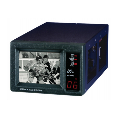
emitor SATLOOK Mark III DiSEqC User manual
emitor
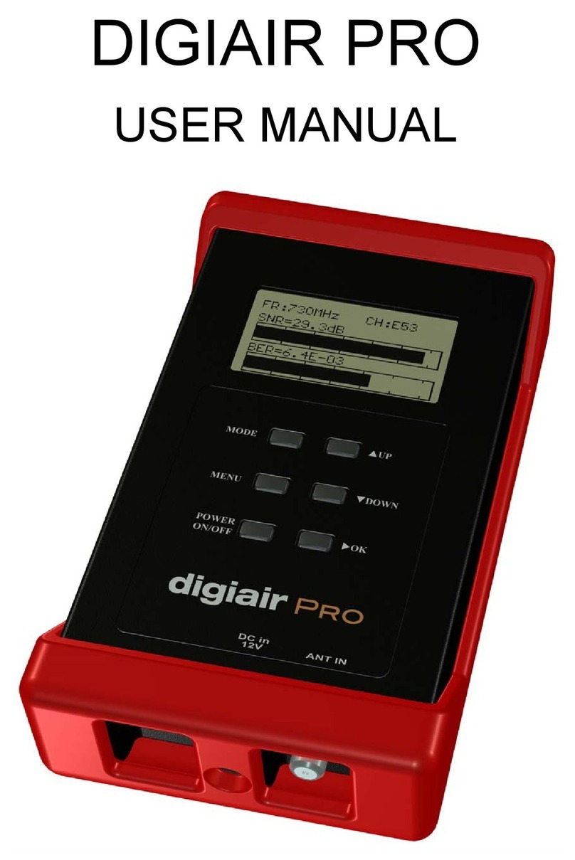
emitor DIGIAIR PRO User manual
emitor
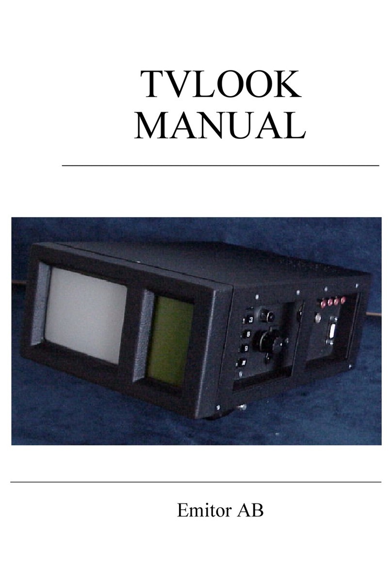
emitor TVLOOK User manual

emitor
emitor COMBOLOOK User manual
emitor
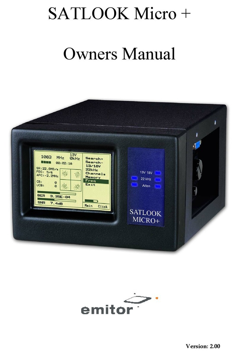
emitor SATLOOK Micro plus User manual
emitor
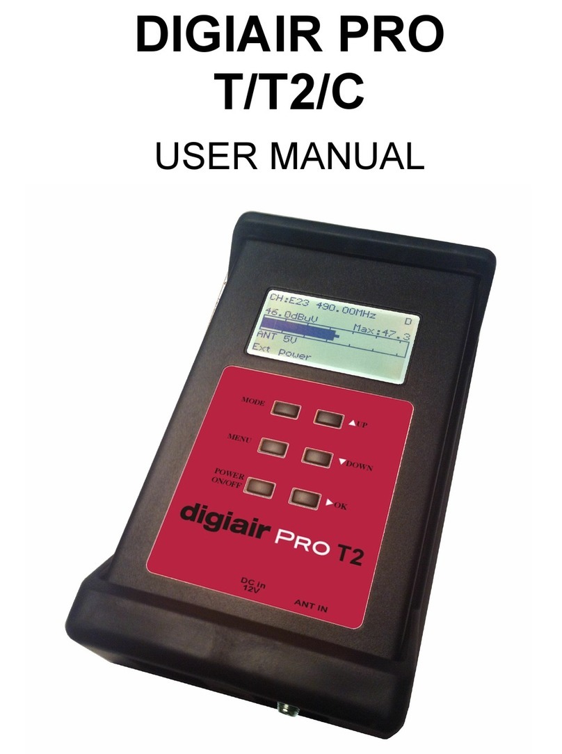
emitor DIGIAIR PRO T User manual
emitor
emitor COMBOLOOK User manual
emitor
emitor satlook Lite User manual
emitor
emitor DIGIAIR User manual
emitor
emitor DIGIAIR PRO CATV User manual
Popular Measuring Instrument manuals by other brands
sauter
sauter FH Series instruction manual

Plott
Plott Cubit user manual
Pilot Communications
Pilot Communications EGO700 Installation & operation manual

Fluke
Fluke 481-DESI Operator's manual

Fluke
Fluke T5-600 Service information

EUTECH INSTRUMENTS
EUTECH INSTRUMENTS CYBERSCAN PC 5000 PHCONDUCTIVITY METER instruction manual


