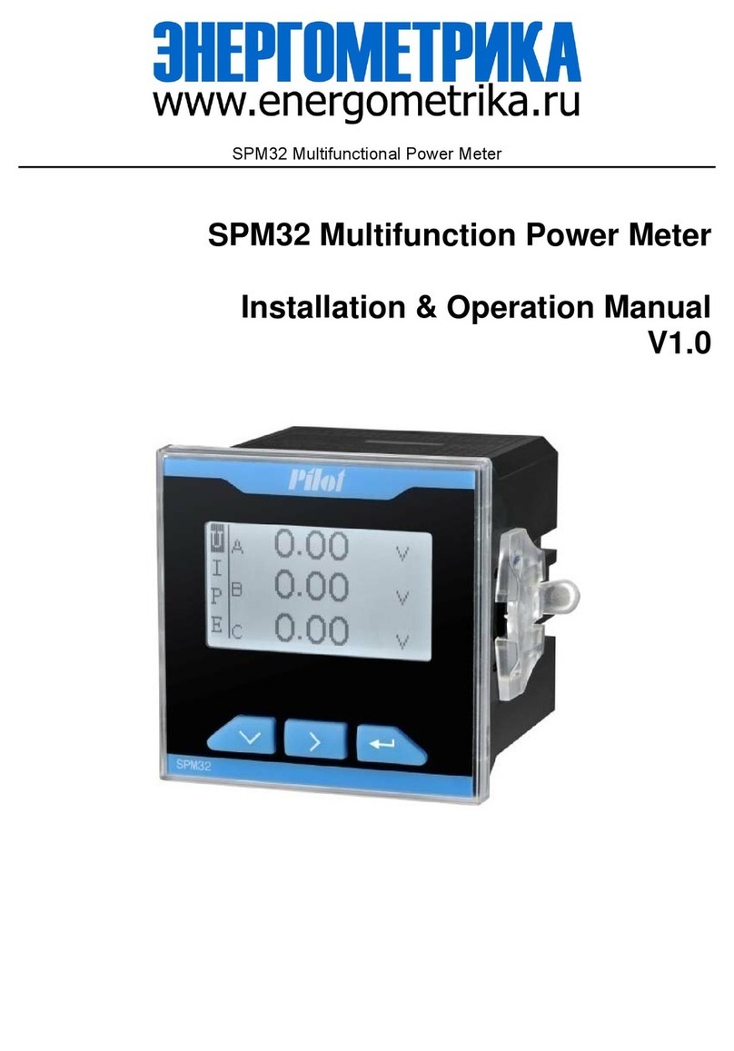
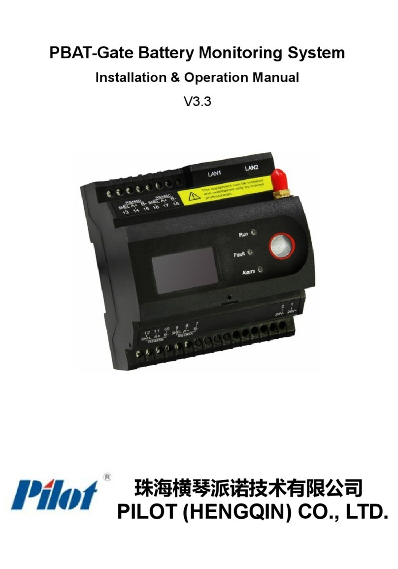
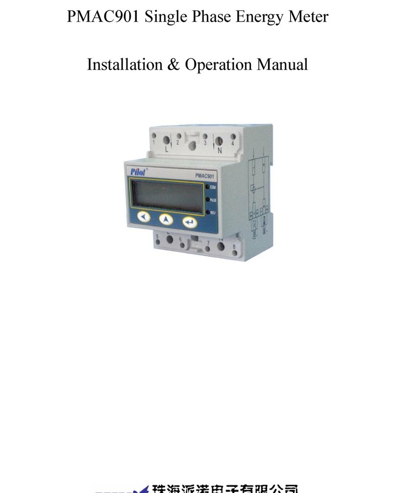
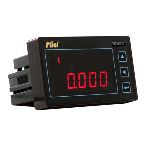
Pilot Communications EGO700 User manual

EGO700 Multi Function Power Meter For
IOT
Installation & Operation Manual
V1.0

Safety Precautions:
General Warnings:
This equipment can only be installed by professionals
The manufacturer will not be responsible for any failure caused by NOT
following the instructions in this manual
Danger Warnings of Electric Shock, Combustion or Explosion:
Equipment can only be installed and maintained by qualified people
Before any operation of the equipment, the voltage input and power supply shall
be isolated and the secondary windings of all CT shall be short circuited
Use a qualified voltage detection device to confirm that the voltage has been cut
off
All mechanical parts, doors and covers shall be returned to their original positions
before powering-on the equipment
The equipment shall be provided with correct rated voltage in use
Failure to pay attention to these precautions may cause serious injury!!

Contents
Chapter 1 Product Overview.......................................................................................... 5
Chapter 2 Product Selection...........................................................................................6
Chapter 3 Dimension......................................................................................................7
3.1 Main part dimensions...........................................................................................................7
3.2 CTC closed current transformer module dimensions..........................................................7
3.3 CTO current transformer dimensions.................................................................................. 8
3.4 Host installation dimensions................................................................................................8
3.5 Host with CTC module installation dimension drawing..................................................... 8
Chapter 4 Display and key operation instructions..........................................................9
4.1 Real-time measurement data display structure....................................................................9
4.2 All show figure...................................................................................................................10
4.3 Button instruction...............................................................................................................10
4.4 Setting parameter description.............................................................................................11
Chapter 5 Measurement performance.......................................................................... 13
5.1 Voltage................................................................................................................................13
5.2 Current................................................................................................................................13
5.3 Frequency...........................................................................................................................14
5.4 Demand parameters............................................................................................................14
5.4.1 Real-time demand........................................................................................................................ 14
5.4.2 Maximum daily demand.............................................................................................................. 15
5.4.3 Maximum monthly demand......................................................................................................... 15
5.5 Electric energy................................................................................................................... 15
5.6 History of electricity energy.............................................................................................. 15
5.7 Harmonic............................................................................................................................15
5.8 Unbalance...........................................................................................................................16
5.9 Fixed value alarm...............................................................................................................16
5.10 Phase sequence adjustment..............................................................................................18
5.10.1 Manual phase sequence adjustment........................................................................................... 18
5.10.2 Automatic phase sequence adjustment.......................................................................................18
Chapter 6 Input-output characteristics......................................................................... 18
6.1 Switch value input..............................................................................................................18
Chapter 7 Technical index............................................................................................ 19
Chapter 8 Maintenance & Troubleshooting................................................................. 21
Chapter 9 Appendix......................................................................................................22
9.1 Terminal diagram............................................................................................................... 22
9.2 Terminal definition table....................................................................................................22
9.3 Terminal specification table...............................................................................................23
9.4 Terminal wiring instructions.............................................................................................. 23
9.4.1 Communications wiring............................................................................................................... 23
9.4.2 Residual current connection.........................................................................................................24
9.4.3 Temperature wiring...................................................................................................................... 24
9.4.4 Switch-volume connection...........................................................................................................25
9.5 Typical wiring diagram...................................................................................................... 25
9.5.1 CTC mode (built-in CT) wiring diagram..................................................................................... 26
9.5.2 External CT wiring diagram.........................................................................................................27

Chapter 1 Product Overview
EGO700 Multi Function Power Meter For IOT is mainly applicable to the
distribution cabinet and switch cabinet in the high and low-voltage distribution system
lower than AC 650kV (phase voltage). It can communicate with RS485 / MODBUS
bus to manage the meter network and realize automatic control.
The product performance fully meets the relevant technical requirements of GB /
T 17215.322-2008 for active power level 0.5s and GB / T 17215.323-2008 for reactive
power level 2.
The product mainly realizes the following functions:
Full power measurement: three phase voltage, current, active power, reactive
power, apparent power, power factor, frequency, voltage and current angle, cable
temperature and residual current
Energy metering: bidirectional electric energy, historical electric energy
Demand function: real time demand, daily maximum demand and monthly
maximum demand
Power quality: 63th harmonic analysis, voltage and current content, THD,
imbalance;
Alarm: over voltage, under voltage, over-current, under current, phase loss,
frequency too high, frequency too low, power too high, switch value 1 off, etc
Data record: historical electric energy for lately 10 years, 12 months and 31 days
Event record of electric parameter maximum value: event record with time scale
and operation record
Communication: 1-way RS485 communication is provided as standard, 4G / Lora
can be selected for infrared communication, MODBUS, HTTP, Mqtt and other
communications are supported, and MODBUS custom register is supported
Switch value input: one active switch input is provided as standard
Temperature of cable: 4-way 0-150 ℃cable temperature measurement
Residual current: 1-way 0-8000ma residual current measurement

Chapter 2 Product Selection
EGO700 -□-□-□
① ② ③
①:Communication mode(required)
RS485
1-way RS485
4G
Lte(4G All netcom)、RS485
LoRa
LoRa、RS485
All
Lte(4G All netcom)、LoRa、RS485
②:Current transformer access(required)
CTO
External 5A/1.67mA open current transformer
CTC
External 5A/1.67mA closed current transformer module
③:Extended function (optional)
T
4-way cable temperature
Note: EGO700 is compatible with 3×57.7/100V and 3×220/380V rated voltage
input.
Example: EGO700-4G-CTO: Three-phase multi-functional power meter
equipped with 1-way active switch quantity input, 4-way cable temperature, 1 channel
residual current, 1-way 4G communication and 1-way RS485 communication external
5A open current transformer access.

Chapter 3 Dimension
3.1 Main part dimensions
Unit:mm
94.00
98.16
63.00 66.00
72.50
Pilot EGO700
Multifunction Power Meter For IOT
电 话 :
400-878-6678
地址 :
Web:
http://www.pmac.com.cn
Zh uh ai Pi lot T ech no lo gy C o., Lt d.
珠海派诺科技股份有限公司
3.2 CTC closed current transformer module dimensions
Unit:mm
87.00
53.00 60.00

3.3 CTO current transformer dimensions
Unit:mm
34.0±0.5
18.4±0.5
28.7±0.5
49.2±0.5
?16.0
31.0±0.5
3.4 Host installation dimensions
Unit:mm
3.5 Host with CTC module installation dimension drawing
Unit:mm

Chapter 4 Display and key operation instructions
4.1 Real-time measurement data display structure
(1) Real-time measurement data shall be displayed in the form of main menu and
sub-menu
(2) Menu tree diagram
①P the main menu by the button

4.2 All show figure
1、Function title;
2、Unit display area;
3、4G signal display icon;
4、The 4G signal strength;
5、Main data display area;
6、Running indicator light: Flashing while running;
7、Network connection light: always on when connected to the Internet;
8、RS485/Lora sending indicator light: flashing when the device sends;
9、RS485/Lora receiving indicator light: flashing when the device receives;
10、Infrared transceiver;
11、Antenna connector.
Note:
If there is no button operation on the homepage in 180s, the screen will be off
and the screen will not be lit again until there is a button pressed. If there is no button
pressed on other pages in 180s, the screen will jump to the homepage.
4.3 Button instruction
In different interfaces, the same button has different functions.
Next key: Change value when switching/programming in peer menu
Enter key: Move the cursor to the left when switching submenus/programming in
the peer menu
Key combination: Ruturn/Switching between real-time pages and programming
pages

4.4 Setting parameter description
■Meter programming
EGO700 can be programmed with the following
parameters:
Programmable item
Meter address
Communication BPS
CT ratio
PT rario
Connection modes
Manual phase sequence
adjustment
Automatic phase
sequence adjustment
Remove power
language
Demo mode
Meter programming needs to verify the password, the
initial password is 01.
1. Meter communication address: Press the combination
key to enter the interface of meter communication
address, as shown in the figure below. Range of
mailing address setting: 1~247
.
2. Communication Baud rate: press the button to enter
the interface of communication Baud rate, as shown in
the figure below. Baud rate can be set: 1200,2400,
4800, 9600, 19200, 38400, 57600.
6. Manual phase sequence adjustment: press the key to
enter the manual phase sequence adjustment interface, as
shown in the figure below
.
7.Automatic phase sequence adjustment: press the
key to enter the interface of automatic phase sequence
adjustment, as shown in the figure below. Select "YES" to
indicate that the phase sequence will be automatically
3. CT ratio: Press the key to enter the CT ratio
interface, as shown in the figure below. Set according
to field CT. CT ratio setting range: 1.00~100000.00
.
4. PT ratio: Press the key to enter the INTERFACE
of PT ratio, as shown in the figure below. Set
according to site PT. Setting range of PT ratio:
1.00~10000.00.
5. Wiring mode: Press the key to enter the wiring
mode interface, as shown in the figure below.
According to the field connection mode, the
connection mode can be set as 3D4Y(three phase four
wire), 3D3Y(three phase three wire).
9Language: Press the key to enter the setting interface
of power clearing, as shown in the figure below. Select
CH for Chinese display and EN for English display.
10.Demo mode: Press the key to enter the demo mode
setting interface, as shown in the figure below. Select
"YES" to turn demo mode on and "NO" to turn demo
mode off.

adjusted, and there will be a corresponding result popup
prompt after the adjustment.
8.Power cleaning: Press the key to enter the setting
interface of power cleaning, as shown in the figure below.
Operation examples
Switch between real-time data page and edit menu:
How to access the Programming menu:
How to modify the voltage PT ratio, after entering programming menu, the
following process into voltage PT ratio the Settings menu:

Chapter 5 Measurement performance
5.1 Voltage
For EGO700 voltage measurement, the maximum direct-connected phase
voltage is 400V, and line voltage is 500V. The user should pay attention to this when
designing to prevent saturation of the internal measurement loop, resulting in
inaccurate measurement and even damage to the meter. Higher voltage needs to be
connected through PT. The meter can set PT ratio, and the maximum measurable
phase voltage on the primary side is 650kV. The voltage connection mode can be set
through the panel or communication, and supports star and delta modes.
5.2 Current
EGO700 must use CT to measure current. The secondary rated output of CT
needs to meet the rated current input requirement of EGO700 (5A). When wiring the
external CT, prevent the CT output from being open, otherwise a higher voltage will
be generated in the secondary under the action of the primary excitation, causing
personal injury or death or equipment damage.
The direct access current of EGO700 current measurement channel is 0~6.5A,
and the theoretical maximum measurement current of CT primary side is 500000A.
The user should pay attention to this point when designing to prevent saturation of the

internal measurement loop, resulting in inaccurate measurement.
5.3 Frequency
When EGO700 works in different measurement modes, the acquisition channels
of frequency measurement are different. In the triangle mode, EGO700 measures
frequency through the AB line voltage channel by default; in other modes, EGO700
measures frequency through the A phase voltage channel. If phase A lacks phase,
phase B is selected. If phase A and phase B are missing, take phase C.
5.4 Demand parameters
5.4.1 Real-time demand
Real-time demand is the value of accumulated electrical parameters divided by
the length of time in a time period.
EGO700 provides two demand calculation modes: fixed mode and slip mode. In
any mode, the demand period can be set (5 minutes, 10 minutes, 15 minutes, 30
minutes, 60 minutes). In the fixed mode, the slip time is meaningless; in the slip mode,
the slip time can be set (1 minute, 2 minutes, 3 minutes, 4 minutes), but it needs to
meet the requirement that "the demand period is 5 of the slip time The relationship of
integer multiple of "is shown in the following table.
EGO700 provides three-phase current, three-phase active power, total active
power demand calculation for a total of 7 electrical parameters, and maximum
demand records. The demand value can be viewed through display or communication,
and the demand maximum value record clearing operation is provided.
The following figure shows the calculation method of the demand fixed mode:
Calculation period (minutes)
Adjustable sliding window size (minutes)
5
1
10
1、2
15
1、3
30
1、2、3
60
1、2、3、4

5.4.2 Maximum daily demand
EGO700 provides the function of the maximum amount needed, can record the
most value of the amount needed on that day, can obtain through communication.
Once the time crosses the day, the maximum daily demand of the previous day will be
cleared 0.
5.4.3 Maximum monthly demand
EGO700 provides month maximum demand function, can record the demand of
that month the most value, can obtain through communication. Once the time crosses
the month, the maximum monthly demand of the last month will be cleared 0.
5.5 Electric energy
The active and reactive input and output power of EGO700 can accumulate up to
99999999.9kWh, and display one decimal place. When the accumulation reaches the
highest value, it will automatically flip.
5.6 History of electricity energy
EGO700 provides the historical electric energy of the latest 31 days, the
historical electric energy of the last 12 months and the historical electric energy of the
latest 10 years. The data saved is the total active electric energy.
5.7 Harmonic
EGO700 can measure the complete 63 times voltage and current harmonics and
their total harmonic content THD, total even harmonic content TEHD and total odd
harmonic TOHD. The harmonic data is given according to the percentage data of the
fundamental wave, with a decimal number, that is, the value of the fundamental wave
is fixed as 1000, which means it accounts for 100.0% of the effective value of the
fundamental wave, and the rest!
Total harmonic content THD refers to the sum of the higher harmonics except the
fundamental wave,press the following formula to calculate
ni
i
i
X
THD
2
2
In the formula:
i
indicates the harmonic order
i
X
indicates the percentage of the effective value of each harmonic
to the effective value of the fundamental wave
n
indicates the highest harmonic order, here should be 63

5.8 Unbalance
In an ideal three-phase power supply system, the ABC three-phase voltage and
current amplitude are equal, and the phase difference is 120°, and it is in a balanced
state at this time. When the actual system deviates from the above situation, the
problem of imbalance and the corresponding reduction of power utilization efficiency
will occur.
EGO700 can measure the positive sequence, negative sequence and zero
sequence amplitude of voltage and current, and calculate and analyze the voltage and
current imbalance.
The voltage and current unbalance calculation formula is as follows:
Voltage unbalance=(Negative sequence component of voltage/Positive sequence
component of voltage)x100%
Current unbalance = (current negative sequence component/current positive sequence
component) x 100%
The zero sequence current
0
I
calculation formula is as follows:
3
)coscoscos()sinsinsin(
0
22 icIcibIbiaIaicIcibIbiaIa
I
In the formula:
Ia stands for A phase current
Ib stands for B phase current
Ic stands for C phase current
ia represents the phase angle of phase A current
ib represents the phase angle of phase B current
ic represents the phase angle of phase C current
5.9 Fixed value alarm
The fixed value alarm parameters of the EGO700 device can be set by the host
computer software through communication. When an alarm event occurs, the alarm
type can be read through communication. There are 22 groups of monitored alarm
objects, and each group of parameters includes the following:
(1) Action mode: on/off.
When this monitoring is enabled, the alarm object will monitor and alarm.
(2) Action value: the action value and return value of the over-limit trigger.
For the upper limit, when the measured value is greater than the action value,
takes action, and when the measured value is less than the action value, returns;
For the lower limit, when the measured value is less than the action value, takes
action,, and when it is greater than the action value, returns;
(3) Action delay time: the time to delay action after the limit is exceeded.
The setting range of the action delay time is 0~120s.
Monitoring and alarm objects include: A-phase voltage upper limit, B-phase
voltage upper limit, C-phase voltage upper limit, A-phase voltage lower limit,

B-phase voltage lower limit, C-phase voltage lower limit, phase loss, A-phase current
upper limit, B-phase current upper limit, C-phase Current upper limit, A phase current
lower limit, B phase current lower limit, C phase current lower limit, total active
power upper limit, frequency upper limit, frequency lower limit, residual current
upper limit, first circuit temperature upper limit, second circuit temperature upper
limit, third circuit temperature upper limit , The fourth circuit temperature upper limit,
DI is disconnected.
When the monitoring object meets the action conditions, it also needs to meet the
time regulation to be truly activated. During the entire delay period, if the monitored
object returns within the limit, the monitoring alarm will not be activated. The unit of
action delay is second, and the value range is 0~120. Setting 0 means that once the
monitored object exceeds the limit, the alarm channel will be activated immediately.
For example: Monitor the upper limit of the A phase voltage and the lower limit
of the A phase voltage at the same time. If the voltage exceeds 120% of the rated
voltage for 5 seconds, an alarm is required, and if the voltage is lower than 80% of the
rated voltage for 3 seconds, an alarm is required. The settings are as follows:
Setting Items
Value
A - phase voltage upper limit action mode
open
A - phase voltage upper limit action value
120
Action time of A phase voltage upper limit
5s
The action mode of A phase voltage lower limit
open
The action value of A phase voltage lower limit
80
A - phase voltage off-line action time
3s
The figure below describes the above and below situations . The rated voltage is
220V, the upper limit is set at 120% of the rated voltage, the upper limit alarm value is
264V, and the lower limit is set at 80% of the rated voltage, and the lower limit is
176V. When the A-phase voltage value continues to be larger than the upper limit 5s,
the alarm is triggered, and the alarm is immediately cancelled when it is lower than
the upper limit. When the A-phase voltage value continues to be lower than the lower
limit 3s, the alarm will be immediately cancelled.

5.10 Phase sequence adjustment
5.10.1 Manual phase sequence adjustment
The user can adjust the phase sequence of the current channel corresponding to
the voltage channel according to the field wiring;
5.10.2 Automatic phase sequence adjustment
The phase sequence can be adjusted automatically by one-key operation through
the meter interface.
[Note] The automatic phase sequence adjustment needs to meet the following
conditions: Under normal working conditions, the wiring mode is three-phase
three-wire mode and the A/B/C three-phase power factor is greater than 0.8;
Chapter 6 Input-output characteristics
6.1 Switch value input
EGO700 comes standard with 1-way active switch value input, which is suitable
for monitoring status information of circuit breaker and switch. External active switch
value.
When the external node is closed, the switch input is displayed as closed, and the
internal state information is set to 1; when the external node is disconnected, the
switch input is displayed as opening, and the internal state information is set to 0.

Chapter 7 Technical index
Parameter
Range
Rated working
parameters
Rated working power supply
AC 85~265V or DC 100~300V
Power consumption
≤ 2W/5VA
Rated input current
CTO:External 5A/1.67mA open current
transformer
CTC:External 5A/1.67mA closed current
transformer module
Rate input voltage
3x220/380V 40Hz~65Hz
Active switch input rated voltage
220V,If it is less than 60V, it is open; if it is
more than 140V, it is closed; the maximum
input is 300V.
Parameter
Range
Accuracy
Accuracy of
electrical
parameters
Direct access voltage
Phase voltage10V~400V
Line voltage10V~500V
0.2%
Primary side voltage
Maximum1000kV
--
Direct access current
5mA~6.5A
0.2%
Primary side current
Maximum 100000A
--
Frequency
40~65Hz
0.1%
Power factor
-1~1
1%
Active energy
0~99999999.9 kWh
0.5%
Reactive energy
0~99999999.9 kvarh
2%
Active power
single phase:
0 ~ ±9999MW/Mvar
total:0 ~ ±9999MW/Mvar
0.5%
Reactive power
1.0%
Unbalance
0%~100%
1%
Harmonic ratio
0%~100%
Level B
Parameter
Performance
Ambient
temperature
Normal working temperature
-20℃~+60℃
Extreme operating temperature
-25℃~+70℃
Storage temperature
-40℃~+85℃
Operating humidity
5%~95%,without condensation

Insulation
performance
Power frequency withstand
voltage
4000VAC(GB/T 17215.211)
Insulation resistance
≥ 100MΩ
Surge voltage
6000V
IP protection
level
Front panel
IP52
Complete machine
IP20
Iterm
Reference standard
Test class
Electromagnetic
Compatibility
ElectroSTatic Discharge
GB/T17626.2-2006
(IEC61000-4-2:2001)
4 level
Radio frequency electromagnetic
field radiation immunity
GB/T17626.3-2006
(IEC61000-4-3:2002)
4 level
Electrical fast transient pulse
group disturbance immunity
GB/T17626.4-2008
(IEC61000-4-4:2006)
4 level
Surge (impact) immunity
GB/T17626.5-2008
(IEC61000-4-5:2005)
4 level
Rf field induction conduction
disturbance immunity
GB/T17626.6-2008
(IEC61000-4-6:2006)
3 level
Electromagnetic emission limit
GB 9254-2008
(CISPR22:2006)
B level
Voltage sag, short interruption
immunity
GB/T17626.11-2008
(IEC61000-4-11:2004)
conform
Table of contents
Other Pilot Communications Measuring Instrument manuals

Pilot Communications
Pilot Communications PMAC735 User manual

Pilot Communications
Pilot Communications PMAC202 User manual

Pilot Communications
Pilot Communications PMAC901 User manual

Pilot Communications
Pilot Communications PM-2104 User manual

Pilot Communications
Pilot Communications PMAC211 User manual

Pilot Communications
Pilot Communications SPM33 User manual

Pilot Communications
Pilot Communications SPM32 User manual

Pilot Communications
Pilot Communications PBAT-Gate User manual

Pilot Communications
Pilot Communications PMAC615 User manual