EMKO ERM-3770 User manual

ERM-3770 77x35 DIN Size Digital Tachometer
- 4 Digits Display
- Adjustable decimal point
- Division rate
- NPN or PNP input type
- Working with Process Set and Alarm Set value
- Alarm output
Relay or SSR driver output (It must be determined in order.)
- Alarm Set value boundary
- 0,07Hz to 10000Hz input signal
- Automatic sampling (1 sec. to 16 sec.)
- Programming mode password protection
ERM-3770 77 x 35 DIN Size
Digital Tachometer
Instruction Manual. ENG ERM-3770 02 V04 09/14

2
ABOUT INSTRUCTION MANUAL
Instruction manual of ERM-3770 Digital Tachometer consists of two main sections.
Explanation of these sections are below. Also, there are other sections which include order
information and technical specifications of the device. All titles and page numbers in instruction
manual are in “ ” section. User can reach to any title with section number.
In this section, physical dimensions of the device, panel mounting, electrical wiring,
physical and electrical installation of the device to the system are explained.
Also in these sections, there are warnings to prevent serious injury while doing the
physical and electrical mounting or using the device.
Explanation of the symbols which are used in these sections are given below.
CONTENTS
Installation:
Operation and Parameters:
In this section user interface of the device, accessing to the parameters, description of the
parameters are explained.
a
c
i
This symbol is used to determine the dangerous situations as a result of an electric
shock. User must pay attention to these warnings definitely.
This symbol is used for safety warnings. User must pay attention to these
warnings.
This symbol is used to determine the important notes about functions and usage of
the device.

1. PREFACE...........................................................................................................................................
2. INSTALLATION...................................................................................................................................
3. ELECTRICAL WIRING.......................................................................................................................
1.1 GENERAL SPECIFICATIONS
1.2 ORDERING INFORMATION
2.1 GENERAL DESCRIPTION
2.4 PANEL CUT-OUT
2.5 ENVIRONMENTAL RATINGS
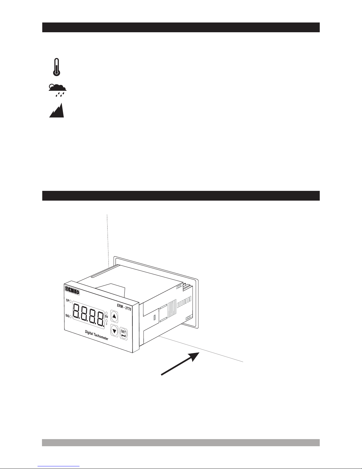
2.6 PANEL MOUNTING
2.7 INSTALLATION FIXING CLAMP
2.8 REMOVING FROM THE PANEL
3.1 TERMINAL LAYOUT AND CONNECTION INSTRUCTIONS
3.4 SUPPLY VOLTAGE INPUT CONNECTION OF THE DEVICE
3.7 ALARM OUTPUT CONNECTIONS
3.7.1 RELAY OUTPUT CONNECTION
1.3 WARRANTY
1.4 MAINTENANCE
2.2 FRONT VIEW AND DIMENSIONS OF ERM-3770 DIGITAL TACHOMETER WITH ALARM
OUTPUT
2.3 FRONT VIEW AND DIMENSIONS OF ERM-3770 DIGITAL TACHOMETER WITHOUT
ALARM OUTPUT
3.2 ELECTRICAL WIRING DIAGRAM
3.3 VIEW OF THE DEVICE LABEL
3.5 PROCESS INPUT CONNECTION
3.5.1 PROXIMITY CONNECTION
3.5.2 SWITCH CONNECTION
3.6 GALVANIC ISOLATION TEST VALUES OF ERM-3770 DIGITAL TACHOMETER
3.7.2 SSR DRIVER OUTPUT CONNECTION
4.1 FRONT PANEL DEFINITION OF ERM-3770 DIGITAL TACHOMETER WITH ALARM
OUTPUT
4.2 FRONT PANEL DEFINITION OF ERM-3770 DIGITAL TACHOMETER WITHOUT ALARM
OUTPUT
4.3 OBSERVATION OF THE SOFTWARE REVISION ON THE DISPLAY
4.4 CHANGING AND SAVING PROCESS SET VALUE
4.5 PROGRAMMING MODE PARAMETER LIST
4.6 OPERATION GRAPHICS OF ALARM OUTPUT AND ALARM TYPES
4.7 EASY ACCESSING DIAGRAM OF PROGRAMMING MODE PARAMETERS
4.7.1 DEVICE WITH ALARM OUTPUT
4.7.2 DEVICE WITHOUT ALARM OUTPUT
4.8 ENTERING TO THE PROGRAMMING MODE, CHANGING AND SAVING PARAMETERS
4. FRONT PANEL DEFINITION AND ACCESSING TO THE MENUS...................................................
5. FAILURE MESSAGES IN ERM 3770 DIGITAL TACHOMETER........................................................
6. SPECIFICATIONS...............................................................................................................................
6.OTHER INFORMATIONS....................................................................................................................
Contents
Page 5
Page 19
Page 12
Page 7
Page 30
3
Page 29
Page 30

4
Manufacturer Company Name :
Manufacturer Company Address:
Emko Elektronik A.S.
DOSAB, Karanfil Sokak, No:6, 16369 Bursa, Turkiye
EU DECLARATION OF CONFORMITY
The manufacturer hereby declares that the product conforms to the following standards and
conditions.
ERM-3770
ERM-3770
Electrical equipment for measurement, control and laboratory
use
Product Name
Model Number :
Type Number :
Product Category :
Conforms to the following directives :
: Digital Tachometer
73 / 23 / EEC The Low Voltage Directive as amended by 93 / 68 / EEC
89 / 336 / EEC The Electromagnetic Compatibility Directive
EN 61000-6-4:2007 EMC Generic Emission Standard for the Industrial Environments
EN 61000-6-2:2005 EMC Generic Immunity Standard for the Industrial Environments
EN 61010-1:2001 Safety Requirements for electrical equipment for measurement, control
And laboratory use
16 October 2009 Name : Serpil YAKIN
Bursa-TURKEY Position : Quality Manager
Has been designed and manufactured to the following specifications :
When and Where Issued Authorized Signature
th

1.Preface
1.1 General Specifications
ERM-3770 series Digital Tachometers are design for measuring the period in Industry. They can
be used in many applications with their easy use, alarm output, universal process input
properties. You can easily adapt them to automation systems and mechanical process.
Some application fields which they are used are below:
Glass
Plastic
Petro-Chemistry
Automotive, Textile
Machine Production Industries
etc.
Period measurement
Frequency measurement
Band Speed measurement
Linear or circular movement
Instantaneous Flow rate
Application Fields
Applications
5
ERM-3770
Optional
Power Supply
Input
Alarm Output
(SSR Driver Output)
Process Input
Alarm Output
Standard
230 V (±%15) , 50/60 HzV
Optional Power Supply
115 V (±%15) , 50/60 HzV
24 V (±%15) , 50/60 HzV
W24 V ( -%15 ; +%10) 50/60 Hz
Optional
Alarm Output
(Relay Output)
Switch
Proximity Sensor
(NPN, PNP)
Optic Sensor

1.2 Ordering Information
6
1.3 Warranty
EMKO Elektronik warrants that the equipment delivered is free from defects in material and
workmanship. This warranty is provided for a period of two years. The warranty period starts from
the delivery date. This warranty is in force if duty and responsibilities which are determined in
warranty document and instruction manual performs by the customer completely.
1.4 Maintenance
Repairs should only be performed by trained and specialized personnel. Cut power to the device
before accessing internal parts.
Do not clean the case with hydrocarbon-based solvents (Petrol, Trichlorethylene etc.). Use of
these solvents can reduce the mechanical reliability of the device. Use a cloth dampened in ethyl
alcohol or water to clean the external plastic case.
All order information of ERM-3770
Digital Tachometer are given on the table at
left. User may form appropriate device
configuration from information and codes
that at the table and convert it to the
ordering codes.
Firstly, supply voltage then other
specifications must be determined. Please
fill the order code blanks according to your
needs.
Please contact us, if your needs are
out of the standards.
V
Z
Vac,
Vdc can be applied.
Þ
Þ
c
Order Information
A BC D E FG HI /
/
UV W Z/
/
0 00 0 0 0
ERM-3770 (77x35 DIN Size)
324 V ( %15) 50/60 HzV±
4115 V ( %15) 50/60 HzV±
5230 V ( %15) 50/60 HzV±
Power Supply
A
1
Alarm Output
E
0None
9Customer
00 00 0
SSR Driver Output (Maximum 28mA,15V )Z
2
Relay Output (Resistive Load 5A@250V , 1NO + 1NC)V
224 V ( -%15 ; +%10) 50/60 HzW

7
In package ,
- One piece unit
- Two pieces mounting clamps
- One piece instruction manual
A visual inspection of this product for possible damage occured during shipment is
recommended before installation. It is your responsibility to ensure that qualified
mechanical and electrical technicians install this product.
If there is danger of serious accident resulting from a failure or defect in this unit, power
off the system and the electrical connection of the device from the system.
The unit is normally supplied without a power supply switch or a fuse. Use power switch
and fuse as required.
Be sure to use the rated power supply voltage to protect the unit against damage and to
prevent failure.
Keep the power off until all of the wiring is completed so that electric shock and trouble
with the unit can be prevented.
Never attempt to disassemble, modify or repair this unit. Tampering with the unit may
results in malfunction, electric shock or fire.
Do not use the unit in combustible or explosive gaseous atmospheres.
During the equipment is putted in hole on the metal panel while mechanical installation
some metal burrs can cause injury on hands, you must be careful.
Montage of the product on a system must be done with it’s fixing clamps. Do not do the
montage of the device with inappropriate fixing clamp. Be sure that device will not fall
while doing the montage.
It is your responsibility if this equipment is used in a manner not specified in this
instruction manual.
separate
Before beginning installation of this product, please read the instruction
manual and warnings below carefully.
2.Installation
c

2.1 General Description
2.2 Front View and Dimensions of ERM-3770 Digital Tachometer With Alarm Output
Mounting Clamp
Front Panel
IP65 protection
NEMA 4X
Panel surface
(maximum thickness 15 mm / 0.59 inch)
8
Maximum 15 0.59 inchmm /
58.5 mm / 2.30 inch4 mm / 0.16 inch
35 mm / 1.38 inch
77 mm / 3.03 inch
Digital Tachometer
SET
ERM - 3770
P
OP
SIG
SV

2.4 Panel Cut-Out
110 mm / 4.33 inch (min)
50 mm / 1.97 inch (min)
29 mm / 1.14 inch
71 mm / 2.79 inch
9
2.3 Front View and Dimensions of ERM-3770 Digital Tachometer Without Alarm Output
Maximum 15 0.59 inchmm /
58.5 mm / 2.30 inch4 mm / 0.16 inch
35 mm / 1.38 inch
77 mm / 3.03 inch
Digital Tachometer
P
ERM - 3770
P
SIG

10
c
Operating Temperature :
Max. Operating Humidity :
Altitude :
0 to 50 °C
90 Rh (non-condensing)
Up to 2000 m.
%
Operating Conditions
Forbidden Conditions:
Corrosive atmosphere
Explosive atmosphere
Home applications (The unit is only for industrial applications)
2.5 Environmental Ratings
c
2.6 Panel Mounting
1-Before mounting the device in your
panel, make sure that the cut-out is the
right size.
2-Insert the device through the cut-out.
If the mounting clamps are on the unit,
put out them before inserting the unit to
the panel.
During installation into a metal panel, care should be taken to avoid injury from
metal burrs which might be present. The equipment can loosen from vibration
and become dislodged if installation parts are not properly tightened. These
precautions for the safety of the person who does the panel mounting.
1
2

11
2.7 Installation Fixing Clamp
1-Pull mounting clamps from left and
right fixing sockets.
2-Pull the unit through the front side of
the panel
The unit is designed for panel
mounting.
1-Insert the unit in the panel cut-out
from the front side.
2- Insert the mounting clamps to the
fixing sockets that located left and
right sides of device and make the unit
completely immobile within the panel
Before starting to remove the unit from panel, power off the unit and the related
system.
Montage of the unit to a system must be done with it’s own fixing clamps. Do not
do the montage of the device with inappropriate fixing clamps. Be sure that
device will not fall while doing the montage.
2.8 Removing from the panel
c
c
2
1
1
2

1 2 3 4 5 6 7 8 9 10 11 12
12
a
3.1 Terminal Layout and Connection Instructions
3.Electrical Wiring
c
c
c
c
You must ensure that the device is correctly configured for your application.
Incorrect configuration could result in damage to the process being controlled,
and/or personal injury. It is your responsibility, as the installer, to ensure that
the configuration is correct.
Device parameters has factory default values. These parameters must be set
according to the system’s needs.
Only qualified personnel and technicians should work on this equipment. This
equipment contains internal circuits with voltage dangerous to human life.
There is severe danger for human life in the case of unauthorized intervention.
Be sure to use the rated power supply voltage to protect the unit against
damage and to prevent failure.
Keep the power off until all of the wiring is completed so that electric shock and
trouble with the unit can be prevented.
Torque
0,5 Nm
Max. 2.5 mm / 0.098 inch
Wire Size:
14 AWG/1 mm²
Solid /Stranded
Screw driver
0,8 x3 mm

13
NOTE-1: The output exist in device withAlarm Output.
i
3.2 Electrical Wiring Diagram
Electrical wiring of the device must be the same as ‘Electrical Wiring Diagram’
below to prevent damage to the process being controlled and personnel injury.
c
a
P/N : 770ERM-3
Yc
OUTPUT
NO NCC
5A@250V V
1 2 3 4 5 6 7 8 9 10 11 12
Power Supply Input
(It must be determined in order.)
230 VA
115 VA
VA
V ( ± %15 ) 50/60 Hz - 1.5
24 V ( ± %15 ) 50/60 Hz - 1.5
24 V ( -%15 ; +%10) 50/60 Hz
V
V
V
W
L N
Relay or SSR
Driver Module Output Sensor Supply Voltage
12 V
Max. 30 mA
Z( ± 35% )
0 V Z
Process Input
(+) (-)
SSR Output
NOTE-1

3.3 View of the Device Label
14
Device Label for Universal Process Input, 230 V Supply Voltage Input
and Relay Output
V
Device Label for Universal Process Input, 230 V Supply Voltage Input Without Alarm
Output
V
2
Y
c
a
LN
OUTPUT
230 V ± 15%
50/60 Hz - 1.5 VA
V
341 5
NO NCC
5 A@250 V V
6 7 8 9 10 11 12
12 V %35
max. 30 mA
Z±
0 VZ
Input
(0,07 Hz - 10 kHz)
P/N : ERM-3770 - 5.00.0.1/00.00/0.0.0.0
2
Y
c
a
LN
230 V ± 15%
50/60 Hz - 1.5 VA
V
341 56 7 8 9 10 11 12
0 VZ
12 V %35
max. 30 mA
Z±
P/N : ERM-3770 - 5.00.0.0/00.00/0.0.0.0
Input
(0,07 Hz - 10 kHz)

15
3.4 Supply Voltage Input Connection of the Device
Supply voltage range must be determined in order. Device is produced
different for low and high voltage. While installing the unit, supply voltage
range must be controlled and appropriate supply voltage must be applied to
the unit. Controlling prevents damages in unit and system and possible
accidents as a result of incorrect supply voltage.
There is no power supply switch or fuse on the device. So the user must put
power supply switch and a fuse to the supply voltage input. In accordance
with the safety regulations, the power supply switch shall bring the
identification of the relevant instrument. Power supply switch and fuse must
be put to a place where user can reach easily.
c
Power supply switch must be two poled for seperating phase and neutral.
On/Off condition of power supply switch is very important in electrical
connection. On/Off condition of power supply switch must be signed for
preventing the wrong connection.
External fuse must be on phase connection in supply input.V
c
c
Make sure that the power supply voltage is the same indicated on the
instrument.
Switch on the power supply only after that all the electrical connections have
been completed.
c
Power Supply Input Connection
4
NL
5
Power
Supply
Switch
c
a
External
Fuse
(1 A T)
Supply Voltage
230 V (± %15) 50/60 Hz or
115 V (± %15) 50/60 Hz or
24 V (± %15) 50/60 Hz or
24 V ( -%15 ; +%10) 50/60 Hz
V
V
V
W
Y
Note-1
Note-1: External Fuse is recommended.

3.5.1 Proximity Connection
3.5 Process Input Connection
16
10 12 11
12 V
Max. 30mA
Z
0 V Z
Input
PROX.
PNP
PNP type operation
=
10 12 11
12 V
Max. 30mA
Z
0 V Z
Input
PROX.
NPN
NPN type operation
=
Sensor Supply Voltage is 12 V %35 maximum 30 mA.Z±
i
3.5.2 Switch Connection
10 12 11
Input
Switch
0 V Z
12 V
Max. 30mA
Z
=
10 12 11
Input
Switch
0 V Z
12 V
Max. 30mA
Z
=
PNP type operation NPN type operation

17
3.6 Galvanic Isolation Test Values of 77ERM-3 0 Digital Tachometer
Power Supply 4
5Ground 12
2000V V
2000V V
2000V V
2000V V
2000 ( ERM-3770 )V for .5
5
V
00V ( for ERM-377 .3 )V0
1
2
Alarm Output
SSR Driver Output
1
2
1
2
Alarm Output
Relay Output
Process
Input 1111
3
1
2
3
2000V V
Voltage Output
12V Z1010

18
3.7.2 SSR Driver Output Connection
Fuse
Load
Last Control
Element
(SSR)
2
Device L N
1
Fuses must be selected according to the application.
c
c
Max.15 V
Max.28 mA
Z
3.7 Alarm Output Connections
Fuses must be selected according to the application.
c
Device
1Load
L N
2
Max
5 A T FuseV
NC
C
NO
3.7.1 Relay Output Connection
3c

Digital Tachometer
SET
ERM - 3770
P
OP
SIG
SV
Display Process Value,
Process Set Value and
Parameters
It is used to enter to
the Process Set Value
Changing Mode,
Programming Mode
and used as Enter
button
It is used to increase the
value in Process Set
Value Changing Mode
and Programming Mode.
Also in programming
mode It is used to access
to the parameter values.
It is used to decrease
the value and Alarm
Cancelling Button
Note-1
Note-1
4. Front Panel Definition and Accessing to the Menus
Alarm Output
Active Led
Led Indication of Process Set Value
Changing Mode is Active
Led Indication of Programming
Mode is Active
Signal Led
19
4.2 Front Panel Definition of ERM-3770 Digital Tachometer Without Alarm Output
4.1 Front Panel Definition of ERM-3770 Digital Tachometer With Alarm Output
Note-1: If increment or decrement button is pressed for 5 seconds continuously, increment and
decrement number become 10, if increment or decrement button is pressed for 10 seconds
continuously, increment and decrement number become 100, if increment or decrement button
is pressed for 15 seconds continuously, increment and decrement number become 1000.
Digital Tachometer
P
ERM - 3770
P
SIG
Display Process Value
and Parameters
It is used to enter to
the Programming
Mode and used as
Enter button
It is used to increase the
value in Programming
Mode. Also in
programming mode It is
used to access to the
parameter values.
It is used to decrease
the value.
Note-1
Note-1
Led Indication of Programming
Mode is Active
Signal Led

20
Main Operation Screen Process Set Value Screen
Change the process set value
with increment and decrement
buttons.
Press SET button for saving the
process set value
SV led lights off and main operation
screen is shown.
If no operation is performed in Process set value changing mode for 20 seconds,
device turns to main operation screen automatically.
i
4.4 Changing and Saving Process Set Value
Main Operation Screen
Process Set Value Screen
When SET button is pressed, SV LED
lights on and process set value is
shown on the display.
SET
P
OP
SIG
SV
SET
P
OP
SIG
SV
SET
P
OP
SIG
SV
SET
P
OP
SIG
SV
Process Set Value changing mode is active, when the device exist Alarm output.
i
When power is first applied to the digital process indicator, software revision number is shown on
the display.
4.3 Observation of Software Revision on the Display
Software
revision
number
Main Operation Screen is shown
“rv” RevisionÞDigital Tachometer
SET
ERM - 3770
P
OP
SIG
SV
Digital Tachometer
SET
ERM - 3770
P
OP
SIG
SV
Table of contents
Other EMKO Measuring Instrument manuals
Popular Measuring Instrument manuals by other brands

B+K precision
B+K precision 309 instruction manual

Challenger Optics
Challenger Optics CO-OPM-48 operating manual

Aquametro
Aquametro AMTRON X-50 Mounting and operating instructions

IKALOGIC
IKALOGIC SP209 Series Datasheet and User Manual

Delta OHM
Delta OHM LP UVA 02 manual

Laser Works
Laser Works LW450SPI operating instructions