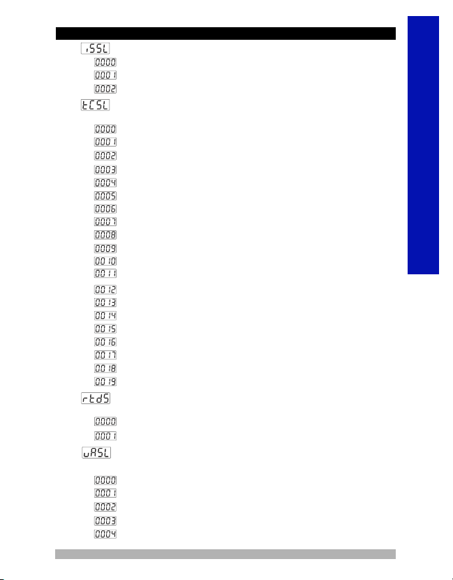
EMKO RS Pro ESM- 00 Series User manual

ESM-XX00 Process Indicator Units
ESM-4400, ESM-7700, ESM-9900, ESM-4900
Universal Input Smart output module system Process
display units
- 4 digit process (PV) display
- Universal process input (TC, RTD, mV Z, V Z, mA Z)
- Dual or multi point calibration for Zvoltage &Zcurrent
inputs
- Smart output module system
- Programmable Alarm functions
- Process control or re-transmission with 0/4...20 mA Z
Current output module
- RS-232 (standart) or RS-485(Optional) serial
communication with Modbus RTU protocol
PROCESS INDICATOR UNITS
ESM-XX00
ENGLISH

ENGLISH
SPECIFICATIONS
PROCESS INPUT
Universal Input: TC, RTD, Z Voltage/Current
Thermocouple (TC): L(DIN 43710) ,J , K , R , S , T , B , E and N
(IEC584.1)(ITS90) ,C (ITS90)
Thermoresistance (RTD): PT-100 (IEC751)(ITS90)
Z Input: mV, V, mA
Measurement Range : Please refer to Table-1 for selection of input
type and scale
Accuracy:± 0.25% of full scale for thermocouple, thermoresistance,
mV, V and mA input.
Cold Junction Compensation:Automatically ±0.1°C/1°C
Line Compensation: Maximum 10 Ohm
Sensor break protection:Upscale
Sampling Cycle:3 samples per second
Input Filter: 0.0 to 900.0 seconds
OUTPUT
Standart Relay Output: 5A@250VV (on resistive load)
Output Modules: User can insert 2 output module to the device.
-Relay Output Module
-SSR Output Module (Max. 26mA , Max. 22V Z)
-Digital (Transistor) Output Module (Max.40 mA @18V Z)
-0/4...20 mA Z Current Output Module
DISPLAY
Process Display :
ESM-4400 : 10.1 mm Red 4 digit LED Display
ESM-4900 : 20.3 mm Red 4 digit LED Display
ESM-7700 : 13.2 mm Red 4 digit LED Display
ESM-9900 : 19 mm Red 4 digit LED Display
LED Göstergeler : °C /°F / V, OP1/2/3 (Output Status) LED.
POWER SUPPLY
Power Supply Voltage :
100-240V V 50/60 Hz (-%15;+%10) -6VA
24V V 50/60 Hz (-%15 ; +%10) -6VA
24V Z (-%15 ; +%10) -6W
(It must be determined in order.)
2

ENGLISH
ENVIRONMENTAL RATINGS and PHYSICAL SPECIFICATIONS
Operating Temperature : 0...50°C
Humidity : 0-90%RH (non condensing)
Protection Class : IP65 at front, IP20 at rear
Mounting : Type-1 Enclosure Mounting
Installation : Fixed installation Category II
Over Voltage Category : II
Pollution Degree : II, office or workplace, none conductive pollution
Weight:
ESM-4400: 210 gr.
ESM-4900: 260 gr.
ESM-7700: 270 gr.
ESM-9900: 360 gr.
Dimensions / Panel Cut-Out:
ESM-4400 : (48 x 48mm, Depth:116 mm) / (46 x 46mm)
ESM-4900 : (96 x 48mm, Depth:86.5 mm) / (92 x 46mm)
ESM-7700 : (72 x 72mm, Depth:87.5 mm) / (69 x 69mm)
ESM-9900 : (96 x 96mm, Depth:87.5 mm) / (92 x 92mm)
Minimum Distance Between Panel Cut-Out Centers:
ESM-4400 : X=65mm, Y=65mm
ESM-4900 : X=129mm, Y=65mm
ESM-7700 : X=97mm, Y=97mm
ESM-9900 : X=129mm, Y=129mm
a
c
i
This symbol is used for safety warnings. User must pay
attention to these warnings.
This symbol is used to determine the dangerous
situations as a result of an electric shock. User must
pay attention to these warnings definitely.
This symbol is used to determine the important notes
about functions and usage of the device
3

ENGLISH
Electrical Wirings
7
24 V Z
Sensor
Supply
Max.50mA
TC
MODULE-1
Output
Module-1
Output
Module-2
MODULE-2
OUTPUT-3
(Alarm or Logic Output)
Universal Process Input
1
8
2
9
3
10
4
11
5
12
6
NO
NC
C
C
5A@250VV
0 to 50 mV Z
0 to 20 mA Z
0 to 10 V Z
Pt-100
CAT II
ESM-4400
Y
c
13
1
14
2
15
3
16
4
17
5
18
6
19
7
20
8
21
9
22
10
23
11
24
12
MODULE - 1
NO C
5A@250VV
24 V Z
Sensor
Supply
Max.50mA
TC
Output Module-1 Output Module-2
OUTPUT-3
(Alarm or Logic Output)
Universal Process Input
0 to 50 mV Z
0 to 20 mA Z
0 to 10 V Z
Pt-100
CAT II
Y
c
ESM-4900
MODULE - 2
NC
Power
Supply
Switch
N L
100...240 VV
50/60 Hz
Power
Supply
Switch
NL
100...240 VV
50/60 Hz
External
Fuse Note-2
(-) (+)
Fuse
Note-1
a
Note-3
Fuse
Note-1
a
External
Fuse
Note-2
(-) (+)
Note-3
4

ENGLISH
10
1
11
2
12
MODULE-1 MODULE-2
3
13
4
14
5
15
6
16
7
17
8
18
9
NCNO C
5A@250VV
24 V Z
Sensor
Supply
Max.50mA
TC
Output
Module-1
Output
Module-2
OUTPUT-3
(Alarm or Logic Output)
Universal Process Input
0 to 50 mV Z
0 to 20 mA Z
0 to 10 V Z
CAT II
ESM-7700
Y
c
Pt-100
100...240 VV
50/60 Hz
13
1
14
2
15
3
16
4
17
5
18
6
19
7
20
8
21
9
22
10
23
11
24
12
NC
MODULE - 1 MODULE - 2
NO C
5A@250VV
24 V Z
Sensor
Supply
Max.50mA
TC
Output Module-1 Output Module-2
OUTPUT-3
( Alarm or Logic Output)
0 to 50 mV Z
0 to 20 mA Z
0 to 10 V Z
Pt-100
Universal Process Input
CAT II
Y
c
ESM-9900
Power
Supply
Switch
100...240 VV
50/60 Hz
Power
Supply
Switch
Fuse
Note-1
a
External
Fuse
Note-2
NL
(-) (+)
Note-3
Fuse
Note-1
a
External
Fuse
Note-2
NL
(-) (+)
Note-3
Note-1 :There is an internal fusible flameproof resistor.
1AVT for power supply 240 VV or 24VV
1AZT for power supply 24V Z
Note-3 : “L” is ( + ) ,” N” is ( - ) for 24V Z supply voltage
Note-2 : External fuse is recommended.
100...
5

ENGLISH
DIMENSIONS
48 mm / 1.89 inch
48mm / 1.89 inch
104.5 mm/ 4.11 inch
Maximum 5mm / 0.2 inch
11.5 ± 1 mm /0.45 inch
°C
°F
V
OP1
OP2
OP3
SET
ESM-4400
Process Indicator
Maximum 15mm / 0.59 inch
48mm/ 1.89 inch
96mm / 3.78 inch
76mm / 2.99 inch
10.5 ± 1 mm /0.41 inch
°C
°F
O1
O2
O3
V
Process Indicator ESM - 4900
PSET
Maximum 15mm / 0.59 inch
72mm / 2.83 inch
72mm / 2.83 inch
76mm / 2.99 inch
11.5 ± 1 mm /0.45 inch
°C
°F
V
OP1
OP2
OP3
Process Indicator
ESM-7700
SET
Maximum 15mm / 0.59 inch
96mm / 3.78 inch
96mm / 3.78 inch
76mm / 2.99 inch11.5 ± 1 mm /0.45 inch
°C
°F
V
OP1
OP2
OP3
Process Indicator
ESM-9900
SET
6

PANEL MOUNTING
4-Insert the unit in the panel
cut-out from the front side.
5- Insert the mounting clamps
to the holes that located top
and bottom sides of device
and screw up the fixing
screws until the unit
completely immobile within
the panel
4
5
1
2
3
1-Before mounting the device
in your panel, make sure that
the cut-out is of the right size.
2-Check front panel gasket
position.
3-Insert the device through the
cut-out. If the mounting clamps
are on the unit, put out them
before inserting the unit to the
panel.
2
3
1
7
ENGLISH

8
Press SET
Button
Press
Increment
button to
enter Alarm-1
set value.
Press SET
button to
save the
Alarm-1 Set
value.
Main Screen Alarm-1 Set Screen
°C
°F
V
OP1
OP2
OP3
SET
°C
°F
V
OP1
OP2
OP3
SET
°C
°F
V
OP1
OP2
OP3
SET
°C
°F
V
OP1
OP2
OP3
SET
Alarm-2 Set Screen
°C
°F
V
OP1
OP2
OP3
SET
°C
°F
V
OP1
OP2
OP3
SET
°C
°F
V
OP1
OP2
OP3
SET
Alarm-3 Set Screen
°C
°F
V
OP1
OP2
OP3
SET
°C
°F
V
OP1
OP2
OP3
SET
°C
°F
V
OP1
OP2
OP3
SET
°C
°F
V
OP1
OP2
OP3
SET
Main Screen
Press increment
or decrement
button to change
the Alarm-1 Set
Value.
Press
Increment
button to
enter Alarm-2
set value.
Press
Increment
button to
enter Alarm-3
set value.
P
Press SET
button to
save the
Alarm-2 Set
value.
Press increment
or decrement
button to change
the Alarm-2 Set
Value.
Press SET
button to
save the
Alarm-3 Set
value.
Press increment
or decrement
button to change
the Alarm-3 Set
Value.
Access and change Set values
Note: User can exit from Set Value section without saving the values by pressing button.
If no operation for 120 seconds, device automatically exits from Set Value section .
ENGLISH

Note: For detailed information look PASS ConF
section.
°C
°F
V
OP1
OP2
OP3
SET
°C
°F
V
OP1
OP2
OP3
SET
SET
SET
SET
SET
SET
SET
SET
SET
SET
SET
SET
SET
°C
°F
V
OP1
OP2
OP3
°C
°F
V
OP1
OP2
OP3
SET
°C
°F
V
OP1
OP2
OP3
°C
°F
V
OP1
OP2
OP3
SET
SET
SET
°C
°F
V
OP1
OP2
OP3
°C
°F
V
OP1
OP2
OP3
SET
SET
SET
SET
SET
°C
°F
V
OP1
OP2
OP3
°C
°F
V
OP1
OP2
OP3
SET
SET
SET
SET
SET
SET
SET
SET
°C
°F
V
OP1
OP2
OP3
°C
°F
V
OP1
OP2
OP3
SET
SET
SET
SET
SET
SET
SET
°C
°F
V
OP1
OP2
OP3
°C
°F
V
OP1
OP2
OP3
SET
°C
°F
V
OP1
OP2
OP3
SET
°C
°F
V
OP1
OP2
OP3
°C
°F
V
OP1
OP2
OP3
°C
°F
V
OP1
OP2
OP3
SET
Main Screen
°C
°F
V
OP1
OP2
OP3
SET
Technician menu
entering screen
Technician password
entering screen
Press Menu
Button.
Press Set/OK Button
to enter password
entering screen.
Press Increment button
to access password
entering screen
Enter password with
using Increment or
decrement buttons.
Press Set/OK Button
to approve password.
NOTE1: If there is EMO-X00, EMO-X10, EMO-X20
output module in MODULE-1 socket, these
parameters are shown.
NOTE1 NOTE2
NOTE3 NOTE4
NOTE3: If there is EMO-X30 module in MODULE-1
socket, this parameter is shown.
NOTE4:
socket, this parameter is shown.
If there is EMO-X30 module in MODULE-2
NOTE2:
output module in MODULE-2 socket, these
parameters are shown.
If there is EMO-X00, EMO-X10, EMO-X20
Technician password
entering screen
Easy Access diagram of Program Parameters
9
ENGLISH

Process Input Type
TC input type selection
RTD input type selection
ZVoltage / Current input type selection.
TC Input Selection
This parameter is active if TC input type is selected.
L (-100°C;850°C) or (-148°F;1562°F)
L (-100.0°C;850.0°C) or (-148.0°F;999.9°F)
J (-200°C;900°C) or (-328°F;1652°F)
J (-199.9°C;900.0°C) or (-199.9°F;999.9°F)
K (-200°C;1300°C) or (-328°F;2372°F)
K (-199.9°C;999.9°C) or (-199.9°F;999.9°F)
R (0°C;1700°C) or (32°F;3092°F)
R (0.0°C;999.9°C) or (32.0°F;999.9°F)
S (0°C;1700°C) or (32°F;3092°F)
S (0.0°C;999.9°C) or (32.0°F;999.9°F)
T (-200°C;400°C) or (-328°F;752°F)
T (-199.9°C;400.0°C) or (-199.9°F;752.0°F)
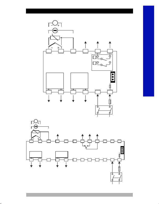
PınP ConF: Process Input Type and Relevant Parameters
B (44°C;1800°C) or (111°F;3272°F)
B (44.0°C;999.9°C) or (111.0°F ; 999.9°F)
E (-150°C;700°C) or (-238°F;1292°F)
E (-150.0°C;700.0°C) or (-199.9°F;999.9°F)
N (-200°C;1300°C) or (-328°F;2372°F)
N (-199.9°C;999.9°C) or (-199.9°F;999.9°F)
C (0°C;2300°C) or (32°F;3261°F)
C (0.0°C;999.9°C) or (32.0°F;999.9°F)
RTD Input Selection
This parameter is active if RTD input is selected.
PT-100 ( -200°C ; 650°C ) or ( -328°F ; 1202°F)
PT-100 ( -199.9°C ; 650.0°C ) or ( -199.9°F ;999.9°F)
Zvoltage / Current Input Selection
This parameter is active if ZVoltage / Current is selected.
0...50mV Z ( -1999 ; 9999 )
0...5V Z ( -1999 ; 9999 )
0...10V Z ( -1999 ; 9999 )
0...20mA Z ( -1999 ; 9999 )
4...20mA Z ( -1999 ; 9999 )
10
ENGLISH

ENGLISH
No point
Fixed dual point display adjustment. Display adjustment low
point value is fixed to -1999, display adjustment high point
value is fixed to 9999.
Between second and third digits “0.00”
User can do defined 16 display adjustment points.
Between third and fourth digits “0.000”
Between first and second digits “0.0”
User can do dual point display adjustment with tPoL and tPoH.
Display Point Position
This parameter is active if oltage/Current input is selected.ZV
Display Value Adjustment Type
This parameter is active if oltage/Current input is selected.ZV
Low Point Display adjustment (-1999, 9999)Unit
This parameter is active if oltage/Current input is selected.ZV
High Point Display adjustment (-1999, 9999)Unit
This parameter is active if oltage/Current input is selected.ZV
Display adjustment points (-1999, 9999)Unit
This parameter is active if oltage/Current input is selected.
In multi point display adjustment operation, defined scale is
divided into 16 adjustment points.
For example : is (0-50 mV ) .
ZV
Z
mV Z
50
Po00 = 0
Po01
Po02
Po03
Po04
Po05
Po16
Po06
Po15
Po07
Po08
Po09
Po10
3.125 3.125 3.125 3.125 3.125 3.125 3.125 3.125 3.125 3.125 3.125 3.125 3.125 3.125 3.125 3.125
3.125 6.25 9.375 12.5 15.625 18.75 21.825 25 28.125 31.25 34.375 37.5 40.625 43.75 46.875
Po14
Po13
Po12
Po11
Process
Set value
0-50 mVZ range are divided into 16 egual parts. Every “Poxx” SET value is defined
50 / 16 = 3.125 mVZ range.
11

ENGLISH
Unit selection
Unit is °C
Unit is °F
Operating Scale Minimum Value
(Scale Low Point, Scale High Point)Unit
Used for Proportional band calculation and display blink.
Unit is Voltage. This selection is active if ZVoltage/Current
input is selected
No unit. This selection is active if oltage / current input is
selected
ZV
Coefficient value (1.000, 9.999)
Process value is multiplied with this value.
ZVThis parameter is active if oltage/Current input is selected.
Operating Scale Maximum Value
(Scale Low Point, Scale High Point)Unit
Used for Proportional band calculation and display blink.
Display offset for process value (Scale -10%, Scale
+10%)Unit
This parameter value is added to the process value.
Filter Time (0.0, 900.0)Second
Defines filter time for display value.
Cold Junction Compensation
This parameter is active if process input is selected TC input.
Cold junction compensation is active.
Cold junction compensation is not active.
Scale: The difference, between high point and low point of the process
input type. Example: If tCSL = 2 (low point is -200, high point is 900),
then scale is 1100. If input type is Voltage/Current, then the scale is
difference between tPoH and tPoL parameters.
12

ENGLISH
MODULE-1 alarm type. This parameter is active, if the Logic-
1 output function is Alarm output.
Process high alarm
Process low alarm
This parameter is active, if the Logic-1 output function is
Alarm output.
Alarm-1 On delay time (0, 9999)Second
This parameter is active, if the Logic-1 output function is
Alarm output.
Alarm-1 Type
Alarm-1 hysteresis value (0% of scale, 50% of scale)Unit
Alarm output
Sensor break alarm output
MODULE-1 output module Logic output function
If there is EMO-X00 (Relay Output) , EMO-X10 (SSR driver)
and EMO-X20 (Digital Output) module in MODULE-1
socket, then the following parameters is active.
i
If there is EMO-X30 ( )
module in MODULE-1 socket, then the following
parameter is active.
0/4...20 mA Z Current output
i
MODULE-1 analogue output module configuration
0...20mAZ output 4...20mAZ output
Scale
0 20
mA
UPL
LOL
Re-transmission
Output is active when the process value is out of the band
which is defined with minimum value of operating scale
and maximum value of operating scale
Alarm-1 Off Delay Time (0, 9998)
When the value is greater than 9998, is seen on the
screen. It means alarm latching output is selected.
if logic-1 output function of Alarm-1
Output is alarm output.
Second
This
parameter is active
Scale
0 20
mA
UPL
LOL
Re-transmission
4
out1 ConF: MODULE-1 parameters
13

ENGLISH
MODULE-2 alarm type. This parameter is active, if the Logic-
2 output function is Alarm output.
Process high alarm
Process low alarm
This parameter is active, if the Logic-2 output function is
Alarm output.
Alarm-2 On delay time (0, 9999)Second
This parameter is active, if the Logic-2 output function is
Alarm output.
Alarm-2 Type
Alarm-2 hysteresis value (0% of scale, 50% of scale)Unit
Alarm output
Sensor break alarm output
MODULE-2 output module Logic output function
If there is EMO-X00 (Relay Output) , EMO-X10 (SSR driver)
and EMO-X20 (Digital Output) module in MODULE-2
socket, then the following parameters is active.
i
Output is active when the process value is out of the band
which is defined with minimum value of operating scale
and maximum value of operating scale
Alarm-2 Off Delay Time (0, 9998)
When the value is greater than 9998, is seen on the
screen. It means alarm latching output is selected. This
parameter is active if logic-2 output function of Alarm-2
Output is alarm output.
Second
out2 ConF: MODULE-2 parameters
If there is EMO-X30 ( )
module in MODULE-2 socket, then the following
parameter is active.
0/4...20 mA Z Current output
i
MODULE-2 analogue output module configuration
0...20mAZ output 4...20mAZ output
Scale
0 20
mA
UPL
LOL
Re-transmission Scale
0 20
mA
UPL
LOL
Re-transmission
4
out2 ConF: MODULE-2 parameters
14

ENGLISH
Alarm output
Sensor break alarm output
Output-3 Logic output function
Process High Alarm
HYS
ON
OFF
Alarm
Set
Alarm
Output
Process Value
Process Low Alarm
HYS
ON
OFF
Alarm
Set
Alarm
Output
Process Value
Process high alarm
Process low alarm
This parameter is active, if the Logic-3 output function is
Alarm output.
Alarm-3 On delay time (0, 9999)Second
This parameter is active, if the Logic-3 output function is
Alarm output.
Alarm-3 Type
Alarm-3 hysteresis value (0% of scale, 50% of scale)Unit
Output is active when the process value is out of the band
which is defined with minimum value of operating scale
and maximum value of operating scale
Alarm-3 Off Delay Time (0, 9998)
When the value is greater than 9998, is seen on the
screen. It means alarm latching output is selected. This
parameter is active if logic-3 output function of Alarm-3
Output is alarm output.
Second
out3 ConF: MODULE-3 parameters
Alarm Types
15

ENGLISH
Alarm Set value Low limit ( , )Unit
Alarm Set ( , )Unitvalue High limit
Process High Alarm
HYS
ON
OFF
Alarm
Set
Alarm
Output
Process Value
Process Low Alarm
HYS
ON
OFF
Alarm
Set
Alarm
Output
Process Value
Communication Accessing Address (1,247)
Communication accessing address of device.
Communication accessing address can be adjusted from 1
to 247.
Communication Baud Rate
1200 Baud Rate.
2400 Baud Rate .
4800 Baud Rate
9600 Baud Rate
19200 Baud Rate
Parity Selection for Communication
No parity.
Odd parity.
Even parity.
Alarm Types
Gen ConF: General Parameters
Com ConF: Serial Communication Configuration Parameters
Stop Bit Selection for Communication
1 stop bit
2 stop bit
16
ENGLISH

°C
°F
V
OP1
OP2
OP3
SET
°C
°F
V
OP1
OP2
OP3
SET
1 - Sensor failure in analogue inputs.
Sensor connection is wrong or there is no
sensor connection.
2- If top display blinks : If analogue input
value is less than minimum value of
operating scale top display starts to
blink.
3- If top display blinks : If analogue input
value is greater than maximum value of
operating scale top display starts to
blink.
4- If technician password is different from “0” and user accesses
to the parameter by Set button without entering the technician
password and wants to change a parameter, the warning
message is shown on the display as shown on the right.
Device does not allow to do any changes without entering the
password correctly.
SET
°C
°F
V
OP1
OP2
OP3
SET
°C
°F
V
OP1
OP2
OP3
SET
°C
°F
V
OP1
OP2
OP3
ESM-XX00 Process Control Unit Error Messages
17
ENGLISH
ENGLISH

c
If there is danger of serious accident resulting from a failure or defect in
this unit, power off the system and separate the electrical connection
of the device from the system.
The unit is normally supplied without a power switch or a fuse. Use
power switch and fuse as required.
Be sure to use the rated power supply voltage to protect the unit
against damage and to prevent failure.
Keep the power off until all of the wiring is completed so that electric
shock and trouble with the unit can be prevented.
Never attempt to disassemble, modify or repair this unit. Tampering
with the unit may results in malfunction, electric shock or fire.
Do not use the unit in combustible or explosive gaseous atmospheres.
During the equipment is putted in hole on the metal panel while
mechanical installation some metal burrs can cause injury on hands,
you must be careful.
Montage of the product on a system must be done with it’s mounting
clamp. Do not do the montage of the device with inappropriate
mounting clamp. Be sure that device will not fall while doing the
montage.
It is your responsibility if this equipment is used in a manner not
specified in this instruction manual.
Before beginning installation of this product, please
read the instruction manual and warnings below
carefully.
In package ,
- One piece unit
- Two pieces mounting clamp
- One piece instruction manual
A visual inspection of this product for possible damage occured during
shipment is recommended before installation. It is your responsibility
to ensure that qualified mechanical and electrical technicians install
this product.
Installation
18
ENGLISH

ENGLISH
Manufacturer Information:
Emko Elektronik Sanayi ve Ticaret A.Ş.
Demirtaş Organize Sanayi Bölgesi Karanfil Sk. No:6 16369
BURSA /TURKEY
Phone : +90 224 261 1900
Fax : +90 224 261 1912
Repair and Maintenance Service Information:
Emko Elektronik Sanayi ve Ticaret A.Ş.
Demirtaş Organize Sanayi Bölgesi Karanfil Sk. No:6 16369
BURSA /TURKEY
Phone : +90 224 261 1900
Fax : +90 224 261 1912
EMKO Elektronik warrants that the equipment delivered is free from
defects in material and workmanship. This warranty is provided for a
period of two years. The warranty period starts from the delivery date.
This warranty is in force if duty and responsibilities which are
determined in warranty document and instruction manual performs by
the customer completely.
Repairs should only be performed by trained and specialized
personnel. Cut power to the device before accessing internal parts.
Do not clean the case with hydrocarbon-based solvents (Petrol,
Trichlorethylene etc.). Use of these solvents can reduce the
mechanical reliability of the device. Use a cloth dampened in ethyl
alcohol or water to clean the external plastic case.
Warranty
Maintenance
Other Informations
Warranty
Warranty
Maintenance
Maintenance
Warranty
Other Informations
19

ESM-9900 (96x96 DIN 1/4)
ESM-4400 (48x48 DIN 1/16)
ESM-7700 (72x72 DIN Size)
Supply Voltage
A
A
1
2
BC D E FG HI /
/
U V W Z/
/
ESM-4900 (96x48 DIN 1/8)
100-240V V (-%15;+%10) 50/60Hz
24V V (-%15;+%10) 50/60Hz 24V Z (-%15;+%10)
Customer (Maximum 240V V (-%15;+%10))50/60Hz
9
0 0 0 0
1
0
1
2
None
RS-232
RS-485
Serial CommunicationD
20 Configurable(Table-1) Table-1
Input type ScaleBC
1Relay Output(5A@250VV on resistive Load)
Output-3
E
00
01
02
03
04
None
Relay Output Module
SSR driver Output Module
Digital (Transistor) Output Module
Current Output Module
Module-1
FG
EMO-400,EMO-700,EMO-900
EMO-410,EMO-710,EMO-910
EMO-420,EMO-720,EMO-920
EMO-430,EMO-730,EMO-930
Module Codes
(Maximum 26mA, 22V Z)
(Maximum 40mA@18V Z)
(0/4...20 mA Z veya 0...10V Z)
00
01
02
03
04
None
Relay Output Module
SSR driver Output Module
Digital (Transistor) Output Module
Current Output Module
EMO-400,EMO-700,EMO-900
EMO-410,EMO-710,EMO-910
EMO-420,EMO-720,EMO-920
EMO-430,EMO-730,EMO-930
Module Codes
(Maximum 26mA, 22V Z)
(Maximum 40mA@18V Z)
(0/4...20 mA Z veya 0...10V Z)
Module-2
HI
Product Code
EMC-400,EMC-700,EMC-900
EMC-410,EMC-710,EMC-910
Ordering Information
20
ENGLISH
This manual suits for next models
4
Table of contents
Languages:
Other EMKO Measuring Instrument manuals
Popular Measuring Instrument manuals by other brands

Delmhorst
Delmhorst F-2000T Operation manual

Extech Instruments
Extech Instruments RC100 user guide

Ludlum Measurements
Ludlum Measurements 12SA manual

Optical dimensions
Optical dimensions Lasercheck 6212C Operations and Specification Manual

Oakton
Oakton T-100IR instruction manual

Compass
Compass 238 210 instruction manual