manuals.online logo
Brands
  1. Home
  2. •
  3. Brands
  4. •
  5. Ross
  6. •
  7. Recording Equipment
  8. •
  9. Ross softGear User manual

Ross softGear User manual

Broadcast Audio Processor User Guide
Thank You for Choosing Ross
You've made a great choice. We expect you will be very happy with your purchase of Ross
Technology.
Our mission is to:
1. Provide a Superior Customer Experience
• offer the best product quality and support
2. Make Cool Practical Technology
• develop great products that customers love
Ross has become well known for the Ross Video Code of Ethics. It guides our interactions and
empowers our employees. I hope you enjoy reading it below.
If anything at all with your Ross experience does not live up to your expectations be sure to reach
out to us at solutions@rossvideo.com.
David Ross
CEO, Ross Video
[email protected]
Ross Video Code of Ethics
Any company is the sum total of the people that make things happen. At Ross, our employees are a
special group. Our employees truly care about doing a great job and delivering a high quality
customer experience every day. This code of ethics hangs on the wall of all Ross Video locations to
guide our behavior:
1. We will always act in our customers’ best interest.
2. We will do our best to understand our customers’ requirements.
3. We will not ship crap.
4. We will be great to work with.
5. We will do something extra for our customers, as an apology, when something big goes wrong
and it's our fault.
6. We will keep our promises.
7. We will treat the competition with respect.
8. We will cooperate with and help other friendly companies.
9. We will go above and beyond in times of crisis. If there's no one to authorize the required action in
times of company or customer crisis - do what you know in your heart is right. (You may rent
helicopters if necessary.)
BAP · User Guide
• Ross Part Number: 3900DR-404-01
• Release Date: April 5, 2021.
The information contained in this Guide is subject to change without notice or obligation.
Copyright
©2021 Ross Video Limited, Ross®, and any related marks are trademarks or registered trademarks
of Ross Video Limited. All other trademarks are the property of their respective companies.
PATENTS ISSUED and PENDING. All rights reserved. No part of this publication may be reproduced,
stored in a retrieval system, or transmitted in any form or by any means, mechanical, photocopying,
recording or otherwise, without the prior written permission of Ross Video. While every precaution
has been taken in the preparation of this document, Ross Video assumes no responsibility for
errors or omissions. Neither is any liability assumed for damages resulting from the use of the
information contained herein.
©2021 The Nielsen Company. All rights reserved.
Trademarks
Manufactured under license from Dolby Laboratories. Dolby, Dolby Audio, and the double-D
symbol are trademarks of Dolby Laboratories Licensing Corporation.
Patents
Patent numbers US 7,034,886; US 7,508,455; US 7,602,446; US 7,802,802 B2; US 7,834,886; US
7,914,332; US 8,307,284; US 8,407,374 B2; US 8,499,019 B2; US 8,519,949 B2; US 8,743,292 B2; GB
2,419,119 B; GB 2,447,380 B; and other patents pending.
Notice
The material in this manual is furnished for informational use only. It is subject to change without
notice and should not be construed as commitment by Ross Video Limited. Ross Video Limited
assumes no responsibility or liability for errors or inaccuracies that may appear in this manual.
Safety Notices
Refer to the “Important Regulatory and Safety Notices” document that accompanied your
product.
EMC Notices
US FCC Part 15
This equipment has been tested and found to comply with the limits for a class A Digital device,
pursuant to part 15 of the FCC Rules.
These limits are designed to provide reasonable protection against harmful interference when the
equipment is operated in a Commercial environment. This equipment generates, uses, and can
radiate radio frequency energy and, if not installed and used in accordance with the instruction
manual, may cause harmful interference to radio communications. Operation of this equipment in
a residential area is likely to cause harmful interference in which case the user will be required to
correct the interference at his own expense.
Canada
This Class “A” digital apparatus complies with Canadian ICES-003 and part 15 of the FCC Rules.
Cet appareil numerique de la classe “A” est conforme a la norme NMB-003 du Canada.
European Union
This equipment is in compliance with the essential requirements and other relevant provisions
established under regulation (EC) No 765/2008 and Decision No 768/2008/EC referred to as the
“New Legislative Framework”.
Australia/New Zealand
This equipment is in compliance with the provisions established under the Radiocommunications
Act 1992 and Radiocommunications Labeling (Electromagnetic Compatibility) Notice 2008.
International
This equipment has been tested under the requirements of CISPR 22:2008 or CISPR 32:2015 and
found to comply with the limits for a Class A Digital device.
Maintenance/User Serviceable Parts
Routine maintenance to this product is not required. This product contains no user serviceable
parts. If the module does not appear to be working properly, please contact Technical Support
using the numbers listed under the “Contact Us” section of this manual. All openGear products are
covered by a generous 3-year warranty and will be repaired without charge for materials or labor
within this period. See the “Warranty and Repair Policy” section in this manual for details.
Environmental Information
The equipment may contain hazardous substances that could impact health and the environment.
To avoid the potential release of those substances into the environment and to diminish the need
for the extraction of natural resources, Ross Video encourages you to use the appropriate take-back
systems. These systems will reuse or recycle most of the materials from your end-of-life equipment
in an environmentally friendly and health conscious manner.
The crossed-out wheeled bin symbol invites you to use these systems.
Notice — Changes or modifications to this equipment not expressly approved by Ross Video Ltd. could
void the user’s authority to operate this equipment.
Warning — This equipment is compliant with Class A of CISPR 32. In a residential environment this
equipment may cause radio interference.
Notice — This is a Class A product. In domestic environments, this product may cause radio
interference, in which case the user may have to take adequate measures.
If you need more information on the collection, reuse, and recycling systems, please contact your
local or regional waste administration. You can also contact Ross Video for more information on the
environmental performances of our products.
Company Address
Ross Video Limited
8 John Street
Iroquois, Ontario
Canada, K0E 1K0
Ross Video Incorporated
P.O. Box 880
Ogdensburg, New York
USA 13669-0880
General Business Office: (+1) 613  652  4886
Fax: (+1) 613  652  4425
Technical Support: (+1) 613  652  4886
After Hours Emergency: (+1) 613  349  0006
E-mail (Technical Support): [email protected]
E-mail (General Information): [email protected]
Website: http://www.rossvideo.com
BAP User Guide (v1.0) Contents • i
Contents
Introduction 11
Related Publications ................................................................................................................................ 11
Documentation Conventions .................................................................................................................. 11
Interface Elements ................................................................................................................................. 12
User Entered Text .................................................................................................................................. 12
Referenced Guides ................................................................................................................................ 12
Menu Sequences ................................................................................................................................... 12
Important Instructions .......................................................................................................................... 12
Contacting Ross Video Technical Support ............................................................................................. 12
Contacting the Nielsen Encoder Support Group .................................................................................. 12
Before You Begin 13
Overview .................................................................................................................................................... 13
Features ..................................................................................................................................................... 13
Channel Mapping Overview .................................................................................................................... 14
Dolby Encoder Work-flow Overview ...................................................................................................... 14
Embedding Dolby Digital or Dolby Digital Plus Data ......................................................................... 14
Embedding PCM Data ........................................................................................................................... 15
DashBoard Interfaces .............................................................................................................................. 16
Planning the Installation .......................................................................................................................... 16
Configuration Overview ........................................................................................................................... 16
Integration Example 17
Basic Physical Setup .............................................................................................................................. 17
Configure the Initial Network Settings ................................................................................................ 17
Connect to an NTP Server .................................................................................................................... 18
Configure the SDI Outputs ................................................................................................................... 18
Hardware Overview 19
Front Panel Overview ............................................................................................................................... 19
Rear Panel Overview ................................................................................................................................ 19
Physical Installation 21
Installing the BAP in a Rack Frame ......................................................................................................... 21
Connecting to a Network ......................................................................................................................... 21
Before You Begin ................................................................................................................................... 21
Connecting to your Facility Network ................................................................................................... 21
Connecting the Power Supplies .............................................................................................................. 22
Cabling 23
Connecting a Reference Source to the BAP .......................................................................................... 23
Video Signal Cabling ................................................................................................................................. 23
SDI Inputs ............................................................................................................................................... 23
SDI Outputs ............................................................................................................................................ 23
Initial Connection 25
Physical Connections to the BAP ............................................................................................................ 25
Manually Adding the BAP to the DashBoard Tree View ...................................................................... 25
ii • Contents BAP User Guide (v1.0)
Using DashBoard 27
Overview .................................................................................................................................................... 27
Launching DashBoard ............................................................................................................................. 28
Accessing the BAP Interfaces in DashBoard ......................................................................................... 28
Updating the Network Settings 33
Network Connections to the BAP ........................................................................................................... 33
Updating the Gb1 Port Settings .............................................................................................................. 33
Specifying the Video Format 35
Frame Rate Compatibility ..................................................................................................................... 35
Specifying a Video Format .................................................................................................................... 35
Channel Mapping 37
Before You Begin ...................................................................................................................................... 37
Using the Default Channel Mapping ...................................................................................................... 38
Customizing the Audio Channel Mapping ............................................................................................. 38
Mapping the Output Paths to an SDI Output ....................................................................................... 38
Real-Time Loudness Leveling 41
Configuring the RTLL Settings for an SDI Output ................................................................................. 41
Bypassing the RTLL .................................................................................................................................. 41
Monitoring the Audio Levels ................................................................................................................... 42
Watermark Encoders Setup 43
Overview .................................................................................................................................................... 43
Changing the Watermark Encoder Channel Names ............................................................................ 43
Configuring the Global Encoder Settings .............................................................................................. 43
Configuring a Watermark Encoder Channel ......................................................................................... 44
Configuring the Dolby Encoders 45
Enabling a Dolby Encoder Channel for an SDI Output ........................................................................ 45
Specifying the Bitstream .......................................................................................................................... 45
Preprocessing ........................................................................................................................................... 45
Specifying the Preferred Stereo Downmix Mode ................................................................................. 46
Loudness ................................................................................................................................................... 46
Outputting PCM Data 47
Bypassing a Dolby Encoder Channel for an Output Path ................................................................... 47
Re-map the Output Path Channels ........................................................................................................ 47
Upgrading the Software 49
DashBoard Interface Overview 51
Global Interface ........................................................................................................................................ 51
Ethernet Tab ........................................................................................................................................... 51
Timing Tab .............................................................................................................................................. 52
About Tab ............................................................................................................................................... 53
SDI IO Interface ......................................................................................................................................... 53
SDI Input Tab .......................................................................................................................................... 54
SDI Output Tab ....................................................................................................................................... 55
Device Info Tab ...................................................................................................................................... 56
Channel Mapper Interface ...................................................................................................................... 56
BAP User Guide (v1.0) Contents • iii
Channel Mapper Tab ............................................................................................................................. 56
Device Info Tab ...................................................................................................................................... 57
Dolby RTLL Interface ................................................................................................................................ 57
Config Tab ............................................................................................................................................... 57
Device Info Tab ...................................................................................................................................... 58
Nielsen Watermarker Encoder Interface ............................................................................................... 58
Watermarker Table Tab ........................................................................................................................ 59
Status Tab ............................................................................................................................................... 60
Device Setup Tab ................................................................................................................................... 60
DD DDP Encoder interface ...................................................................................................................... 61
Config Tab ............................................................................................................................................... 62
Device Info Tab ...................................................................................................................................... 64
Technical Specifications 65
Reference Input Specifications ............................................................................................................ 65
SDI Specifications .................................................................................................................................. 65
Gb1 Specifications ................................................................................................................................. 65
USB Port Specifications ......................................................................................................................... 66
Environment ........................................................................................................................................... 66
Power ...................................................................................................................................................... 66
Service Information 67
Warranty and Repair Policy ..................................................................................................................... 67
Glossary 69
iv • Contents BAP User Guide (v1.0)
BAP User Guide (v1.0) Introduction • 11
Introduction
This guide covers the installation, configuration, and use of the Broadcast Audio Processor (BAP).
The following chapters are included:
• “Introduction” summarizes the guide and provides important terms, and conventions.
• “Before You Begin” summarizes the features of the BAP.
• “Integration Example” provides an example of how to configure the BAP.
• “Hardware Overview” presents information on the BAP hardware.
• “Physical Installation” provides additional information for installing the BAP, and DashBoard
before you can proceed to cabling and configuring your BAP.
• “Cabling” outlines how to connect to your facility network, and peripheral devices.
• “Initial Connection” provides instructions for configuring the initial IP address for the BAP.
• “Using DashBoard” provides instructions for launching DashBoard, and accessing the BAP
interfaces in DashBoard.
• “Updating the Network Settings” provides instructions for configuring the Gb1 port of the BAP
for communication with your facility network and NTP server.
• “Specifying the Video Format” outlines how to configure the global reference format for your
BAP.
• “Channel Mapping” to apply the default audio channel map or assign the channels as required
by your system.
• “Real-Time Loudness Leveling” summarizes the steps to configure the Dolby® Real-Time
Loudness Leveling (RTLL) feature.
• “Watermark Encoders Setup” outlines the steps required to configuring and enabling up to four
watermark encoder channels.
• “Outputting PCM Data” summarizes how to configure the BAP to embed PCM data for an output
path.
• “Upgrading the Software” provides instructions on how to upgrade the BAP software via
DashBoard.
• “DashBoard Interface Overview” summarizes the menus and parameters of the BAP tabs in
DashBoard.
• “Technical Specifications” provides the specifications for the BAP.
• “Service Information” provides information on the warranty and repair policy for your BAP.
• “Glossary” provides a list of terms used throughout this guide.
Related Publications
It is recommended to consult the following Ross documentation before installing and configuring
your BAP:
•DashBoard User Manual, Ross Part Number: 8351DR-004
•BAP Quick Start Guide, Ross Part Number: NWEIPDR-002
Documentation Conventions
Special text formats are used in this guide to identify parts of the user interface, text that a user
must enter, or a sequence of menus and sub-menus that must be followed to reach a particular
command.
12 • Introduction BAP User Guide (v1.0)
Interface Elements
Bold text is used to identify a user interface element such as a dialog box, menu item, or button. For
example:
In the Network tab, click Apply.
User Entered Text
Courier text is used to identify text that a user must enter. For example:
In the Language box, enter English.
Referenced Guides
Text set in bold and italic represent the titles of referenced guides, manuals, or documents. For
example:
For more information, refer to the DashBoard User Manual.
Menu Sequences
Menu arrows are used in procedures to identify a sequence of menu items that you must follow.
For example, if a step reads “File > Save As,” you would click the File menu and then click Save As.
Important Instructions
Star icons are used to identify important instructions or features. For example:
Contact your IT department before connecting to your facility network to ensure that there are
no conflicts. They will provide you with an appropriate value for the IP Address, Subnet Mask, and
Gateway for your device.
Contacting Ross Video Technical Support
At Ross Video, we take pride in the quality of our products, but if problems occur, help is as close as
the nearest telephone.
Our 24-hour Hot Line service ensures you have access to technical expertise around the clock.
After-sales service and technical support is provided directly by Ross Video personnel. During
business hours (Eastern Time), technical support personnel are available by telephone. After hours
and on weekends, a direct emergency technical support phone line is available. If the technical
support person who is on call does not answer this line immediately, a voice message can be left
and the call will be returned shortly. This team of highly trained staff is available to react to any
problem and to do whatever is necessary to ensure customer satisfaction.
•Technical Support: (+1) 613-652-4886
•After Hours Emergency: (+1) 613-349-0006
•E-mail: [email protected]
•Website: http://www.rossvideo.com
Contacting the Nielsen Encoder Support Group
•Support: (+1) 800-537-4872
•E-mail: [email protected]
•Website: http://www.nielsen.com
BAP User Guide (v1.0) Before You Begin • 13
Before You Begin
If you have questions pertaining to the operation of BAP, contact us at the numbers listed in the
section “Contacting Ross Video Technical Support”. Our technical staff is always available for
consultation, training, or service.
Overview
The BAP combines Nielsen® Watermarking, Dolby® Loudness Leveling and Dolby Digital®/Dolby
Digital Plus® Encoding on COTS hardware. The Broadcast Audio Processor is your versatile play-out
application based on softGear™ micro-service architecture running on commercial-off-the-shelf
hardware.
Figure 1 provides a general functional block diagram of the BAP.
Figure 1 Functional Block Diagram
Features
The BAP includes the following features:
• Based on softGear™ OS-level virtualization technology
• Provides 8 independent Nielsen® watermark engines for reliable audience measurements
• Ability to provide multiple independent Dolby Digital® or Dolby Digital Plus® 5.1 and 2.0
work-flows
• Dolby Digital or Dolby Digital Plus encoding configurable to 2.0 and/or 5.1 processing modes
• Independent software bypass, with fixed delay, Dolby for RTLL®, Nielsen® Watermarking, and
Dolby encoding
• Support for multiple concurrent audio processing paths with up to 32 channels
• On-demand audio shuffling for channel mixing on input and output
INPUT CHANNEL
MAPPER
LOUDNESS
LEVELLER
WATERMARK
ENGINE
SDI
OUT 2
SDI
OUT 1
AUDIO
EMBEDDER
SDI
IN 1
SDI
IN 2
BYPASS
RELAY
VIDEO/VANC
SYNCHRONIZER
AUDIO
DE-EMBEDDER
OUTPUT CHANNEL
MAPPER
DD/DDP
ENCODER
14 • Before You Begin BAP User Guide (v1.0)
• BS-1770 real time loudness leveler for automatic and intelligent loudness processing, and true
peak limiting
• Intuitive control and monitoring via DashBoard
• Hardware relay bypass (automatic on loss of power) for all processing
Channel Mapping Overview
The BAP organizes the audio channels into paths. (Figure 2) Each SDI has four output paths with the
following default channel mapping:
• Output path 1 includes channels 1-6
• Output path 2 includes channels 7-8
• Output path 3 includes channels 9-14
• Output path 4 includes channels 15-16
Figure 2 Channel Mapping Flow Diagram
For More Information on...
• the DashBoard interfaces, refer to “Using DashBoard” and “DashBoard Interface Overview”.
• how to map the audio channels, refer to “Channel Mapping”.
Dolby Encoder Work-flow Overview
The Dolby Encoder feature enables you to specify if an output path is encoded using Dolby Digital
or Dolby Digital Plus. You also have the option to bypass the encoder and configure the output
paths to include PCM data instead.
Embedding Dolby Digital or Dolby Digital Plus Data
You can configure the BAP to embed Dolby Digital or Dolby Digital Plus, using the options available
in DashBoard.
The encoded audio and metadata are carried together as a data stream on two regular digital AES3
audio channels. When the Dolby encoder is enabled for an SDI path, the output from the encoder is
SDI
IN 2
SDI
IN 1
SLOT 1
2 CHANNEL MAPPER
SDI
INPUT
2OUTPUT
PATH 3
OUTPUT
PATH 4
OUTPUT
PATH 2
OUTPUT
PATH 1
Channel 16
Channel 1
1 CHANNEL MAPPER
SDI
INPUT
1OUTPUT
PATH 3
OUTPUT
PATH 4
OUTPUT
PATH 2
OUTPUT
PATH 1
Channel 16
Channel 1
SDI
OUT 2
SDI OUTPUT 2
SDI
OUT 1
SDI OUTPUT 1
BAP User Guide (v1.0) Before You Begin • 15
always a two-channel pair even if the source for that Output path includes multiple channels.
(Figure 3)
Figure 3 Example of Work Flow with Dolby Encoding Enabled
Embedding PCM Data
When the output path includes PCM data, you can choose to bypass the Dolby encoder for that
path. When the Dolby encoder is bypassed for an output path, the number of channels in the path
is no longer reduced to 2-channel pairs. Figure 4 shows SDI IN 1 > OUTPUT PATH 1 and SDI IN 2 >
OUTPUT PATH 3 with bypass enabled.
Figure 4 Example of a Work Flow with PCM Data on Two Output Paths
SLOT 1
SDI
IN 2
SDI
IN 1
2 CHANNEL MAPPER
OUTPUT
PATH 3
OUTPUT
PATH 4
OUTPUT
PATH 2
OUTPUT
PATH 1
Channel 16
Channel 1
1 CHANNEL MAPPER
OUTPUT
PATH 3
OUTPUT
PATH 4
OUTPUT
PATH 2
OUTPUT
PATH 1
Channel 16
Channel 1
SDI
OUT 2
SDI OUTPUT 2
SDI
OUT 1
SDI OUTPUT 1
SDI INPUT 1SDI INPUT 2
DOLBY DIGITAL /
DOLBY DIGITAL PLUS
ENCODER
DOLBY DIGITAL /
DOLBY DIGITAL PLUS
ENCODER
DOLBY DIGITAL /
DOLBY DIGITAL PLUS
ENCODER
DOLBY DIGITAL /
DOLBY DIGITAL PLUS
ENCODER
DOLBY DIGITAL /
DOLBY DIGITAL PLUS
ENCODER
DOLBY DIGITAL /
DOLBY DIGITAL PLUS
ENCODER
DOLBY DIGITAL /
DOLBY DIGITAL PLUS
ENCODER
DOLBY DIGITAL /
DOLBY DIGITAL PLUS
ENCODER
DO
LBY DI
G
ITAL
/
D
O
LBY DI
G
ITAL PL
US
ENC
O
DE
R
BYPASS ENABLED
DO
LBY DI
G
ITAL
/
D
O
LBY DI
G
ITAL PL
US
ENC
O
DE
R
BYPASS ENABLED
16 • Before You Begin BAP User Guide (v1.0)
DashBoard Interfaces
The BAP requires an Ethernet network connection between it and a computer that will run the
DashBoard client. The DashBoard client software enables you to monitor and control DashBoard
Connect compatible devices from a computer.
The BAP includes DashBoard interfaces for configuration and operation. The interfaces are
accessed by expanding the BAP node in the DashBoard Tree View and selecting the appropriate
sub-node.
For More Information on...
• displaying the DashBoard interfaces, refer to “Using DashBoard”.
Planning the Installation
Before inserting the BAP into your program path, determine if this replaces a current hardware
solution or will be used for a new service. If this will be used for a new service or distribution path,
you will need to obtain a Source Identification (SID) code from Nielsen. The SID is a unique identifier
assigned to each source of creative.
Contact the Nielsen Encoder Support Group to obtain a SID code by telephone at 1-800-537-4872
or by e-mail at [email protected]. Be prepared to give them the serial number of your BAP.
To ensure that the coding remains in the audio signals, the BAP should be downstream of any
equipment that may strip or modify audio. Contact Nielsen if you are unsure about the proper
system installation.
Configuration Overview
Figure 5 provides a generalized work-flow of configuring your BAP.
Figure 5 Configuration Work-flow
Set up a
Connection
to an
NTP Server
Configure
the SDI 1
Output
Configure
the SDI 2
Output
Assign
IP Address
to the BAP
Gb1 Port
Map the
Output
Channels
BAP User Guide (v1.0) Integration Example • 17
Integration Example
The Broadcast Audio Processor (BAP) is your versatile play-out application based on softGear™
micro-service architecture running on commercial-off-the-shelf hardware. softGear’s flexible
architecture is designed to accommodate your current and future audio needs by allowing
additional processing blocks as required. The BAP offers a robust, standalone solution with
transmission path protection that allows you to integrate with any playout system. As a result, you
can customize your automation, master control, and graphics engine.
Figure 6 BAP System Work-flow
Basic Physical Setup
The user needs to physically install the BAP and ensure the following tasks are performed:
1. Physically install the BAP in a rack frame. Refer to the BAP Quick Start Guide.
2. Cable the Ethernet connection. Refer to “Connecting to your Facility Network”.
3. Connect the two power ports. Refer to “Connecting the Power Supplies”.
Configure the Initial Network Settings
Next the user connects the BAP to the network and ensures it can communicate with a computer
running the latest DashBoard client software. The DashBoard client software enables you to
monitor, configure, and operate your BAP.
This step requires that the user configure the initial network settings for the BAP as outlined in the
chapter “Initial Connection”.
SDI IN 1
CH 1, 2, 3 ...
CHANNEL
MAPPING
RTLL 2.0
RTLL 2.0
RTLL 5.1
RTLL 5.1
Watermark
Engine 1
Watermark
Engine 2
Watermark
Engine 3
Watermark
Engine 4
DOLBY 5.1
Encoder
DOLBY 2.0
Encoder
DOLBY 2.0
Encoder
DOLBY 5.1
Encoder
SDI OUT 1
CH 1, 2, 3...
SDI IN 2
CH 1, 2, 3 ...
CHANNEL
MAPPING
RTLL 2.0
RTLL 2.0
RTLL 5.1
RTLL 5.1
Watermark
Engine 5
Watermark
Engine 6
Watermark
Engine 7
Watermark
Engine 8
DOLBY 5.1
Encoder
DOLBY 2.0
Encoder
DOLBY 2.0
Encoder
DOLBY 5.1
Encoder
SDI OUT 2
CH 1, 2, 3...
18 • Integration Example BAP User Guide (v1.0)
An overview of accessing the BAP in DashBoard is provided in the chapter “Using DashBoard”. For
information on the tabs, menus, and parameters available in Dashboard, refer to “DashBoard
Interface Overview”.
Connect to an NTP Server
Once the user can successfully access the BAP in DashBoard, the next step is to establish a
connection to an NTP Server. The BAP requires an accurate time reference, in order to ensure
correct watermarking and crediting. Refer to “Specifying the Video Format”.
Configure the SDI Outputs
The next step is to configure each SDI output independently. The following steps are required for
each SDI output:
1. Map the audio channels from the SDI inputs to channels in the SDI outputs. Refer to “Channel
Mapping”.
2. Map the SDI output paths. Refer to “Mapping the Output Paths to an SDI Output”.
3. Configure the Real-Time Loudness Leveling settings. Refer to “Real-Time Loudness Leveling”.
4. Map the Channels to a Watermark Engine. Refer to “Watermark Encoders Setup”.
5. Configure the Dolby® Encoder Channels. Refer to “Configuring the Dolby Encoders”.
BAP User Guide (v1.0) Hardware Overview • 19
Hardware Overview
This chapter presents information on the BAP hardware.
Front Panel Overview
This section provides a general overview of the features of the BAP front panel.
Figure 7 BAP — Front Panel (Door Removed)
1. POWER Button
This is the main power button for the BAP.
Rear Panel Overview
This section provides an overview of the connections and cabling designations for the BAP rear
panel.
Figure 8 BAP — Rear Panel
1. VGA Port
Use this port to connect a monitor if you do not have access to a network with DHCP for the initial
Ethernet setup, or if you have a need to reset your BAP static IP address outside of DashBoard. If
the VGA Port on the front panel is also connected to a monitor, this connection supersedes it.
2. Gb1 Ethernet Port
This standard 10/100/1000 Base-TXRJ45 connector is used to connect the BAP to your facility
network. This connector is required to bridge the external Ethernet network to the local
communication bus for monitoring and controlling the BAP using DashBoard. This port is also
used for software upgrades.
3. Gb2 Ethernet Port
This port is not implemented.
4. USB Port(s)
Use each port to connect a keyboard and mouse if you have a need to reset your BAP static IP
address outside of DashBoard.
1
Gb 1 Gb 2
8 95
1
2 3
4
6
7
20 • Hardware Overview BAP User Guide (v1.0)
5. REF IN BNC
This BNC provides an analog reference input connection.
6. SDI OUT BNCs
There are two SDI OUT BNCs (OUT 1, OUT 2).
7. SDI IN BNCs
There are two SDI IN BNCs (IN 1, IN 2).
8,9 Power Supplies
The BAP comes standard with two power supplies.

Other Ross Recording Equipment manuals

Ross MB-650 User manual

Ross

Ross MB-650 User manual

Ross NK Series User manual

Ross

Ross NK Series User manual

Ross XPression User manual

Ross

Ross XPression User manual

Ross openGear SFS-8221 User manual

Ross

Ross openGear SFS-8221 User manual

Ross MUX-8552A User manual

Ross

Ross MUX-8552A User manual

Ross IGGY-AES16-16 User manual

Ross

Ross IGGY-AES16-16 User manual

Ross XPression User manual

Ross

Ross XPression User manual

Ross Carbonite Black Solo User manual

Ross

Ross Carbonite Black Solo User manual

Ross FSU-8032A Quick start guide

Ross

Ross FSU-8032A Quick start guide

Ross Synergy 1 SD User manual

Ross

Ross Synergy 1 SD User manual

Ross OpenGear SFS-8622 Series User manual

Ross

Ross OpenGear SFS-8622 Series User manual

Ross XPression User manual

Ross

Ross XPression User manual

Ross Voyager User manual

Ross

Ross Voyager User manual

Ross XPression User manual

Ross

Ross XPression User manual

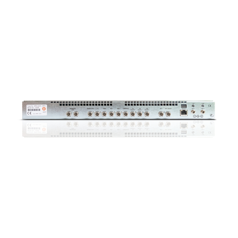
Ross SRG-2200 User manual

Ross

Ross SRG-2200 User manual

Ross RCS-8120 User manual

Ross

Ross RCS-8120 User manual

Ross GRAPHITE-4RU-1ME-9IN User manual

Ross

Ross GRAPHITE-4RU-1ME-9IN User manual

Popular Recording Equipment manuals by other brands

Axxess GMOS-LAN-10 installation instructions

Axxess

Axxess GMOS-LAN-10 installation instructions

Audient iD24 quick start guide

Audient

Audient iD24 quick start guide

Brainchild HMI 4.3 user manual

Brainchild

Brainchild HMI 4.3 user manual

beier USM-RC-2 operating manual

beier

beier USM-RC-2 operating manual

Coomber 43400 Series instruction manual

Coomber

Coomber 43400 Series instruction manual

Roland JD-08 owner's manual

Roland

Roland JD-08 owner's manual

Alesis airFX Reference manual

Alesis

Alesis airFX Reference manual

Philips VoiceTracer DVT7500 quick start guide

Philips

Philips VoiceTracer DVT7500 quick start guide

Fostex PD-4 owner's manual

Fostex

Fostex PD-4 owner's manual

Matrox Monarch HD user guide

Matrox

Matrox Monarch HD user guide

Philips CDR870 user manual

Philips

Philips CDR870 user manual

vpme.de trig31 user manual

vpme.de

vpme.de trig31 user manual

Art SGE MACHK II MULTI-EFFECTS manual

Art

Art SGE MACHK II MULTI-EFFECTS manual

EVS LSM-VIA Installation and configuration manual

EVS

EVS LSM-VIA Installation and configuration manual

Harman Kardon CDR 26 Product View

Harman Kardon

Harman Kardon CDR 26 Product View

Steinberg UR 28 M Operation manual

Steinberg

Steinberg UR 28 M Operation manual

Sony BDX-N1000 installation manual

Sony

Sony BDX-N1000 installation manual

Sony MU-R201 Service manual

Sony

Sony MU-R201 Service manual

manuals.online logo
manuals.online logoBrands
  • About & Mission
  • Contact us
  • Privacy Policy
  • Terms and Conditions

Copyright 2025 Manuals.Online. All Rights Reserved.