8
GBGB
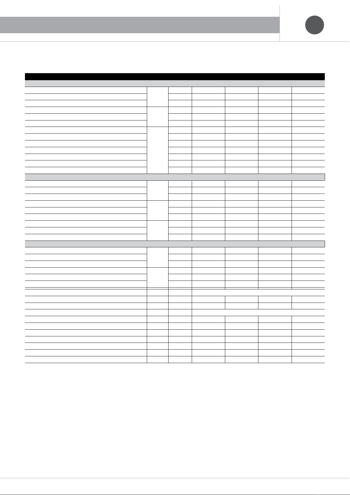
Technical Specifications
Models Ref. u.m.
EH0614DC EH1014DC EH1314DC EH1614DC
APPLICATION USING AIR TERMINAL UNITS
Nominal Thermal Power
A7 W45
kW 6,40 9,75 13,30 16,00
Nominal Absorbed Power kW 1,99 2,83 3,76 4,70
COP 3,22 3,44 3,54 3,40
Nominal Thermal Power
A-7 W45
kW 3,70 5,90 9,10 10,60
Nominal Absorbed Power kW 1,76 2,79 4,08 4,83
COP 2,10 2,12 2,23 2,20
Nominal Cooling Power
A35 W7
kW 3,95 5,53 10,70 12,60
Nominal Absorbed Power kW 1,37 1,90 3,11 4,17
EER 2,88 2,91 3,44 3,02
ESEER 4,69 4,54 5,96 5,88
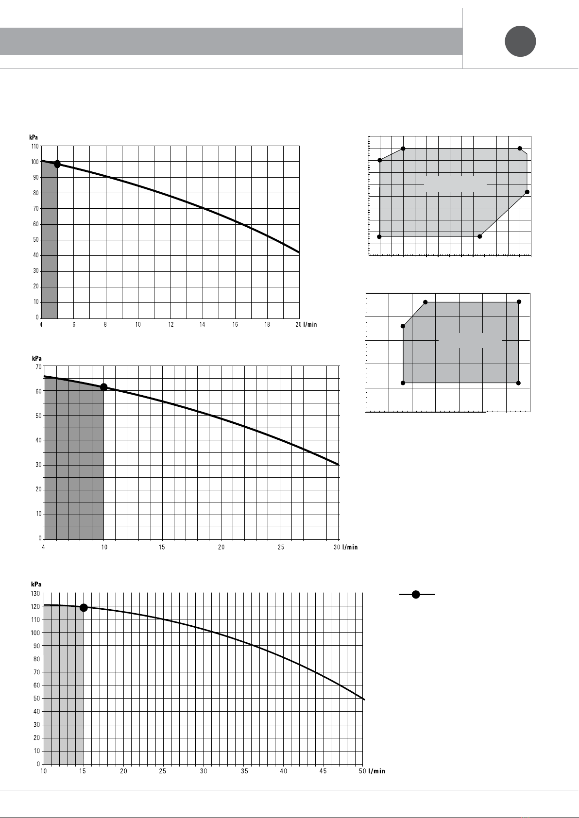
Pump - Available Pressure kPa 100 55 92 90
Noise Level dB(A) 60 62 63 63
Noise Pressure* dB(A) 38 40 41 41
APPLICATION USING HEATING PANELS
Nominal Thermal Power
A7 W35
kW 6,48 9,87 14,10 17,00
Nominal Absorbed Power kW 1,47 2,15 3,14 4,05
COP 4,40 4,58 4,49 4,20
Nominal Thermal Power
A-7 W35
kW 4,00 6,50 9,50 11,00
Nominal Absorbed Power kW 1,47 2,38 3,46 4,06
COP 2,72 2,73 2,74 2,71
Nominal Cooling Power
A35 W18
kW 5,30 7,30 14,20 16,20
Nominal Absorbed Power kW 1,32 2,02 3,05 3,98
EER 4,02 3,61 4,66 4,07
APPLICATION USING LOW-TEMPERATURE RADIATORS
Nominal Thermal Power
A7 W55
kW 5,90 9,30 12,50 14,00
Nominal Absorbed Power kW 2,31 3,26 4,38 5,01
COP 2,55 2,85 2,85 2,80
Nominal Thermal Power
A-7 W55
kW 3,10 5,40 8,70 9,20
Nominal Absorbed Power kW 1,83 3,11 4,75 4,96
COP 1,70 1,73 1,83 1,85
Electricity Supply 230V~ 50Hz
Maximum Power Absorbed kW 2,5 3,5 5,5 5,6
Maximum Current A11,2 18,3 25,3 25,3
Compressor Type Twin Rotary
R410 Refrigerant kg 1,05 1,60 2,99 2,99
Water Connections Ø3/4” 1” 1” 1/4 1” 1/4
Maximum Water Pressure bar 3,0 3,0 3,0 3,0
Width mm 850 874 1024 1024
Height mm 675 882 1420 1420
Depth mm 315 345 356 356
Weight kg 52 77 118 118
Data in relation to the following conditions:
A35 W18 Air: 35 °C - Water: 18/23 °C
A35 W7 Air: 35 °C - Water: 7/12 °C
A7 W35 Air: 7(6) °C - Water 30/35 °C
A7 W35 Air: -7(-8) °C - Water G/35 °C. G=water range the same as in condition A7 W35
A7 W35 Air: 7(6) °C - Water 40/45 °C
A7 W35 Air: -7(-8) °C - Water G/45 °C. G=water range the same as in condition A7 W35
A7 W35 Air: 7(6) °C - Water 47/55 °C
A7 W35 Air: 7(-8) °C - Water G/55 °C. G=water range the same as in condition A7 W35
(*) In an open area (Q = 2) 5 metres from the unit.
(European Seasonal Energy Efficiency Rating)
Performance in accordance with EN 14511:2011.
3. TECHNICAL SPECIFICATIONS