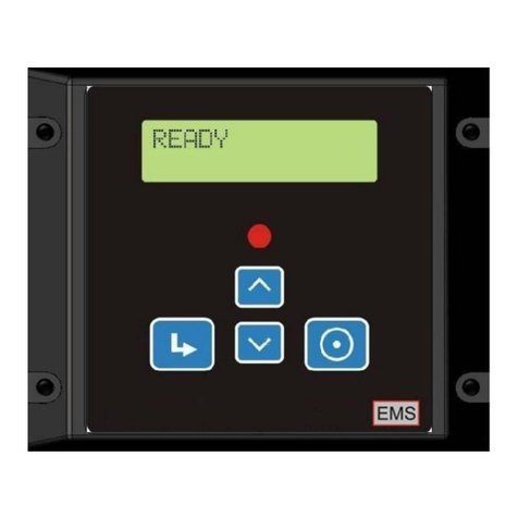
EMS EMS827 User manual

EMS827
AMF Genset Controller
User Manual
This document applies to Product
9001-xxxx
Build Version
3600-xxxx
Firmware Version
5000-xxxx
Version History:
S. No.
Version No.
Changes Made
Date Modified
Modified By
Approved By
1
2
3
www.ems.gen.nz
The information contained in this document is copyright, and
shall not be reproduced without the written authority of EMS
©2010

EMS 827
GENSET CONTROLLER
Confidential www.ems.gen.nz Page 2
Contents
1. Introduction ...............................................................................................................................4
2. Benefits .....................................................................................................................................4
3. Physical Form .............................................................................................................................5
4. Functions ...................................................................................................................................6
4.1 System...............................................................................................................................6
4.2 Engine Monitoring...............................................................................................................6
4.3 Generator Monitoring..........................................................................................................8
4.4 Mains AC Monitoring...........................................................................................................8
4.5 System LED Indications ........................................................................................................8
4.6 Transfer Control LED Indications ...........................................................................................9
4.7 System LCD Displays ............................................................................................................9
4.8 AC Inputs..........................................................................................................................10
4.9 Analog Inputs....................................................................................................................10
4.10 Digital Inputs ....................................................................................................................10
4.11 Outputs............................................................................................................................11
5. Operation ................................................................................................................................12
5.1 Buttons ............................................................................................................................12
5.2 LEDs ................................................................................................................................13
5.3 Initial Power Up ................................................................................................................14
5.3.1 Ready...........................................................................................................................14
5.3.2 Mode Selection .............................................................................................................14
5.4 Manual Operation.............................................................................................................15
5.4.1 To start the genset.........................................................................................................15
5.4.2 To stop the genset .........................................................................................................16
5.5 Autostart Engine Control....................................................................................................16
6. Display Operation .....................................................................................................................17
6.1 When the genset is running................................................................................................17
7. Alarms and Warnings ................................................................................................................21
7.1 Inputs Electrical Specification .............................................................................................26
7.2 Outputs Electrical Specification...........................................................................................28
8. Load Transfer and Contactor Operation.......................................................................................29
9. Speed Sensing ..........................................................................................................................29
9.1 MPU ................................................................................................................................29
9.2 Magneto ..........................................................................................................................29
9.3 Generator ........................................................................................................................30
9.4 Battery Charging Alternator................................................................................................30
10. Battery Charging Alternator Excitation ....................................................................................31
11. Battery Voltage Monitoring and Charging Detection .................................................................31
12. Set-up .................................................................................................................................32
12.1 Navigating in the setup menu .............................................................................................32
12.2 System Column .................................................................................................................33
12.3 Engine Column..................................................................................................................33
12.4 Timers Column..................................................................................................................38
12.5 Contactor A Column ..........................................................................................................39
12.6 Start/Stop Column.............................................................................................................39
12.7 AC Setup Column ..............................................................................................................40
12.8 AMF Setup Column............................................................................................................41
12.9 AGF Setup Column ............................................................................................................41
12.10 Testing Column.................................................................................................................42
12.11 Manual Column ................................................................................................................42

EMS 827
GENSET CONTROLLER
Confidential www.ems.gen.nz Page 3
12.12 Room Temp Column ..........................................................................................................43
12.13 Aviation Light Column (Not protected against prolonged power loss)......................................43
12.14 I/O Config Column.............................................................................................................43
12.15 Comms (Communications) Setup Column.............................................................................45
12.16 Log Viewer Column............................................................................................................45
13. Communications...................................................................................................................46
13.1 Unit General Specifications.................................................................................................46
14. Installation and Wiring ..........................................................................................................49
14.1 Connector Detail ...............................................................................................................49
15. Trouble shooting ..................................................................................................................52
16. Wiring Options .....................................................................................................................55

EMS 827
GENSET CONTROLLER
Confidential www.ems.gen.nz Page 4
EMS827
AMF Controller for
30KVA to 160KVA Gensets
1. Introduction
The unit is a controller for mid-engine Gensets with Automatic Mains Failure (AMF)
functionality sold in the private market segment.
The unit incorporates Manual, Autostart Start and AMF Autostart initiated start and stop
sequencing, monitors engine and alternator operating parameters and provides both engine
and alternator protection, in a single integrated package.
The Mains and Alternator status and operating parameters are shown by scrolling screens on a
backlit Graphics LCD. Alarms and warning are also shown on the LCD and supplemented by
status LEDs and a sounder output.
The unit provides comprehensive monitoring of the engine operating parameters and provides
automatic shutdown of the set in the event of damaging conditions. In addition to standard
engine safety protections the unit monitors battery voltage, battery status, charging
conditions, coolant level and temperature, fuel level, canopy temperature, oil pressure and
temperature, engine speed and operating hours.
On the Alternator side, the unit monitors and displays 1 or 3 phase voltages, for L-N and L-L. It
monitors the operating frequency, 3 individual phase currents, Average PF, KVA, KVAr for each
phase and Alternator total. It maintains 3 phase Power meter functions which comprise, Total
Mains KWH, Total Alternator KWH and Total Alternator KVArH,
The alternator incorporates several protection features which include Over-load, Over-current,
Load imbalance, and IDMT protection.
In the factory environment, the unit is configured by cloning through a Personal Computer (PC)
system. Field specific parameters can be adjusted by using the front panel buttons and an
inbuilt menu system.
2. Benefits
Reduces system cost:
oIntegrates engine gauges and AC metering into one unit.
oMinimises control panel wiring offering reduced material and labour costs.
Reduces warranty costs by providing comprehensive engine and generator protection
and a maintenance due timer.
Flexibility, the unit can be customised by PC cloning for individual genset model
characteristics and fitments.
Includes communications port for remote monitoring applications, dual station
operation and companion auxiliary units.
Inbuilt data logs provide operating history in the event of engine or alternator failure.

EMS 827
GENSET CONTROLLER
Confidential www.ems.gen.nz Page 6
4. Functions
4.1 System
Function
Description
Protection Shutdown
Automatic preventative engine and genset shutdown in the event
of abnormal operating conditions with optional configuration
parameters and clear LCD status messages
Manual Start
In response to the front panel pushbutton, the unit performs a fully
sequenced engine start with optional configuration parameters and
clear LCD status messages
Manual Stop
In response to the front panel pushbutton, the unit performs a fully
sequenced engine stop with optional configuration parameters and
clear LCD status messages
Auto Start / Auto Stop
In response to a digital input, the unit performs a fully sequenced
engine start or stop with optional configuration parameters and
clear LCD status messages.
AMF Start
In response to a mains failure event, the unit performs a fully
sequenced engine start with optional configuration parameters and
clear LCD status messages
AMF Stop
In response to a mains restored event, the unit performs a fully
sequenced engine stop with optional configuration parameters and
clear LCD status messages
Emergency Stop
In response to a digital input, the unit performs a fully sequenced
engine stop with optional configuration parameters and clear LCD
status messages
Manual Transfer Control
Manually initiated and automatically sequenced A and B contactor
control with optional configuration parameters and clear LCD status
messages
Automatic Transfer Control
Automatically initiated and sequenced A and B contactor control
with optional configuration parameters and clear LCD status
messages
4.2 Engine Monitoring
Function
Description
Over / Under Speed
Monitors engine speed with optional configuration parameters and
clear LCD status messages. This ensures the engine speed remains
within configured limits. Exceeding these limits will result in
automatic engine shutdown to prevent damage.

EMS 827
GENSET CONTROLLER
Confidential www.ems.gen.nz Page 7
Function
Description
Lubrication Oil Pressure
Monitors engine oil pressure with optional configuration
parameters and clear LCD status messages this ensures the oil
pressure remains within configured limits. Exceeding these limits
will result in automatic engine shutdown to prevent damage. Oil
pressure monitoring can be from an oil pressure switch, or a
resistive oil pressure sensor, or both.
Lubrication Oil
Temperature
Monitors engine oil temperature with optional configuration
parameters and clear LCD status messages this ensures the oil
temperature remains within configured limits. Exceeding these
limits will result in automatic engine shutdown to prevent damage.
Coolant Temperature
Monitors coolant temperature with optional configuration
parameters and clear LCD status messages this ensures the coolant
temperature remains within configured limits. Exceeding these
limits will result in automatic engine shutdown to prevent damage.
Coolant Level
Monitors radiator water level and provides clear LCD status
messages. Automatic engine shutdown if radiator water is low.
Battery Voltage
Monitors engine battery voltage with optional configuration
parameters and clear LCD status messages this ensures the battery
voltage remains within configured limits.
Battery Charging
Monitors engine battery charging during standby and operation
and shows the status with clear LCD status messages. Warnings are
given if charging is under or over charging.
Fuel Level
Monitors engine fuel level with clear LCD status messages. Low
fuel level will result in automatic engine shutdown to prevent
damage. A fuel loss warning and event log are included.
Canopy Temperature
Monitors engine canopy temperature with optional configuration
parameters and clear LCD status messages this ensures the engine
canopy temperature remains within configured limits. Exceeding
these limits will result in automatic engine shutdown to prevent
damage.
Running Hours
Records engine run hours with clear LCD status messages.
Service Timer
A service timer is incorporated to ensure proper service schedules
are maintained. The service message is displayed on the LCD at the
pre-programmed times. An event log is maintained for service due
and service taken.

EMS 827
GENSET CONTROLLER
Confidential www.ems.gen.nz Page 8
4.3 Generator Monitoring
Function
Description
AC Phase Voltage
Monitors 1, 2 or 3 phases of AC voltage with optional configuration
parameters and clear LCD status messages. Measurements include
L-N and L-L.
AC Phase Current
Monitors 1 or 3 Delta phases of AC current with optional
configuration parameters and clear LCD status messages.
Uses externally fitted 5A CTs.
AC Phase Frequency
Monitors 1, 2 or 3 phases of AC Frequency with optional
configuration parameters and clear LCD status messages.
AC Phase Reversal
Monitors Alternator AC for Phase reversal with optional
configuration parameters and clear LCD status messages.
AC Loading
Monitors AC load as a percentage of full load with optional
configuration parameters and clear LCD status messages.
AC Power Metering
Monitors AC power output (KW, KVA, KVAr, KWH, KVArH and Avg
PF) with optional configuration parameters and clear LCD status
messages.
4.4 Mains AC Monitoring
Function
Description
AC Phase Voltage
Monitors 1, 2 or 3 phases of AC voltage with optional configuration
parameters and clear LCD status messages. Measurements include
L-N and L-L.
AC Phase Frequency
Monitors 1, 2 or 3 phases of AC frequency with optional
configuration parameters and clear LCD status messages.
AC Phase Reversal
Monitors Mains AC for Phase reversal with optional configuration
parameters and clear LCD status messages.
Mains Failure
Monitors AC failure with optional configuration parameters and
clear LCD status messages. Includes Under and Over Voltage, Under
and Over Frequency,
4.5 System LED Indications
Function
Description
Alarm
Red LED indication of system alarm.
Manual Mode
Green LED indication that the unit is in Manual Start Mode.

EMS 827
GENSET CONTROLLER
Confidential www.ems.gen.nz Page 9
Function
Description
Auto Mode
Green LED indication that the unit is in Automatic Start Mode
Test Mode
Green LED indication that the unit is in Test Mode
4.6 Transfer Control LED Indications
Function
Description
Alternator Phase 1
Available
Red LED indication that the Alternator phase 1 voltage is available.
Alternator Phase 2
Available
Yellow LED indication that the Alternator phase 2 voltage is
available.
Alternator Phase 3
Available
Blue LED indication that the Alternator phase 3 voltage is available.
Alternator Available
Green LED indication that the Alternator is available for the load.
Alternator on Load
Green LED indication that the Alternator is on load.
Mains AC Phase 1
Available
Red LED indication that the mains phase 1 voltage is available.
Mains AC Phase 2
Available
Yellow LED indication that the mains phase 2 voltage is available.
Mains AC Phase 3
Available
Blue LED indication that the mains phase 3 voltage is available.
Mains AC Available
Green LED indication that the mains is available for load.
Mains AC on Load
Green LED indication that the mains is on load.
4.7 System LCD Displays
Function
Description
Setup menu
System configuration menus
Start Up
Clear step-by-step start up sequencing messages
Shutdown
Clear step-by-step shutdown sequencing messages
Transfer
Clear step-by-step load transfer messages

EMS 827
GENSET CONTROLLER
Confidential www.ems.gen.nz Page 10
4.8 AC Inputs
Function
Description
3 Phase Mains AC Voltage
Mains AC voltages.
3 Phase Alternator AC
Voltage
Alternator AC voltages.
3 Phase Alternator Current
Alternator AC currents via external 5A CTs.
4.9 Analog Inputs
Function
Description
Speed
Engine speed from MPU or battery charging alternator.
Lubrication Oil Pressure
Engine oil pressure. Exciting current approx 13mA
Lubrication Oil
Temperature
Engine oil temperature. Exciting Current approx 5mA
Coolant Temperature
Engine coolant temperature (Air or Water). Exciting current approx
5mA
Fuel Level
Engine fuel level. Exciting current approx 13mA
Canopy Temperature
Engine canopy temperature. Exciting Current approx 5mA
Coolant Level
Engine Radiator level. Exciting frequency 500Hz
Battery Voltage (Internal)
Battery Voltage is measured internally from DC supply point.
4.10 Digital Inputs
Function
Description
Auto Start / Stop Input
Auto start.
Close to common. Current limited 10mA at 10V
Emergency Stop Input
Emergency engine stop.
Selectable Open or Close to common. Current limited 10mA at 10V
Oil Switch Input
Oil Pressure Switch sensor.
Close to common. Current limited 10mA at 10V
Digital Input 1
Configurable. Default = Bypass. No logic control but full
instrumentation available.
Digital Input 2
Configurable. Default = Canopy door open.

EMS 827
GENSET CONTROLLER
Confidential www.ems.gen.nz Page 11
Function
Description
Close to common. Current limited 10mA at 10V
Digital Input 3
Configurable. Default = Fire. Shutdown genset and open both
contactors.
Close to common. Current limited 10mA at 10V
Digital Input 4
Configurable. Status, Warning, Alarm, PC programmed message.
Close to common. Current limited 10mA at 10V
4.11 Outputs
Function
Description
Excitation Output
Alternator excitation control and feedback. 200mA Pulsed
Preheat Output
Open drain engine preheat control. Open Drain 300mA /36V DC
Fuel Output
Open drain fuel solenoid control. Open Drain 300mA /36V DC
Crank Output
Open drain engine crank control. Open Drain 300mA /36V DC
Idle Output
Open drain engine idle control. Open Drain 300mA /36V DC
Hooter Output
Open drain audible sounder control. Open Drain 300mA /36V DC
Common Alarm Output
Open drain audible sounder control. Open Drain 300mA /36V DC
Contactor A Output
Open drain transfer contactor A control. Open Drain 300mA /36V
DC
Contactor B Output
Open drain transfer contactor B control. Open Drain 300mA /36V
DC

EMS 827
GENSET CONTROLLER
Confidential www.ems.gen.nz Page 12
5. Operation
Front Layout
5.1 Buttons
Button
Function Description
MODE
Mode button
Used to change mode between manual, auto and test
START
Start button / Menu Previous
1. Used to initiate generator start sequence
2. Used as system menu previous button
STOP
Stop button / Menu Next
1. Used to initiate generator stop sequence
2. Used as system menu next button
Accept button / Setup Menu Entry
1. Used to accept system events and silence the sounder
2. Used to enter the Setup mode

EMS 827
GENSET CONTROLLER
Confidential www.ems.gen.nz Page 13
Button
Function Description
Mains Transfer Button
Used to start transfer sequence of load from genset to mains
Genset Transfer Button
Used to start transfer sequence of load from mains to genset
Screen Scroll up / Setup menu up Button
1. Screen Scroll up Button
2. Used as the system menu up and value increment button
Screen Scroll down / Setup menu down Button
1. Screen Scroll up
2. Used as the system menu down and value decrement
button
5.2 LEDs
Button
Function Description
Alarm
Indicates system alarm
Genset Available
Indicates that the genset is available to go on load
Genset On Load
Indicates that the genset is currently on load
Alternator Phase Status
Indicates the phases which are available from the genset
1. Red –Phase 1
2. Yellow –Phase 2
3. Blue –Phase 3
Mains Available
Indicates that the mains supply is available to go on load
Mains On Load
Indicates that the mains supply is currently on load

EMS 827
GENSET CONTROLLER
Confidential www.ems.gen.nz Page 14
Button
Function Description
Mains Supply Phase Status
Indicates the phases which are available from the mains
1. Red –Phase 1
2. Yellow –Phase 2
3. Blue –Phase 3
Manual Mode
Indicates that the system is in manual mode
Auto Mode
Indicates that the system is in automatic mode
Test Mode
Indicates that the system is in test mode
5.3 Initial Power Up
On power up, the unit displays the Logo.
The unit then displays the Serial number, Application Code and Firmware version.
After the initialisation process is complete, the unit waits for a Start request (Start Button,
AMF failure or Auto Start Input), during which time it will display ‘READY’.
5.3.1 Ready
When the unit is in READY all measuring systems and display systems are turned on. The
unit remains on for 1 minute and if the genset is not started in that time the unit goes into
sleep mode to conserve battery power. In this mode the unit wakes periodically to check
for any unusual conditions and if it finds none it goes back to sleep, otherwise it alarms
accordingly. Where ‘awake’ mode has been selected the system parameters are
continuously scrolled.
Any activity on the buttons immediately wakes the unit and the appropriate action is
taken.
Pressing the STOP button while the unit is asleep immediately wakes the unit and scrolls all
engine and generator parameter screens. This allows reading of battery voltage, fuel level,
and run hours KWH etc.
5.3.2 Mode Selection
The unit may be operated in Auto, Manual, Test or Stop modes. The mode is selected by
pressing the mode button. The mode is indicated on the LCD and the LED associated with
the mode buttons.
The engine can be stopped with the Stop button in MANUAL, AUTO or TEST modes.

EMS 827
GENSET CONTROLLER
Confidential www.ems.gen.nz Page 15
In MANUAL mode the unit responds only to the manual push button and may control A
and B contactors if these options have been enabled.
In the AUTO mode, the unit responds to the autostart input or Remote Starts and controls
A and B contactors.
In TEST mode the engine responds only to the manual start button and runs for a preset
test time if configured. Contactors are not controlled
5.4 Manual Operation
5.4.1 To start the genset
When the display is showing READY, press the start
START
button momentarily to start the
genset. The READY state implies the engine and generator parameters are as expected for
a stationary genset. If the conditions are not as expected, an appropriate warning or alarm
is displayed on the LCD. The warning or alarm condition must be cleared before the genset
can be started.
The unit will perform the starting sequence as follows:
FUEL-ON.
oIf ETR (Energise To Run) fuel control is configured, the unit will control the fuel
output and display FUEL ON and the proceeds to the CRANK state.
oFor ETS (Energise To Stop) the sequence does not activate the output but
proceeds after a short delay to the CRANK state.
CRANK.
oThe crank output is activated and the display shows ‘Cranking’ with a count
down time.
oThe crank output is deactivated when the unit has detected a speed signal
above the crank disconnect speed specified in the settings, or has detected oil
pressure above the minimum oil pressure specified in the settings or Excitation
is present
oIf the genset does not start, the LCD will show ‘Stopping’, control the Fuel and
Crank outputs accordingly, and return to READY. No retries are done.
oIf the unit looses power due to battery voltage drop during cranking, and the
engine fires, then on regaining adequate battery voltage, the unit will continue
to allow the engine to run. This typically ONLY happens with ETS fuel systems.
RUN UP.
oWhen the engine starts, the display shows ‘Run Up’ with a count down in
seconds. This allows the engine measurement system to stabilise. Over speed
and loss of speed signal are the only parameters checked during Run Up.
WARM UP

EMS 827
GENSET CONTROLLER
Confidential www.ems.gen.nz Page 16
oAllows the engine to stabilise at full speed before going on load. Oil pressure
and Over-speed are monitored. The display shows ‘Warm Up’ with a
countdown time.
RUNNING
oThe display shows ‘Running’. Operating parameters are scrolled onto the
display.
5.4.2 To stop the genset
Push the
STOP
button briefly.
The unit will perform a stopping sequence as follows:
STOPPING
oThe display will show ‘Stopping’ with a countdown time.
oIf ETR fuel control has been selected the Fuel output will be de-energised.
oIf ETS fuel control has been selected then the Fuel output will be energised for
the Max Fuel Time or until the engine stops. The stopping process will retry if
the engine fails to stop the first time. During the ‘ETS Rest period’ the Fuel
output is deactivated.
oThe fuel output is controlled until the engine stops rotating and oil pressure
decays. If the Oil Pressure has not decayed by the end of the ‘Max Fuel Time’,
the fuel output is deactivated and the controller waits until the oil pressure has
decayed, or for the remainder of the ‘Stop Time’. The speed must remain at
zero and the oil pressure must be below the alarm set point for the ‘Stop Rest
Time’ before the engine is considered stopped.
oIf the genset does not stop then the alarm output is activated and ‘STOP FAIL’ is
displayed on the LCD.
READY
oThe engine has stopped and is ready to start again as required.
5.5 Autostart Engine Control
If the Autostart input is activated, the unit will initiate an Autostart sequence. The
sequence is similar to the manual start and stop sequences above with the following
additions.
An adjustable Start Delay follows the Autostart input activation. This is usually
configured to avoid nuisance starting. The Display shows “Starting” with a
countdown value. For long start delays, the start time units may be set to minutes.
If the autostart restores for more than the Start Restore time, then the start
sequence is aborted.

EMS 827
GENSET CONTROLLER
Confidential www.ems.gen.nz Page 17
The unit cranks the engine for the crank time or until the engine fires. If the engine
does not fire after the crank time, then the unit will repeat the crank procedure
after waiting for the crank rest time. This cycle is repeated for the “Crank Retries”
and if the engine has not started after the last cycle, a “Fail to Start” alarm is
generated.
The Start sequence now follows the manual starting sequence until the engine is
running.
During an Autostart run the LCD displays Auto in the top left of the display.
The stopping sequence is initiated by deactivation of the autostart input. The engine does
not stop immediately as there are three additional states in the Auto stopping sequence.
“Run On” follows “Running” and is a provided as an adjustable delay to reduce
nuisance stopping. The Contactor A & B Outputs remain activated and the Display
shows “Run On” with a countdown value. If the autostart input is re-activated
during “Run On” the unit returns to normal “Running” until the Autostart input is
deactivated.
“Cool Down” follows “Run On” and allows the engine and/or generator to cool
down before stopping. The cool time is adjustable. At the start of “Cool Down” the
Contactor A & B Outputs are deactivated, transferring the load to the mains. The
display shows “Cool Down” with a countdown. If the autostart input is re-activated
during “Run On” the unit returns to normal “Running” and Contactor A and B are
activated.
“Idle down” follows “Cool Down”. The engine runs at idle speed for the idle down
time. If the autostart input re-activated during Idle Down, then the unit returns to
the Warm Up state and continues its starting sequence from there in the normal
manner.
Pressing the Stop button in auto mode stops the engine immediately, deactivates the
Contactor A & B Outputs, and changes the mode of the unit to Manual.
6. Display Operation
6.1 When the genset is running
When the genset is starting and stopping, the display shows the state of the sequence
together with the time remaining before the next state will commence.
Once the genset is fully running or if the genset is stopped and in ‘READY’, the running
parameters are displayed. This includes generator and engine parameters simultaneously
on separate displays. The unit sequentially scrolls through screens as shown below:
Table of contents
Other EMS Controllers manuals
Popular Controllers manuals by other brands

Barco
Barco EC-30 quick start guide

Metso
Metso Quadra-Powr X Installation maintenance and operating instructions

VAT
VAT 653 Series Installation, operating, & maintenance instructions

Smartgen
Smartgen MGC120 user manual

Johnson Controls
Johnson Controls VAP Series Installation instruction

Data Technology
Data Technology 5160X installation guide