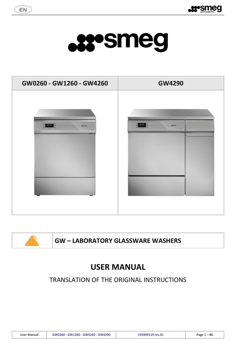
Smeg GW0160 User manual

1
SERIE GW0160 - GW2145 - GW1160 - GW4060 - GW4190
SERIE PW4060
SERIE WD2145 - WD1160 - WD4060 - WD4190
- TECHNICAL MANUAL -
19 490 0015 06 – EN 13/06/2016 Heading, new m dels: GW0160, PW4060
Manual Ed. Date Rev. Note
1 INTROD CTION
This d cument is a c mpendium intended f r the use f auth rised engineers.
It must be used:
1. By the engineers who have been specifically trained by the manufacturer t perf rm maintenance w rk n the pr duct
2. In association with the device’s user manual
3. In association with the latest-version electrical and functional diagrams.
Alth ugh this is n t always necessary, it sh uld be remembered that the “Tracelog” software made available by the manufacturer
all ws c mmunicati n with the instrument/glassware washers c vered and is a useful troubleshooting aid f r technical staff.
F r details f spare parts and the latest-versi n d cumentati n, please visit www.smegtech.c m.
The diagrams sh wn can als be d wnl aded in pdf f rmat fr m the www.smegtech.c m website.
N.B.:
The diagrams sh wn bel w refer t the GW4060 and WD4060 m dels.
F r c mplete technical d cumentati n f r all the m dels in the range, visit www.smegtech.c m
The training f technical staff, pr vided by the main Cust mer Care service, is essential f r the c rrect maintenance r repair f
devices.
2 START- P
The user is responsible for preparing the utility systems required t all w the device t be c nnected and supplied c rrectly and
for positioning the device.
Refer t the user manual and the “INSTALLATION REQUIREMENTS” d cument.
The authorised engineer puts the device into service, checking:
1. that it has been installed correctly:
a. plumbing h kup;
b. electrical h kup;
c. that it is p siti ned in acc rdance with the relative requirements;

2
2. That the device is operating and has been set up correctly:
a. date/time setting;
b. mains water hardness setting;
c. demineralised water yes/no setting;
d. setting f the presence of optionals as appr priate f r the m del c ncerned (e.g. P3, Acquast p, “FLSW” fl w
switches, etc).
In additi n t the ab ve checks, the engineer must:
1. Run program “16 SERVICE”, preferably twice in successi n, t prime the detergent intake lines correctly.
2. Run a complete cycle (with drying phase if featured in the m del) and test the device t ensure that it is perating
c rrectly (e.g. test program accessible fr m the device's SETUP menu).
The operations summarised above must be performed and recorded in accordance with the checklist provided by the
manufacturer, using the “IN-SERVICE TEST RECORD” form (“REG STRAT ON OF CORRECT OPERAT ON AT THE USER'S
S TE”) .
The authorised engineer is responsible for training the staff assigned to use the device at the time of installation.
The device may nly be used by specifically trained staff.
The training f the staff resp nsible must include specific inf rmati n n the p ssible risks inv lved in the use f the device, and
training in the safest p ssible way f carrying ut the perating pr cedures.
The installati n engineer is als resp nsible f r notifying the responsible authority of the SER and S PER SER passwords f r
access t the setup parameters.
2.1 TEST PROGRAM
F r firmware versi n pri r t 4.6: the test pr gram c nsists f just 2 phases plus a sh rt drying phase ( nly if the drying system is
installed n the m del.
- PHASE 1: c ld wash
- PHASE 2: thermal disinfecti n at 93 ° C, 10 minutes.
Water intake per phase: 9 litres (sh wn in the illustrati n as “C ld Water: 90”, referring t the value in decilitres. 90 decilitres = 9
litres).
Test program detail, for fw version prior to 4.6
===========================================================================
PHASE 1
Cold Water: 90
P1 DETERGENT (ml/l): 10
P3 DETERGENT (ml/l): 10
TARGET Temperature 1 (°C): 0 Extension (min): 1
=========================
PHASE 2
Demi Water: 90
P2 DETERGENT (ml/l): 10
TARGET Temperature 1 (°C): 93 Extension (min): 10
=========================
DRY NG
Drying temperature (°C): 110
Drying duration (min): 10
From fw version 4.6: the test progr m consists of 2 ph ses plus short drying ph se.
The PHASE 1 h s been modified: T_t rget 93°C, holding time 10 min. The principles for ctiv tion
of the dispenser pump nd drying system (when inst lled) re unch nged.
- PHASE 1: thermal disinfecti n at 93 ° C, 10 minutes, chemicals d sage
- PHASE 2: thermal disinfecti n at 93 ° C, 10 minutes.
The purp se f using tw successive PHASES at 93 ° C is t all w an eventual adjustment with external calibrated pr be, during the
first phase, and t check the pr per maintenance f the calibrati n in the sec nd phase.

3
Test program detail, for fw version following the 4.6
===========================================================================
PHASE 1
Cold Water: 90
P1 DETERGENT (ml/l): 10
P3 DETERGENT (ml/l): 10
TARGET Temperature 1 (°C): 93 Extension (min): 10
=========================
PHASE 2
Demi Water: 90
P2 DETERGENT (ml/l): 10
TARGET Temperature 1 (°C): 93 Extension (min): 10
=========================
DRY NG
Drying temperature (°C): 110
Drying duration (min): 10
Test pr gram activati n pr cedure:
1. Access the SET P screen as described in the user manual, by entering the “technician” level passw rd (c ntact the
manufacturer t btain the passw rd if necessary);
2. Scr ll thr ugh the parameters t pti n “ – t”;
3. Use the selecti n butt ns t change the screen setting fr m “--” t “on” and c nfirm;
4. Quit the SETUP m de (h ld d wn the “OPEN DOOR” butt n);
Fig. 1 - contents of Display, test program activation.
On c mpleti n f the pr cedure, the display sh ws “Pr t”.
The nly pr gram available at this p int is the test pr gram; if y u d n t wish t c ntinue, switch the device ff and back n.
WARNING
The test program “Pr t” is intended solely for testing that the inputs and outputs are
activated correctly. It does not constitute w shing progr m nd must never be
considered s such.

4
3 F NCTIONAL DIAGRAM
N.B.:
The diagrams sh wn bel w refer t the GW4060 and WD4060 m dels. F r c mplete up-t -date digital d cumentati n f r
all the m dels in the range, visit www.smegtech.c m

5
4 WIRING DIAGRAM
In revision 04 of the present Technical Manual, the wiring diagram is cancelled from this section
to leave only the official updated reference, on www.smegtech.com, for authorized tecnicians.
F r c mplete up-t -date digital d cumentati n always c nsult www.smegtech.c m
5 KEY TO ABBREVIATIONS
AQS: Acquast p ( pti nal) - micr switch
BPE: Electric l ck
DD: P wder detergent dispenser (GW series nly)
EVCC: C ndenser filling s len id valve
EVD: Demineralised water s len id valve
EVF: C ld water s len id valve
EVR: S ftener resin regenerati n s len id valve
FMD (FLMT_D): demineralised water fl wmeter
FMF (FLMT_F): C ld water fl wmeter
FLSW1, FLSW2, FLSW3: detergent dispensing fl w switches
KR: Chamber heating element c ntr l relay
MA: Dryer m t r
MCM: D r cl sure micr switch
ML: Washing pump
MS: Chamber drain pump
P1, P2, …, P10: PCB c nnect rs
P1, P2, P3: Peristaltic detergent feeder pumps (P3 is always pti nal)
PAP: High pressure switch (f r m nit ring perati n f washing pump ML)
PLA: chamber safety/level anal gue pressure sens r
PLC: C ndenser pressure switch (used as level sens r in the steam c ndenser)
PSC: Steam c ndenser drain pump
R1, R2, R3: Chamber heating elements
RA: Drying System heating element
SF: RFI filter
SL1, SL2, SL3: Detergent jerry can level sens rs
SS: Salt sens r (salt level in integral s ftener tank)
TA: PT1000 pr be f r drying system air temperature
TCL: PT1000 pr be f r m nit ring chamber water temperature
THS1: Safety therm stat f r heating element R1
THS2, THS3: Safety therm stats f r R2, R3
TL1: PT1000 pr be f r chamber water w rking temperature
TS1, TS2: Drying heating element safety therm stats
X1: Main terminal b ard (p wer supply)
XCT: “V ltage change” terminal b ard
Other manuals for GW0160
1
This manual suits for next models
9
Table of contents
Other Smeg Laboratory Equipment manuals
Popular Laboratory Equipment manuals by other brands

Belden
Belden HIRSCHMANN RPI-P1-4PoE installation manual

Koehler
Koehler K1223 Series Operation and instruction manual

Globe Scientific
Globe Scientific GCM-12 quick start guide

Getinge
Getinge 86 SERIES Technical manual

CORNING
CORNING Everon 6000 user manual

Biocomp
Biocomp GRADIENT MASTER 108 operating manual