GHSP grenlite UV-C System User manual

9 JUNE 2021 P a g e | 1 INSTALLATION
grēnlite™ UV-C System
Installation Manual
GHSP, In
1250 South Bee htree
Grand Haven, MI
49417
USA

9 JUNE 2021 P a g e | 2 INSTALLATION
The grēnlite™ is a UV-C system that uses high dose and low dose UV-C light to disinfe t the inside of
vehi les. The UV-C system:
Redu es 99.9% of viruses and ba teria that ause disease
Kills 99.9% of human oronavirus and COVID 19
Uses up to 3 units to omplete the disinfe tion pro ess
Follow the pro edures and pre autions in this manual to install the UV-C system in a vehi le.
1ABOUT THIS MANUAL
This manual is to install the grēnlite™ UV-C system. Follow the pro edures below to do the following:
Install the produ t
Test the produ t after installation
Comply to safety on erns
1.1 W
HO
S
HOULD
U
SE THIS
M
ANUAL
This manual is intended for upfitters and installers. Upfitters prepare a vehi le prior to the install of the
UV-C system. Installers install the UV-C system on the vehi le.
Upfitters can also install the UV-C system after the vehicle is prepared.
1.2 S
YMBOLS USED IN THIS MANUAL
The following symbols are used in this manual to indi ate risks or important information.
This symbol identifies an ele tri al
sho k or burn hazard.
This is the safety alert symbol. It is used in
this manual to alert you to potential
personal injury hazards.
This symbol identifies additional or
helpful information
2HOW THIS MANUAL IS ORGANIZED
Chapter
Topics
1
Overview of the manual
2
Organization of the manual
3
Definitions of terms used in this manual
4
R
equirements for the
UV
-
C system
to work
5
Information to prepare for the installation
6
Important safety information
7
The pro edure to install the
UV
-
C system
on the
vehi
le
8
The pro edure to verify
the installation
9
Troubleshooting
when the system
does not meet expe tations

9 JUNE 2021 P a g e | 3 INSTALLATION
10
Wiring Diagram
11
The warranty statement
12
How to get help
from the manufa turer
3GLOSSARY
Dosing unit- A UV-C lamp assembly that mounts to a vehi le and uses UV-C bulbs to disinfe t the
surfa es inside the vehi le.
grēnlite™- A brand of UV-C produ ts from GHSP that redu e ba teria, spores, viruses, yeasts and molds
inside vehi les.
Upfitter- A spe ialized installer who prepares the vehi le prior to the installation of the UV-C system. An
Upfitter an also install the UV-C system after the vehi le is prepared.
4REQUIREMENTS
The following se tions identify the requirements for the vehi le and the installer. These requirements
must be followed for proper fun tion of the UV-C system.
4.1 E
LECTRICAL
R
EQUIREMENTS
The ele tri al requirements for the ambulan e are listed below. For additional information about
the ele tri al requirements, see the Wiring Diagram in se tion 10.
Battery bank with 9-16 volts dire t urrent (VDC)
Chassis ground from the oa h NEG lug to the hassis
A ess to all door input signals
Cable between the POS and the oa h battery bank must be suffi iently rated. The able
must safely arry 5 amps for ea h dosing unit in the vehi le.
Master power disable relay located between the coach POS lug and the coach battery
bank. The relay should be normally open and will be piloted and closed when the Master
Enable Switch on the control panel is turned to the On position
5PREPARE FOR THE INSTALLATION
5.1
COMPONENTS
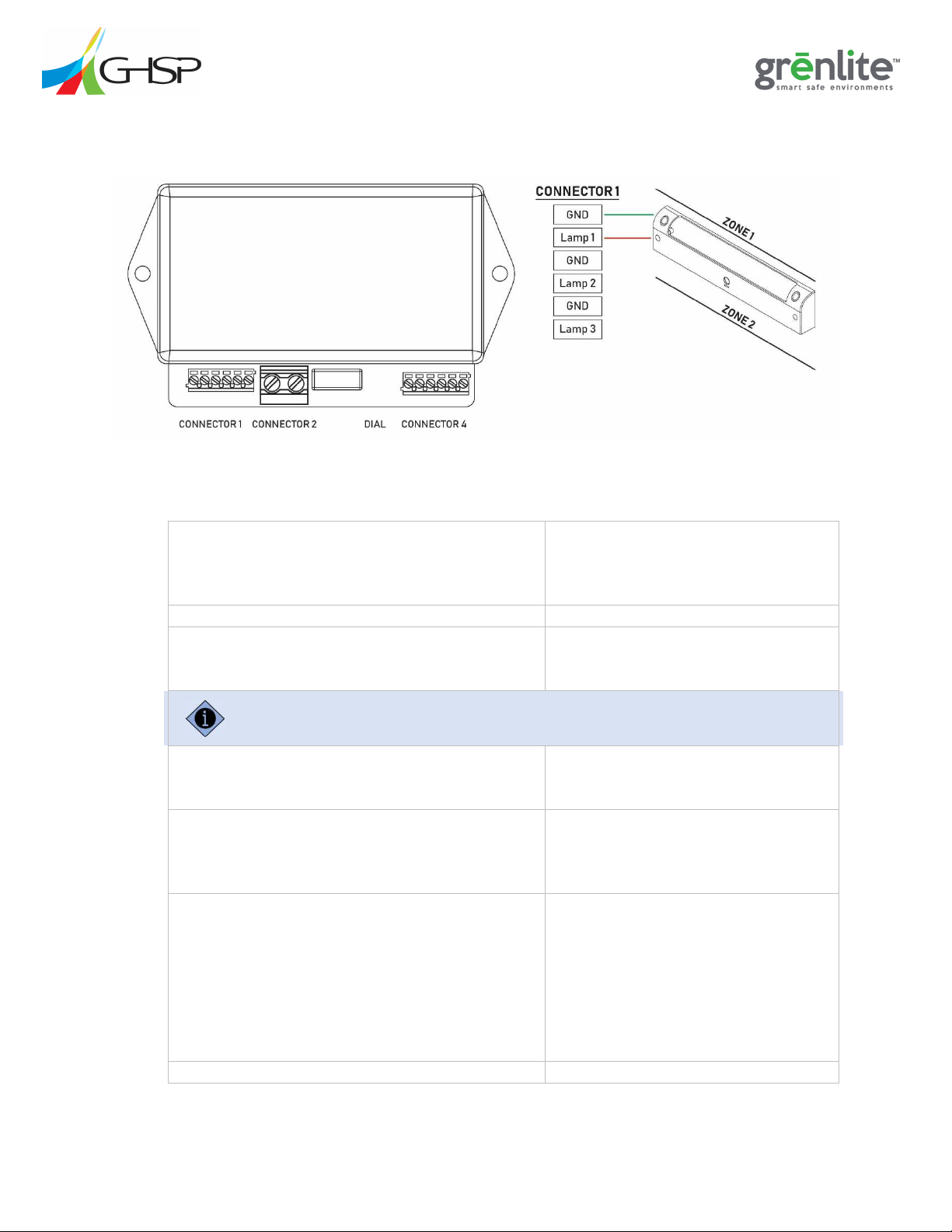
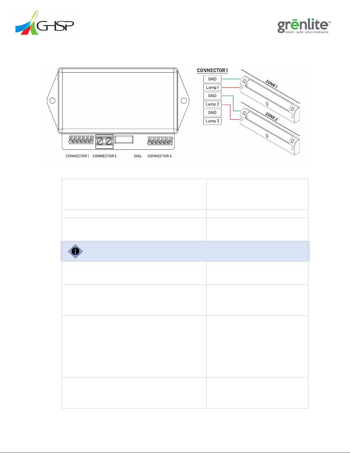
The system uses the following omponents with integrated ele tri al onne tions.
Dosing units
o400mm grēnlite lamp
o200mm grēnlite lamp
1 mating ele tri al onne tor, per dosing unit

9 JUNE 2021 P a g e | 4 INSTALLATION
Refer to the GHSP mounting guidelines at www.grenlite.com support. Make sure the mounts comply to
the SAE J3043 standard. The mount must withstand a vertical force 25 times the weight of the assembly.
System onfiguration drawing
Wire diagram
Refer to the system configuration drawing for exact quantities for the custom systems.
5.2 T
OOLS
N
EEDED FOR THE
I
NSTALLATION
The following tools are needed to install the UV-C system onto a vehi le.
12 VDC power supply
Wire strippers
Wire rimpers
Torque wren h
Safety glasses
Digital Multimeter (DMM)
6IMPORTANT SAFETY INFORMATION
Read and follow all instru tions and warnings in this manual before use. Read and follow all instru tions
and warnings in the vehi le manual before use.
W RNING!
High Intensity Ultraviolet Light Hazard
UV-C light exposure an damage eyes and skin. To avoid serious injury, prote t against UV-C exposure
when the light is ON:
Wear prote tive safety glasses ertified for UV-C exposure.
Cover all skin when UV-C exposure is possible. Use the re ommended safety equipment below:
oFa e shield
oUV resistant gloves
oArm length lothing
When a unit is tested before installation, to prote t the tester, use a transparent plexiglass shield or
en losure between the unit and the tester.
Equipment Misuse Hazard
To avoid risk of serious injury or death:

9 JUNE 2021 P a g e | 5 INSTALLATION
Do not alter or modify the unit.
Never operate the UV-C system when a bulb or the unit is broken. Inspe t the unit daily.
Use the UV-C system only for the intended purpose. Follow this manual.
Turn OFF and dis onne t the unit prior to maintenan e.
The permissible exposure limit to UV-C is a maximum of 6.0mJ cm2 for an 8 hour period for humans. For more
information on UV exposures thresholds limits, refer to recommendations from the American Conference of
Governmental Industrial Hygienists (ACHIH) at http: www.acgih.org.
6.1 B
ULB
D
ISPOSAL AND
U
NIT
D
ISPOSAL
Dispose of any dosing unit with a broken bulb. Please dispose of bulb and unit in an environmentally
safe way a ording to lo al waste disposal regulations. Always remember to re y le.
To dispose of a broken bulb, follow the guidelines from the Environmental Protection Agency (EPA) at this
location:
https://www.epa.gov/cfl/recycling-and-disposal-cfls-and-other-bulbs-contain-mercury

9 JUNE 2021 P a g e | 6 INSTALLATION
7INSTALL
Only upfitters and installers trained by GHSP may install the UV-C system. Upfitters and installers
must be certified to the CAAS-GVS-V2.0 standard from the Commission on Accreditation of
Ambulance Services (CAAS).
1. Put the qui k referen e ard in the glovebox of the vehi le.
2. Identify the lo ation for the dosing unit on the system onfiguration drawing.
3. Add prote tive barriers between ompartments If the system will fun tion while the vehi le is in
use.
4. Identify the lo ation for the dosing unit in the vehi le.
5. W RNING! Turn the power off. Refer to the safety precautions recommended by the vehicle
manufacturer.
6. Route the wire in the vehi le a ording to the ele tri al installation spe ifi ation.
7. Conne t the mating ele tri al onne tor to the wires.
Use Molex crimper tools according to the Molex specifications to connect the connector to the wires.
8. Remove the dosing unit from the box and the pa kaging.
9. Verify the mounting surfa e in the vehi le will se urely a ommodate the dosing unit.
Mount the dosing unit on a structural surface. An example of a structural surface is an aluminum beam.
Custom brackets may be required. The mounting surface must withstand a 20 lb. pull force.
10. Verify the dosing unit onfiguration is orre t for the vehi le.
11. Snap the wire harness on the dosing unit into the mating ele tri al onne tor.
12. Use a digital multimeter to do a ontinuity he k to make sure the metal lamp housing has
ontinuity to the Neg LUG of the power distribution system.
13. Tu k the ex ess wire in the hole in the eiling of the vehi le.
14. Atta h the dosing unit to the vehi le with two mounting s rews.

9 JUNE 2021 P a g e | 7 INSTALLATION
NOTICE: To ensure proper fun tion, make sure the orientation and the lo ation of the dosing
unit mat hes the system onfiguration drawing.
Use the appropriate mounting screws for the mounting surface.
15. Torque the s rews.
The screws must withstand a 30 pound pull force.
16. Install the s rew ap on the mounting s rews.
17. Repeat steps 1-16 for ea h dosing unit.
Figure 1: Dosing Unit

9 JUNE 2021 P a g e | 8 INSTALLATION
7.1 C
ONFIGURE
ESS2 -1
/
4 -1
The ESS200-1 / 400-1 has one dosing unit.
Figure 2: ESS200-1 400-1
1.
Simultaneously hold down
the E
-
stop and turn
on the battery power.
The unit enters the onfiguration
mode.
One long beep and one short beep
sound.
2.
Rotate the dial to position #1.
3.
Push the
E
-
stop button.
D
osing unit
#1
a tivates.
One long beep and two short beeps
sound.
To de-activate dosing unit #1, rotate the dial to position #0, and follow step #3.
4.
Rotate the dial to sele t the lamp type:
#0 for 200mm
#1 for 400mm
5.
Push the
E
-
stop button.
The parameters are set for
dosing unit
#1.
One long beep and three short beeps
sound.
6.
Rotate the dial to set the dose
time
:
#0 for 3 minutes
#1 for 5 minutes
#2 for 10 minutes
#3 for 15 minutes
#4 for 20 minutes
#5 for 25 minutes
#6 for 30 minutes
7.
Push the E
-
stop button.
The dose time is set for dosing unit
#1
.

9 JUNE 2021 P a g e | 9 INSTALLATION
Two
long
beeps
and
one
short
beep
sound.
Complete the configuration process for each lamp location even if a dosing unit isn’t installed in that
location. Use the #0 to deactivate the dosing units that are not installed.
8.
Rotate the dial to position #0.
9.
Push the E
-
stop button.
Dosing unit #2
dea tivates.
Two long beeps and two short beeps
sound.
10.
Leave the dial at position #0.
11.
Push the E
-
stop button.
The parameters are set for dosing unit
#2.
Two long beeps and three short beeps
sound.
12.
Leave the dial at position #0.
13.
Push the E
-
stop button.
The dose time is set for
dosing unit #2
.
Three long beeps and one short beep
sound.
14.
Leave the dial at position #0.
15.
Push the E
-
stop button.
D
osing unit
#3
dea tivates.
Three long beeps and two short beeps
sound.
16.
Leave the dial at position #0.
17.
Push
the E
-
stop button.
The parameters are set for dosing unit
#3.
Three long beeps and three short
beeps sound.
18.
Leave the dial at position #0.
19.
Push the E
-
stop button.
The dose time is set for dosing unit #3.
The programming is omplete.
A musi al beep sounds.

9 JUNE 2021 P a g e | 10 INSTALLATION
7.2 C
ONFIGURE
ESS2 -2
/
4 -2
O
PTION
1
The ESS200-2 / 400-2 Option 1 has two dosing units that operate independently.
Figure 3: ESS200-2 400-2 Option 1
1.
Simultaneously hold down the E
-
stop and turn
on the battery power.
The
unit
enters the onfiguration
mode.
One long beep and one short beep
sound.
2.
Rotate the dial to position #1.
3.
Push the E
-
stop button.
D
osing unit
#1
a tivates.
One long beep and two short beeps
sound.
To de-activate a dosing unit, rotate the dial to position #0, and follow step #3.
4.
Rotate the dial to sele t the
dosing unit
type:
#0 for 200mm
#1 for 400mm
5.
Push the E
-
stop button.
The parameters are set for
dosing
unit #1.
One long beep and three short beeps
sound.
6.
Rotate the dial to set the
dose time
:
#0 for 3 minutes
#1 for 5 minutes
#2 for 10 minutes
#3 for 15 minutes
#4 for 20 minutes
#5 for 25 minutes
#6 for 30 minutes
7.
Push the E
-
stop button.
The dose time is set for
dosing unit
#1.
Two long beeps and one short beep
sound.

9 JUNE 2021 P a g e | 11 INSTALLATION
8.
Rotate the dial to position #1.
9.
Push the E
-
stop button.
D
osing unit
#2
a tivates.
Two long beeps and two short beeps
sound.
To de-activate dosing unit #2, rotate the dial to position #0, and follow step #9.
10.
Rotate the dial to
sele t the dosing unit type:
#0 for 200mm
#1 for 400mm
11.
Push the E
-
stop button.
The parameters are set for dosing
unit #2.
Two long beeps and three short
beeps sound.
12.
Rotate the dial to set the
dose time
:
#0 for 3 minutes
#1 for 5 minutes
#2 for 10 minutes
#3 for 15 minutes
#4 for 20 minutes
#5 for 25 minutes
#6 for 30 minutes
13.
Push the E
-
stop button.
The dose time is set for dosing unit
#2.
Three long beeps and one short beep
sound.
Complete the configuration process for each lamp location even if a dosing unit isn’t installed in that
location. Use the #0 to deactivate the dosing units that are not installed.
14.
Rotate the dial to #0
.
15.
Push the E
-
stop button.
Dosing unit #3
dea tivates.
Three long beeps and two short
beeps sound.
16.
Leave the dial at position #0.
17.
Push the E
-
stop button.
The parameters are set for dosing
unit #3.
Three long beeps and three short
beeps sound.
18.
Leave the dial at position #0.
19.
Push the
E
-
stop button.
The dose time is set for dosing unit
#3.
The programming is omplete.
A musi al beep sounds.

9 JUNE 2021 P a g e | 12 INSTALLATION
7.3 C
ONFIGURE
ESS2 -2
/
4 -2
O
PTION
2
The ESS200-2 / 400-2 Option 2 has two dosing units that operate simultaneously.
Complete the configuration process for each lamp location even if a dosing unit isn’t installed in that
location. Use the #0 to deactivate the dosing units that are not installed.
1.
Simultaneously hold down the E
-
stop and turn
on the battery power.
The unit enters the onfiguration
mode.
One long beep and one short beep
sounds.
2.
Rotate the dial to position #
0
.
3.
Push the E
-
stop button.
Dosing unit #1
de
a tivates.
One long beep and two short beeps
sound.
4.
Leave the dial at position #0.
5.
Push the E
-
stop button.
The parameters are set for dosing
unit #1.
One long beep and three short beeps
sound.
6.
Leave the dial at position #0.
7.
Push the
E
-
stop button.
The dose time is set for dosing unit
#1.
Two long beeps and one short beep
sound.
8.
Rotate the dial to position #1.
9.
Push the E
-
stop button.
Dosing unit #2 a tivates.
Two long beeps and two short beeps
sound.
To de-activate a dosing unit, rotate the dial to position #0, and follow step #9.
Figure 4: ESS200-2 400-2 Option 2

9 JUNE 2021 P a g e | 13 INSTALLATION
10.
Rotate the dial to sele t the dosing unit type:
#0 for 200mm
#1 for 400mm
11.
Push the E
-
stop button.
The parameters are set for dosing
unit #2.
Two long beeps and three short
beeps sound.
12.
Rotate the dial to set the
dose time
:
#0 for 3 minutes
#1 for 5 minutes
#2 for 10 minutes
#3 for 15 minutes
#4 for 20 minutes
#5 for 25 minutes
#6 for 30 minutes
13.
Push the E
-
stop button.
The dose time is set for dosing unit
#2.
Three long beeps and one short beep
sound.
14.
Rotate the dial to position #1
.
15.
Push the E
-
stop button.
Dosing unit #3 a tivates.
Three long beeps and two short
beeps sound.
16.
Rotate the dial to sele t the dosing unit type:
#0 for 200mm
#1 for 400mm
17.
Push the E
-
stop
button.
The parameters are set for dosing
unit #3.
Three long beep and three short
beeps sound.
18.
Rotate the dial to set the dose time:
#0 for 3 minutes
#1 for 5 minutes
#2 for 10 minutes
#3 for 15 minutes
#4 for 20 minutes
#5 for 25 minutes
#6 for 30 minutes
19.
Push the E
-
stop button.
The dose time is set for dosing unit
#3.
The programming is omplete.
A musi al beep sounds.

9 JUNE 2021 P a g e | 14 INSTALLATION
7.4 C
ONFIGURE
ESS2 -3
/
4 -3
The ESS200-3 / 400-3 has three dosing units.
Figure 5:ESS200-3 400-3
1.
Simultaneously hold down
the E
-
stop and turn
on the battery power.
D
osing unit
#1
enters the
onfiguration mode.
One long beep and one short beep
sound.
2.
Rotate the dial to position #1.
3.
Push the E
-
stop button.
D
osing unit
#1
a tivates.
One long beep and two short beeps
sound.
To deactivate the zone 1 dosing unit, rotate the dial to position #0, and follow step #3.
4.
Rotate the dial to sele t the dosing unit type:
#0 for 200mm
#1 for 400mm
5.
Push the E
-
stop button.
The parameters are set for dosing
unit #1.
One long beep and three short beeps
sound.
6.
Rotate the dial to set the
dose time
:
#0 for 3 minutes
#1 for 5 minutes
#2 for 10 minutes
#3 for 15 minutes
#4 for 20 minutes
#5 for 25 minutes
#6 for 30 minutes
7.
Push the E
-
stop button.
The dose time is set for dosing unit
#1.

9 JUNE 2021 P a g e | 15 INSTALLATION
Two
long
beeps
and
one
short
beep
sound.
8.
Rotate the dial to position #1.
9.
Push the E
-
stop button.
D
osing unit
#2
a tivates.
Two long beeps and two short beeps
sound.
To deactivate dosing unit #2, rotate the dial to position #0, and follow step #9.
10.
Rotate the dial to sele t the dosing unit type:
#0 for 200mm
#1 for 400mm
11.
Push the E
-
stop button.
The parameters are set for dosing
unit #2.
Two long beeps and three short
beeps sound.
12.
Rotate the dial to set the
dose time
:
#0 for 3 minutes
#1 for 5 minutes
#2 for 10 minutes
#3 for 15 minutes
#4 for 20 minutes
#5 for 25 minutes
#6 for 30 minutes
13.
Push the E
-
stop button.
The dose time is set for dosing unit
#2.
Three long beeps and one short beep
sound.
14.
Rotate the dial to position #1.
15.
Push the
E
-
stop button.
D
osing unit
#3
a tivates.
Three long beeps and two short
beeps sound.
To de-activate dosing unit #3, rotate the dial to position #0, and follow step #15.
16.
Rotate the dial to sele t the dosing unit type:
#0 for 200mm
#1 for 400mm
17.
Push the E
-
stop button.
The parameters are set for dosing
unit #3.
Three long beeps and three short
beeps sound.
18.
Rotate the dial to set the
dose time
:
#0 for 3 minutes
#1 for 5 minutes
#2 for 10 minutes
#3 for 15 minutes
#4 for 20 minutes

9 JUNE 2021 P a g e | 16 INSTALLATION
#5 for 25
minutes
#6 for 30 minutes
19.
Push the E
-
stop button.
The dose time is set for dosing unit
#3.
The programming is omplete.
A musi al beep sounds.

9 JUNE 2021 P a g e | 17 INSTALLATION
8INSPECT AND TEST
8.1 I
NSPECTION
P
ROCEDURE
Complete the following inspe tion riteria to verify the UV-C system is properly installed.
1. W RNING! Verify each dosing unit is not a physical risk to the user. Verify the following:
a. Skim your hand a ross all surfa es of the dosing unit near the mounting surfa e to ensure that
there are no sharp edges.
b. Measure how far the dosing unit protrudes from the headliner. The dosing unit annot protrude
more than 1.5 in hes from the headliner surfa e.
2. Refer to the system onfiguration drawing to verify the dosing units are installed in the orre t
lo ation in the vehi le.
Each configuration has different types of dosing units. Make sure the type of dosing unit matches the
location in the system configuration drawing.
3. Use a torque wren h to verify the breakaway torque of the mounting s rews. The s rews must
withstand a 30-pound pull for e.
4. Verify that the wire between the UV-C power lugs and the oa h battery bank is the appropriate
gage.
Each dosing unit draws approximately 5 amps of current. The power connection for the UV-C system
must be rated to carry at least 125% of the total current draw of all dosing units.
5. Verify the gage of the wire between the UV-C power and the ground lugs and ea h dosing unit is 16
AWG or greater.
6. Verify that ea h dosing unit has an inline fuse rated at 10 amps.
7. Verify that the aluminum part of ea h dosing unit is grounded to the hassis. Use a digital
multimeter (DMM).
8. Verify the vehi le ontains the following:
Qui k Referen e Card
User Manual

9 JUNE 2021 P a g e | 18 INSTALLATION
8.2 T
EST
P
ROCEDURE
WARNING! Use personal protective equipment (PPE) during the test procedure Wear UV
protective glasses and cover all skin See the Important Safety Information section of this manual
for more information
1. Push the zone 1 button.
2. Verify the beep sounds for 10 se onds.
3. Verify the zone 1 dosing units illuminate for the amount of dosing time set during the
onfiguration.
4. Push the zone 2 button.
5. Verify the beep sounds for 10 se onds.
6. Verify the zone 2 dosing units illuminate for the amount of dosing time set during the
onfiguration.
7. If an E-stop is installed, push the E-stop.
a. Verify all dosing units stop.

9 JUNE 2021 P a g e | 19 INSTALLATION
9TROUBLESHOOTING
9.1 I
NSTALLATION
Problem
Reason
Solution
One or more of the lights will
not turn on.
The vehi le wiring is not
ompatible to the onne tor
pinout.
Che k the wire harness against
the onne tor pinout.
The wiring is loose.
Che k the system wiring. Repair
as needed.
The fuse
for the primary
ontroller unit is blown.
Che k and repla e the fuse.
The ignition signal is
not
fun tioning properly.
Che k the ignition signal
.
The ground wire is onne ted
in orre tly.
Che k the ground wire. Tighten
as needed.
The onne tor is not
fully
seated.
Verify all the onne tors for the
dosing units are fully seated.
The vehi le is unable to supply
enough urrent.
Che k the state of the battery
.
Che k all the fuses.
The
vehi le inter onne t has
too mu h voltage drop.
Che k the wire harness.
Che k for loose wire
onne tions.
Verify the gage of the wire is
orre t.
The system is onfigured
in orre tly.
Verify the onfiguration against
the system onfiguration
drawing. Re onfigure if needed.
If the UV
-
C Master Enable swit h is installed, see below.
The UV
-
C
Master Enable
s
wit h
is not on.
Turn the UV
-
C
Master Enable
swit h on.
The UV
-
C
Master Enable
s
wit h
is defe tive.
Repla e the UV
-
C
Master Enable
swit h.
The targeted surfa es are
not
radiated suffi iently.
A dosing unit is installed with
the in orre t orientation.
Che k the system onfiguration
drawing.
Remount the dosing unit.
A dosing unit is installed in the
in orre t lo ation.
Che k the system onfiguration
drawing.
Remount the dosing unit.
A dosing unit is loose or ra ked
The mounting s rews were
torqued in orre tly.
Repla e the dosing unit. Mount
the dosing unit with the
spe ified torque setting.

9 JUNE 2021 P a g e | 20 INSTALLATION
Cannot shut the system off.
The E
-
stop button does not
fun tion.
Repla e the disable button or
he k the onne tions.
The UV
-
C Master Enable swit h
is defe tive.
Repla e the UV
-
C Master Enable
swit h. Restart the system.
If the UV
-
C system is installed with the blueprint system, see
below.
An open
door is not re ognized.
Verify the relay onne ted to
the E-stop defaults to the open
position.
The relay should close when the
door is open.
The dosing unit extends more
than 1.5 in hes from the
headliner.
The dosing unit is mounted
improperly.
Mount the dosing unit again.
Measure the height to verify it
is orre t.
Table of contents
Popular Accessories manuals by other brands

bsg
bsg ICEZONE 10 owner's manual

Luma
Luma EC111B owner's manual

Sports Attack
Sports Attack Hack Attack instruction manual

La Crosse Technology
La Crosse Technology Outdoor Temperature/Humidity Sensor TX7U product manual

SICK
SICK ZSE18 Series operating instructions

Sani Sport
Sani Sport Sani DefenX Supreme owner's manual