EMX Industries, Inc. ULT-PLG ULTRALOOP User manual

O P E R A T I N G I N S T R U C T I O N S
Operating Instructions
4564 Johnston Parkway, Cleveland, Ohio 44128
P. 800 426 9912 F. 216 518 9884
www.emxinc.com
ULT-PLG
ULTRALOOP
V E H I C L E L O O P D E T E C T O R

ULT-PLG™ Operating Instructions 1
Document no. 10180904
Contents
Cautions and Warnings
2
Product Overview
2
Specifications
3
Operation
4
Controls and Indicators
6
Connections
7
Troubleshooting
8
Loop Installation
9
Ordering Information
10
ULT-PLG™ Operating Instructions 2
Document no. 10180904
Cautions and Warnings
CE REQUIREMENT: Use EMX pre-formed loops with built-in surge
suppression for CE compliance. Connect shield on lead in wire to
earth ground.
CE REQUIREMENT: Use CE rated power supply for CE compliance
providing suppression as specified by EN61000-4-5.
Not to be used in personal safety applications.
When more than one loop detector is used, set each one to a different
frequency.
Refer to DIP switch diagram for frequency settings.
IMPORTANT:
This product is an accessory or part of a system. Always read and follow the manufacturer’s
instructions for the equipment before connecting this product. Comply with all applicable codes and
safety regulations. Failure to do so may result in damage, injury or death.
Product Overview
The ULT-PLG vehicle loop detector is compatible with most gate operators. The ULT-PLG may be used
in Center, Safety and Exit loop positions. The UltraMETER™ display feature makes set-up easy by
displaying the optimum sensitivity setting required to detect a vehicle positioned on the loop. Ten
sensitivity settings allow for fine adjustment of detection level. The Detect On Stop (DOS®) feature
allows detection only when a vehicle has come to a complete stop. Output B switch allows
configuration of output 2 for FAIL, PULSE ON ENTRY, PULSE ON EXIT, or SAME AS OUPUT A. Four
frequency settings provide flexibility in preventing crosstalk in multi-loop applications.
The ULT-PLG is compatible with a wide variety of gate operators including:
Advanced Access Automation/FAAC CSL2000, CSW2000, RSW1000
All-O-Matic SL100-DC
Apollo 4300, 4500
Chamberlain/Elite SL3000,CSW200
Intelligate Systems IQ500, IQ5000
Linear (OSCO) with APeX controller
PowerMaster operators with PowerMaster controllers
Rotary Gate Systems models SL1000C, SL1000I, SL1000R
SECOM Late model operators with 10 pin Molex connectors
TyMetal TYM 1000,TYM 2000
Viking Access Models L-3, F-1, T-21, H-10, B-12, Q-4
ULT-PLG™ Operating Instructions 3
Document no. 10180904
Specifications
Specifications
Sensitivity
10 levels, 0-9
UltraMETER™ Display
Indicates optimum sensitivity level, 0-9
Diagnostic aid
Loop frequency
4 settings (low, med-low, med-hi, high)
Loop inductance
20…2000µH (Q factor > 5)
Grounded loop
Isolation transformer allows operation with poor
quality loops
Automatic tuning
Detector tunes to loop on power-up and following
frequency count function
Environmental tracking
Automatic compensation
Surge protection
Loop circuitry protected by surge suppressors
Detect output
Solid-state
Output B
Solid-state
Output B inverted
Solid-state
Power / loop fault indicator
Green LED
Detect / frequency count
indicator
Red LED
ASB (Automatic Sensitivity Boost)
Increases sensitivity after initial detection to prevent
dropout due to high-bed vehicles
Power (see Cautions and
Warnings)
12VDC…24VDC. (See Cautions and Warnings)
Operating current
(standby/detect)
15mA
Operating temperature
-40˚C…82˚C (-40˚F…180˚F)
0…95% relative humidity
Dimensions (L x W x H)
76mm (3.0”) x 22mm (0.9”) x 70mm (2.75”)
Weight
0.15 lbs. (68g)
Connector
10-pin female

ULT-PLG™ Operating Instructions 4
Document no. 10180904
Operation
Power up
Upon power up the detector initializes by automatically tuning to the loop. The green LED
indicates that the detector is powered and operational.
Frequency setting
The operating frequency of the loop is a function of the specific loop inductance and DIP
switch settings 1 and 2. The primary purpose of the frequency setting is to allow the
installer the ability to set different operating frequencies for multi-loop installations,
recommended to prevent crosstalk/interference from adjacent loops. After changing the
frequency setting, press the Frequency Count switch to re-initialize the detector. To check
the operating frequency of a loop, refer to the Frequency Count section. To determine
whether crosstalk between adjacent loops is occurring, refer to the UltraMETER™Sensitivity
Display section.
UltraMETER™ Sensitivity Display
The UltraMETER™ sensitivity display simplifies the installation process by displaying the
sensitivity setting required to detect a vehicle on the loop. To use this feature, observe the
display while a vehicle is moving into position on the loop, note the number displayed, then
adjust the sensitivity setting (rotary switch) to the displayed position.
During normal operation, when a vehicle is not on the loop, the display is blank. The
effects of crosstalk or other interference can be observed on the display when the loop is
vacant. Interference or crosstalk will cause the display to indicate a level, typically 8 or 9. It
may be necessary to observe the display for a minute or so to see this effect. Change the
frequency setting to prevent crosstalk.
Sensitivity setting
The 10-position rotary switch allows for precise adjustment of detection level. The sensitivity
level increases from position 0 thru 9 with position 0 being the lowest sensitivity. Typical
applications require a setting of 3 or 4. The UltraMETER™sensitivity display simplifies the
installation process by displaying the sensitivity setting required to detect a vehicle on the loop.
To use this feature, observe the display while a vehicle is moving into position on the loop, note
the number displayed, then adjust the sensitivity setting (rotary switch) to the displayed
position.

ULT-PLG™ Operating Instructions 5
Document no. 10180904
Operation (continued)
Frequency Count / Reset
Press the Frequency Count switch and count the number of flashes on the red LED. Each flash
represents 10kHz. To help to prevent crosstalk when multiple detectors are used for adjacent
loops, perform a frequency count on each detector to confirm the operation frequencies are
different. Following a frequency count cycle, the detector re-initializes
Automatic Sensitivity Boost
The Automatic Sensitivity Boost causes the sensitivity to increase following initial detection.
This feature is useful to prevent dropout when detecting high-bed vehicles. The sensitivity
returns to its normal setting after the vehicle exits the loop. Decimal point on the display
indicates ASB on.
Presence output
The Presence settings provides two selections, the output can be set for Infinite Presence
or Normal Presence. Infinite Presence causes the output to remain in detect mode as long
as the vehicle remains on the loop. Normal Presence causes the output to reset after 5
minutes. DO NOT USE THE NORMAL PRESENCE SETTING UNLESS THE OPENING IS
PROTECTED BY A SECONDARY SAFETY DEVICE SUCH AS THE IRB-4X.
Detect-on-stop (DOS™)
The detect-on-stop affects B and /B (inverted B output). This function requires that a
vehicle come to a complete stop on the loop for the output to activate. This feature is
useful in cases where cross-traffic causes the detection.
Output B
Output B settings allow Pulse on Entry, Pulse on Exit, Detect-On-Stop (DOS®) and Loop
Fault. The Detect-On-Stop feature requires that a Vehicle must come to a complete stop
over the loop for a minimum of 1 second (typical 1-2s) before Output B activates.
Fail Safe / Fail Secure
Fail Safe setting causes the ULT-PLG to activate the Presence output in the event a loop
failure. Fail Secure setting will cause the ULT-PLG not to activate the Presence output in the
event a loop failure.

ULT-PLG™ Operating Instructions 6
Document no. 10180904
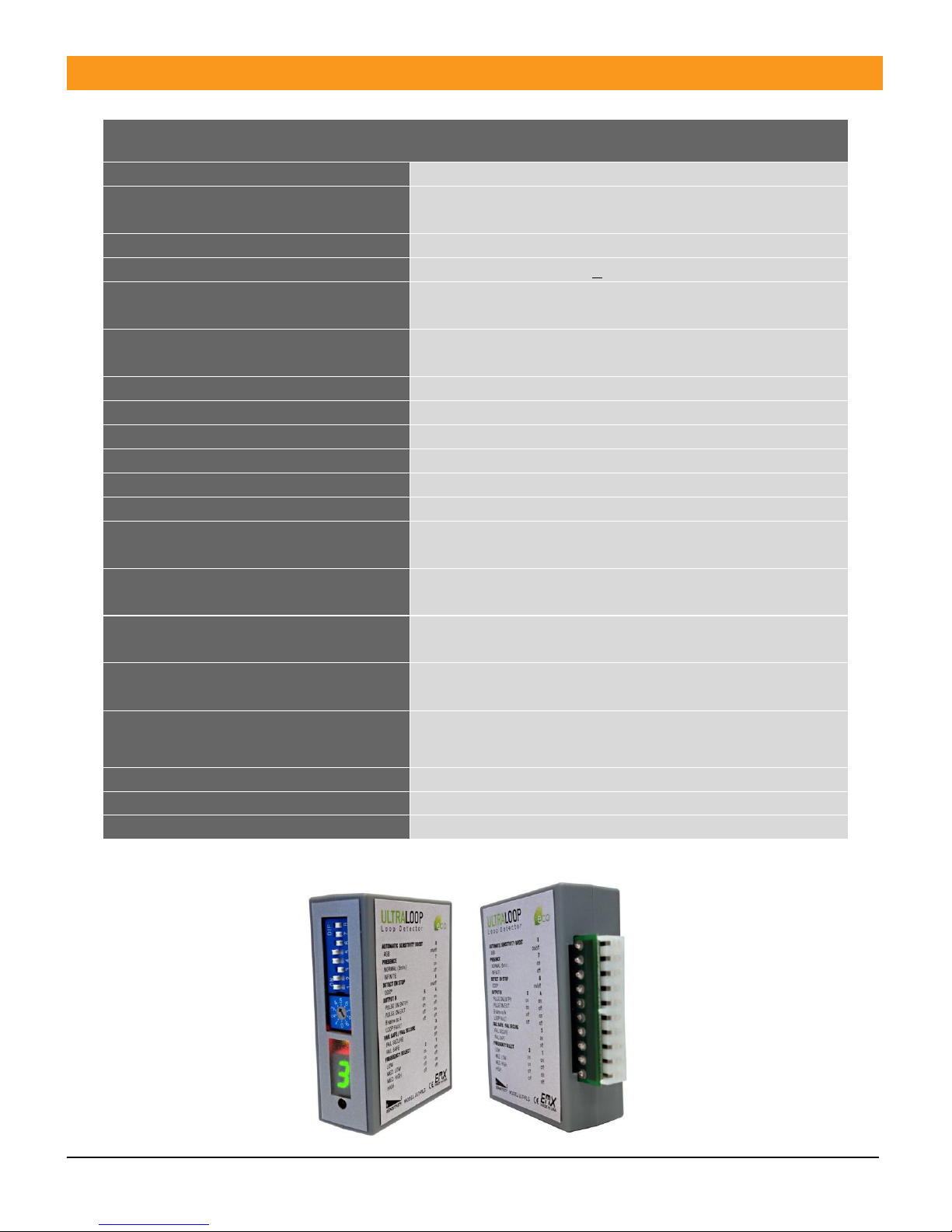
Controls and Indicators
AUTOMATIC SENSITIVITY BOOST
PRESENCE
DETECT-ON-STOP (DOS)
OUTPUT B
(1) Not used when DOS is selected
FAIL SAFE / SECURE
FREQUENCY SETTINGS
SENSITIVITY SETTING
DETECT / FREQUENCY COUNT
ULTRAMETER™ DISPLAY
Indicates sensitivity setting required to detect vehicle
FREQUENCY COUNT / RESET
Press to start frequency count, re-initializes after count
DIP switch position 8
ASB enabled
on
DIP switch position 7
NORMAL (5 min.)
on
INFINITE
off
DIP switch position 6
DOS on
on
DOS off
off
DIP switch position
MODE
4
5
Pulse on Entry
on
on
Pulse on Exit(1)
off
on
B same as A
on
off
Loop Fault
off
off
DIP switch position 3
Fail Secure
on
Fail Safe
off
DIP switch position
FREQUENCY
2
1
Low
on
on
Medium low
on
off
Medium high
off
on
High
off
off
Position 0…….9
Sensitivity
Low……….high
Red LED
Presence detected
on
No presence
off
Frequency count
flashing

ULT-PLG™ Operating Instructions 7
Document no. 10180904
Connections
Connector pin
Description
1
Loop
2
Loop
3
Power + (12VDC…24VDC)
4
No connection
5
No connection
6
Output B
7
Output B inverted
8
Presence output
9
Power + (12VDC…24VDC)
10
Common

ULT-PLG™ Operating Instructions 8
Document no. 10180904
Troubleshooting
Symptom
Possible cause
Solution
Green LED flashes
Loop wire shorted or open
Check loop resistance on the
appropriate loop pins on the
control board connector,
between .5 ohms and 5 ohms.
Green LED flashes, 2 fast
Loop was previously
shorted or open
Check loop resistance on the
appropriate loop pins on the
control board connector.
Detector remains in
detect after vehicle has
left loop
1. Faulty loop
2. Poorly crimped
terminals
3. Loose connections
1. Perform megger test from
loop lead to ground, should
be >100 megaohms
2. Check loop connections to
terminals
3. Check splices are properly
soldered and sealed against
moisture
4. Observe ULTRAMETER
display, level indicated on
display indicates residual
frequency shift from vacant
loop to vehicle presence,
press Frequency Count switch
to re-initialize the detector
Intermittent detection
1. Faulty loop
2. Poorly crimped
terminals
3. Loose connections
4. Cross-talk between
adjacent loops
1. Perform megger test from
loop lead to ground, should
be >100 mega ohms
2. Check loop connections to
terminals
3. Check splices are properly
soldered and sealed against
moisture
4. Set adjacent loops to
different frequencies (see
Frequency Setting)
No detection
1. Loop wire shorted or
open
2. Loop sensitivity set too
low
1. Check loop resistance on the
appropriate loop pins on the
control board connector,
between .5 ohms and 5
ohms.
2. With vehicle on loop, observe
ULTRAMETER display, set
sensitivity to the level
indicated on the display
ULT-PLG™ Operating Instructions 9
Document no. 10180904
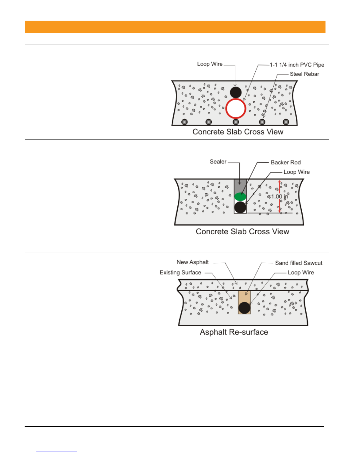
Loop Installation
NEW SLAB POUR
Ty-wrap 1-1/4” PVC pipe to the top of the
rebar in the size and configuration of the
loop (ex. 4’ x 8’). Then ty-wrap the loop to
the top of the PVC frame. This stabilizes the
loop during the pour and separates it from
the rebar.
SAW CUT EXISTING SURFACE
Cut 1” deep into the existing surface, place
a 45° cut at the corners to prevent sharp
edges from damaging the loop wire. Notch
out for the “T” connection where the lead
wire connects to the loop. Remove all
debris from the finished cut with
compressed air. Place the loop into the
saw cut. Place backer material into the saw
cut over the loop wire and pack tightly.
Place a high-quality sealer over the saw cut
to seal the surface.
RESURFACE ASPHALT
Saw cut the existing surface ¾” deep and
place a 45° cut at the corners to prevent
sharp edges from damaging the loop wire.
Remove all debris from the finished cut
with compressed air. Place sand over the
loop wire to the surface and pack tightly.
Lay new asphalt.
General Installation Guidelines
Use EMX Lite Preformed loops for quick, reliable installations and for CE compliance.
Lead-in wire (wire from loop to detector) must be must be twisted a minimum of 6 turns/ foot
to avoid the effects of noise or other interference.
Detection height is approximately 70% of the shortest side of the loop. Example: detection
height for an 4’ x 8’ loop = 48” x .7 = 33.6”

ULT-PLG™ Operating Instructions 10
Document no. 10180904
Ordering Information
ULT-PLG Ultra PLG Vehicle Loop Detector with DIN rail mounting
Accessories
PR-XX EMX Lite Preformed Loops™
Warranty
EMX Industries Incorporated warrants all products to be free of defects in
materials and workmanship for a period of two years under normal use and
service from the date of sale to our customer. This warranty does not cover
normal wear and tear, abuse, misuse, overloading, altered products, damage
caused by incorrect connections, lightning damage, or use other than intended
design.
There is no warranty of merchantability. There are no warranties expressed or
implied or any affirmation of fact or representation except as set forth herein.
EMX Industries Inc. sole responsibility and liability, and the purchaser’s
exclusive remedy shall be limited to the repair or replacement at EMX
Industries option of a part or parts found not conforming to the warranty. In
no event shall EMX Industries Inc. be liable for damages, including but not
limited to damages resulting from non-conformity, defect in material or
workmanship.
Effective date: January 1st, 2002

ULT-PLG™ Operating Instructions 11
Document no. 10180904
BLANK PAGE

ULT-PLG™ Operating Instructions 12
Document no. 10180904
BLANK PAGE

ULT-PLG™ Operating Instructions 13
Document no. 10180904
4564 Johnston Parkway
Cleveland, Ohio 44128
United States of America
www.emxinc.com
Technical Support: (216) 834-0761
Sales: (216) 518-9888
Fax: (216) 518-9884
Revision 1.4
3.12.2018
Table of contents
Other EMX Industries, Inc. Security Sensor manuals

Popular Security Sensor manuals by other brands


Memco
Memco 618 Installation sheet

Elko
Elko iNELS Air AirKey quick start guide

LEGRAND
LEGRAND Mosaic 0 489 22 manual

DMP Electronics
DMP Electronics 1128 installation guide

Honeywell
Honeywell 5800COMBO Installation and setup guide

System Sensor
System Sensor AFD Accuflow Installation and maintenance instructions

Sentrol
Sentrol 5150-W - Security Glassbreak Shock Sensor installation instructions

Wenglor
Wenglor IR2D001 operating instructions

Smartenit
Smartenit ZBMS3 quick start guide

Bullard
Bullard H3000 Installation instruction

BST
BST Flamonitec IFR 400 operating manual

Antec Scientific
Antec Scientific DECADE II SDC 174 user manual