EMX IRB-EXP User manual
EMX Industries, Inc. Tech support: 216-518-9889 1/3
IRB-EXP_Rev2.1_061620 [email protected]
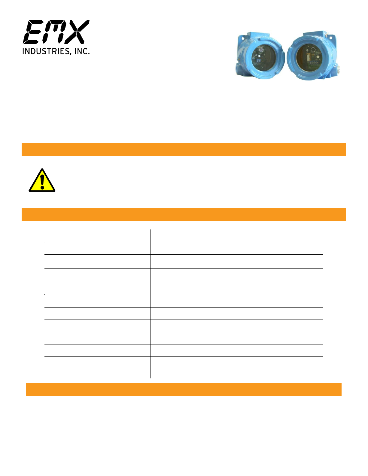
IRB-EXP™
Explosion-Proof Photoeye
Instruction Manual
Designed for explosive environments, the rugged IRB-EXP thru beam photoeye is used as a safety,
reversing or opening device with automatic gate and door operators. The photoeye provides a signal to
the operator that the beam is or is not obstructed. The IRB-EXP operates up to 115 feet in a cast aluminum
housing. A red alignment indicator on the receiver provides status information at a glance, making set-up
and alignment easy.
This product is an accessory or part of a system. Install the IRB-EXP according to
instructions from the gate or door operator manufacturer. Comply with all applicable
codes and safety regulations.
Ordering Information
•IRB-EXP Explosion-Proof Photoeye
Cautions and Warnings
Specifications
Operating Range
Up to 115 ft. (35 m)
Power
12-24 VDC/AC
Current Draw of Transmitter
37 mA
Current Draw of Receiver
23 mA standby, 17 mA detect
Surge Protection
Thermal fuse
Relay Output Configuration
Form C contacts (NO, COM, NC)
Relay Contact Rating
1 A at 24 VDC / 120 VAC
Operating Temperature
-40° to 170°F (-40° to 77°C)
Housing Material
Cast aluminum
Dimensions (L x W x H)
3.4” (87 mm) x 4.5” (114 mm) x 4.7” (119 mm)
Environmental Rating
NEMA 4 & 7, NEC Class 1 Groups B, C, & D,
NEC Class II Groups E, F & G, CSA CENELEC, EExd IIC
TM

Installation
1. Remove the plastic and threaded plugs from both sides of the housing. Determine which direction
the conduit will enter the housing and insert the threaded plug on the opposite side.
2. Connect 12-24 VDC/AC power to the “Power Input” terminals on the transmitter (marked “TX”)
and receiver (marked “RX”). The power input terminals are not polarity sensitive.
3. Connect the Common (COM) to the control input terminal per the operator manufacturer.
4. Connect either the Normally Open (NO) or Normally Closed (NC) as needed to the control input
terminal per the operator manufacturer.
5. Adjust the sensitivity potentiometer as needed by turning counter clockwise to increase gain.
Use the minimum sensitivity setting needed to achieve reliable detection.
6. Verify that the IRB-EXP transmitter and receiver are aligned and apply power.
LED Indicators
Green transmitter LED on
Power
Green receiver LED on
Power
Red receiver LED on
Beam blocked or not aligned
7. Place an obstruction (ex. hand) between the IRB-EXP transmitter and receiver. The red LED on the
receiver will turn on. Check the operator control board and verify that the safety input is recognized
by the operator. Test the beam with an obstruction between the transmitter and receiver at
multiple distances to confirm proper operation.
8. Remove the obstruction and red LED will turn off.
•If IRB-EXP is aligned but not detecting an obstruction, consider slowly reducing
the sensitivity (clockwise) on the receiver until the obstruction is detected.
This may be applicable for installations with a detection zone of less than 20 ft.
Board Diagram
TIP:

Symptom
Possible Cause
Solution
Does not detect obstruction
Sensitivity is too high
Signal is reflecting off another
surface
Decrease sensitivity
potentiometer clockwise.
Check area for highly reflective
surfaces.
Receiver red LED on
continuously, indicating an
obstruction when one is not
present
Sensitivity is too low
Transmitter does not have
power
Receiver does not “see”
transmitter
Increase sensitivity
potentiometer counter -
clockwise.
Check power source of
transmitter.
Make sure transmitter and
receiver are aligned.
Receiver activates but does not
transmit signal to operator
Faulty connection between
receiver and operator control
input
Verify all wires and terminal
connections.
EMX Industries, Inc. products have a warranty against defects in materials and workmanship for a period
of two years from date of sale to our customer.
Troubleshooting
Warranty
Other EMX Accessories manuals


