EMX IRB-4X User manual
O P E R A T I N G I N S T R U C T I O N S
Operating Instructions
4564 Johnston Parkway, Cleveland, Ohio 44128
P. 800 426 9912 F. 216 518 9884
www.emxinc.com
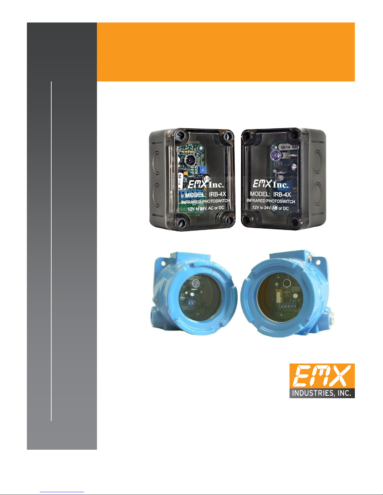
IRB-4X™
INCLUDES MODEL IRB-EXP
T H R U B E A M PH O T O E Y E
U L 3 2 5 N O N - CO M P L I A N T
IRB-EXP (for explosive environments)

IRB-4X™ Operating Instructions 1
Document no. 10060104
Contents
Cautions and Warnings
2
Product Overview
2
Specifications
3
Controls and Indicators
4
Connections
4
Operational Settings
5
Troubleshooting
6
Installation
7
Ordering Information
8
Accessories
8
Warranty
9
IRB-4X™ Operating Instructions 2
Document no. 10060104
Cautions and Warnings
IMPORTANT:
This product is an accessory or part of a system. Always read and follow the
manufacturer’s instructions for the equipment before connecting this product.
Comply with all applicable codes and safety regulations. Failure to do so may
result in damage, injury or death.
WARNING ... Not to be used for Personnel Protection
Never use product as sensing devices for personnel protection. Doing so could cause serious
injury or death. These sensors do NOT include the self-checking redundant circuitry necessary
to allow their use in personnel safety applications. A sensor failure or malfunction can cause
either an energized or de-energized sensor output condition. UL 325 Non-compliant
Product Overview
The IRB-4X is used as a safety, reversing, or opening device when used in conjunction with automatic
operators, garage doors, rolling doors and parking barriers. Its generous 24osensing angle makes this
reliable photoeye easy to align. The use of the hoods is recommended to prevent distortion from rain
on the lens area.

IRB-4X™ Operating Instructions 3
Document no. 10060104
Specifications
Specifications
Power Supply
12-24 VDC, 24 VAC
Power Supply Tolerance
20%
Current Draw
TX = 37mA RX = 23mA standby 17mA detect
Housing Material
Polystyrene and Polycarbonate cover
IRB-EXP aluminum epoxy coating
Relay Type
Form C SPDT contact rating 1A @ 24VDC / 120VAC
Temperature Range
-40F –170F
Connector
Terminal block
Power on Indicator
Green LED on board
Detect Indicator
Red LED
Power Protection
Thermal fuse
Environmental
IRB-4X: NEMA 4
IRB-EXP: NEMA 4 & 7, NEC Class 1, Groups B, C, & D,
Class II, Groups E, F, & G CSA certified,
CENELEC certified, EExd IIC
Size
IRB-4X: 3.7” x 2.56” x 2.24”
IRB-EXP: 4.69” x 4.5” x 3.44”
Detection Angle
24 o
Sensitivity Adjustment
Potentiometer
Response Time
10mS (max.)
Range
3 to 115 feet

IRB-4X™ Operating Instructions 4
Document no. 10060104
Controls and Indicators
Indicators Controls
Transmitter Receiver
Receiver
Connections
Transmitter
Receiver
Power
Power Positive(+)
Power Positive(+)
Power
Power Negative(-)
Power Negative(-)
Common
Internal Relay Common Output
Normally Closed
Internal Relay Normally Closed Output
Normally Open
Internal Relay Normally Open Output
Terminal Connection on receiver from left to right are N/C, Com, N/O, Power -, Power +
Sensitivity
Continuously adjustable single
turn potentiometer figure 2
(1)IRB-4X-T has a 0 –15 second
relay timer to extend the relay
output time figure 2
Green LED
Power Indicator
Green LED
Power Indicator
Red LED
Detection Indication
IRB-4X™ Operating Instructions 5
Document no. 10060104
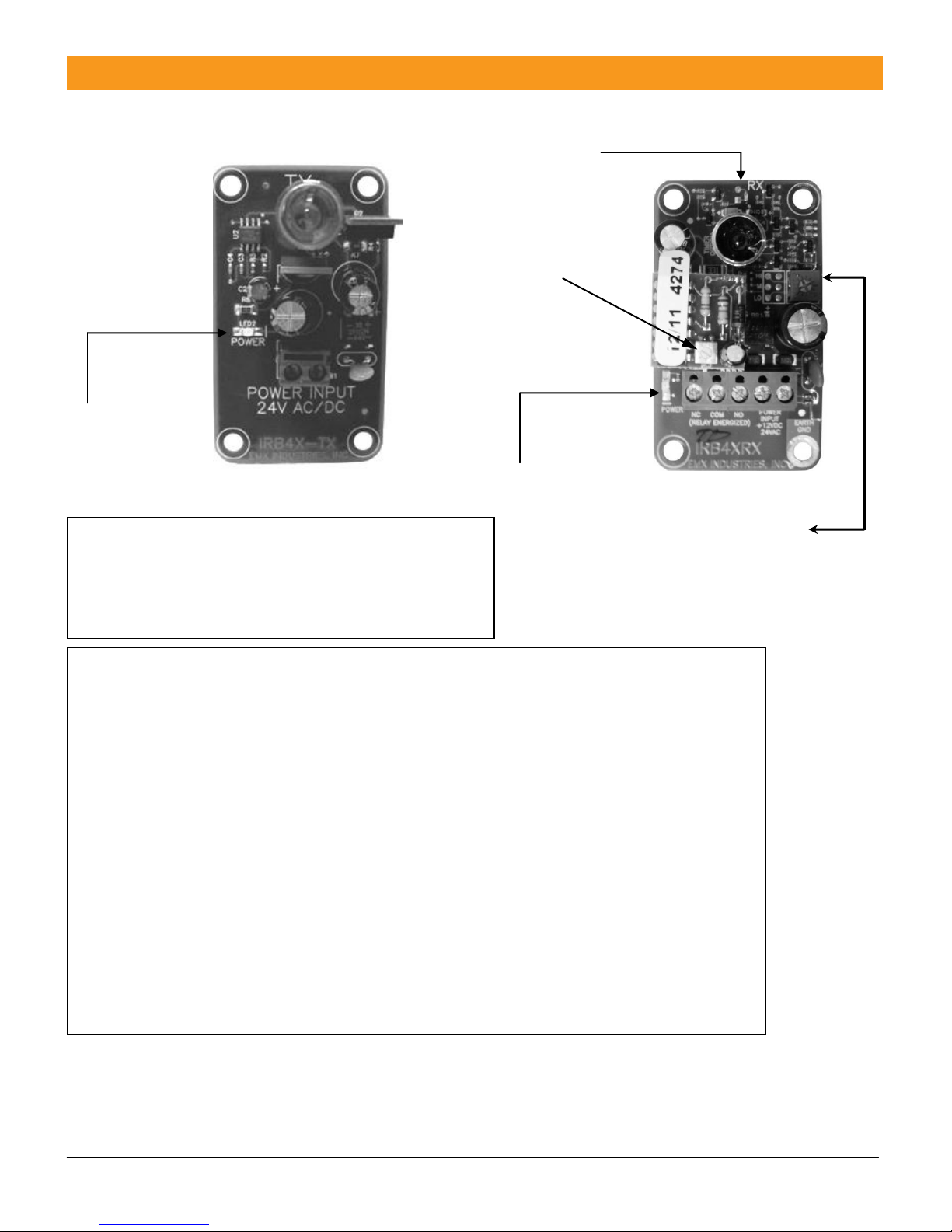
IRB-4X Transmitter connections (figure 1)
1. Connect power (12 –24V AC/DC) to Power
input terminals (no polarity) LED2 Power LED will
glow green when powered.
IRB-4X Receiver connections (figure 2)
Terminal output connections from left to right are:
Normally closed, Common, Normally open, Power, Power
1. Connect power (12 –24V AC/DC to Power input terminals (no polarity)
2. Connect the Common to the operator control terminal per manufacturer
3. Connect either the Normally open or Normally Closed as needed to the
Control input terminal specified by the operator manufacturer.
4. The Power LED will glow green when powered.
5. Adjust sensitivity potentiometer as needed by turning counter clockwise
to increase gain. (range is 3 to 115 feet). (see arrow)
6. The detect Led will glow red when an obstruction occurs.
7. On some variable frequency drives and noisy installations, it may be necessary
to connect the bottom right mounting hole labeled
“Earth Ground” to a wire connected to earth ground.
* Do not connect unless necessary
Use minimum gain setting needed to achieve reliable detection.
Operational settings
Detect LED
Optional output
timer delay order
IRB-4X-T
Note (1) IRB-4X-T
has been discontinued
Power LED
Figure 1 Power LED Figure 2
Sensitivity Gain Adjustment

IRB-4X™ Operating Instructions 6
Document no. 10060104
Troubleshooting
Symptom
Possible cause
Solution
Holds gate open
1. No power on transmitter
or receiver
2. Transmitter not working
3. Receiver not working
4. Sensitivity set too low
1. Check power LEDs and power source
2. Install new transmitter
3. Install new receiver
4. Adjust sensitivity
Does not
activate gate
1. Bad connection or broken
wires
2. Relay contacts burned or
stuck
3. Interference from local
source
4. Not Connected to correct
input terminals
5. Sunlight “blinding” the
receiver eye
1. Check wires and connections
2. Replace Receiver
3. See step 7 under Operational Settings
4. Check operator manual for terminals
5. Change position of receiver to a little
higher and tilt forward to shield the
sensor from the direct sunlight
Chattering
1. Interference
See step 7 under Operational settings
and see if any reflective surfaces could
be sending a signal into the receiver
sensor
IRB-4X™ Operating Instructions 7
Document no. 10060104
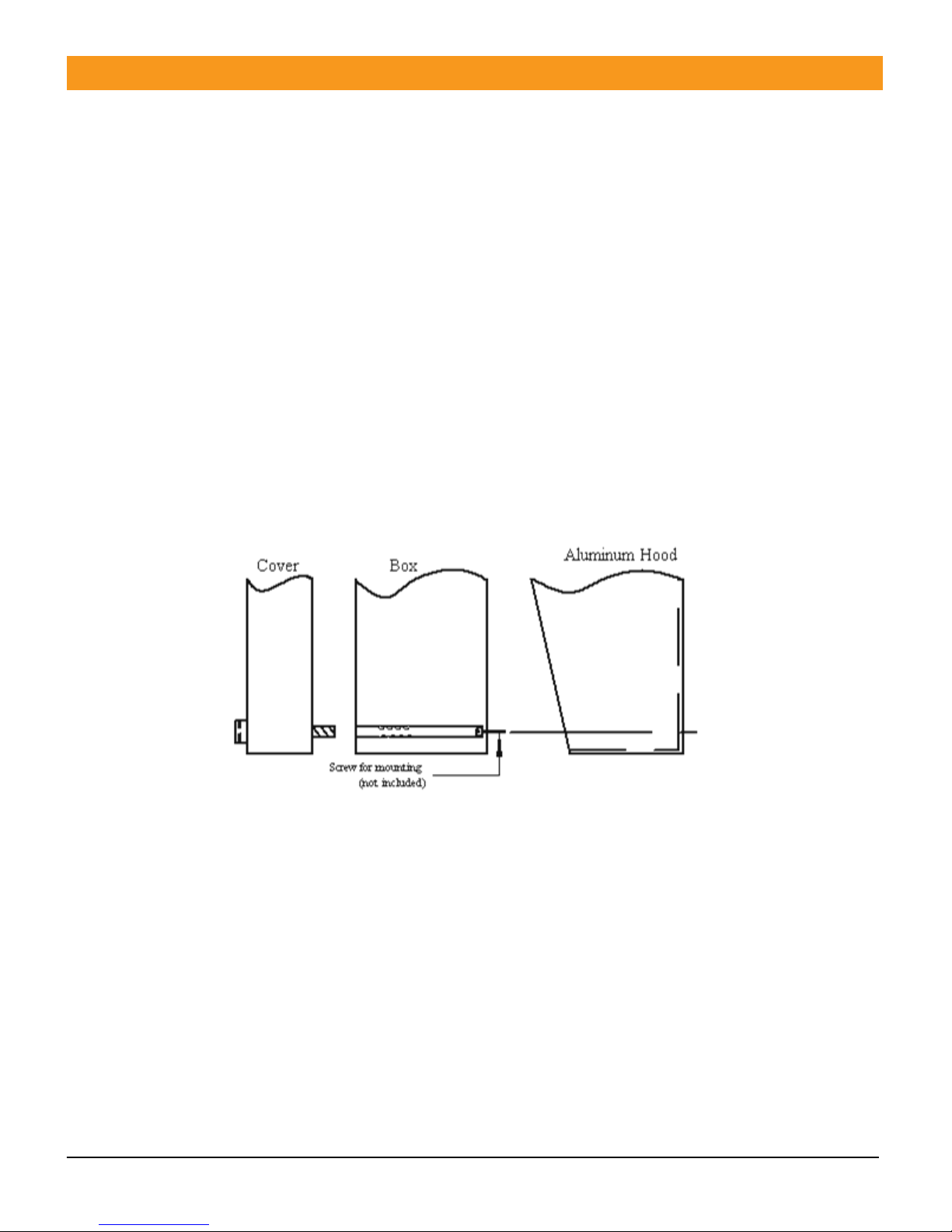
Installation
1. Mount to operator manufacturer and local ordinance requirements.
2. Remove grey front cover by removing (4) plastic retaining screws
3. Drill (4) mounting holes in surface of IRB-4X mounting location.
4. Place gold Aluminum hood or Powder coat Steel hood around IRB-4X unit to be mounted, place
mounting screws through IRB-4X box and hood and attach to surface.
5. Make all connections to the transmitter and receiver.
6. Adjust receiver as described above to correct gain needed.
7. Replace front covers on the transmitter and receiver units.
8. Installation is complete.

IRB-4X™ Operating Instructions 8
Document no. 10060104
Ordering Information
IRB-4X IRB Transmitter and Receiver in NEMA 4 enclosure
IRB-BX Replacement NEMA Enclosure
IRB-SP Set of 2 watertight spouts PG-11
IRB-TX Replacement Transmitter board only
IRB-RX Replacement Receiver board only
IRB-BR Set of 2 L Brackets
IRB-HD-SET Set of 2 Gold Aluminum hoods
IRB-SH-SET Set of 2 Gray Powder coated steel hoods
IRB-S Set of 2 Nylon screws with nuts
IRB-EXP IRB Transmitter and Receiver in Explosive environment housing
This manual covers the IRB-4X and IRB-EXP models.
OBSOLETE PRODUCTS
IRB-4X-T IRB Transmitter and Receiver in NEMA 4 enclosure with delay timer
IRB-4X-T, IRB-4XW-T, IRB-4XW-T5
Accessories
IRB-HD-SET Protective hood, aluminum, gold anodized
IRB-SD-SET Protective hood, steel, gray powder-coat
IRB-BR Mounting bracket, “L” shape
IRB-SP Strain relief, water-tight
IRB-S Nylon screws, set of 2 with nuts

IRB-4X™ Operating Instructions 9
Document no. 10060104
Warranty
EMX Industries Incorporated warrants all products to be free of defects in
materials and workmanship for a period of two years under normal use and
service from the date of sale to our customer. This warranty does not cover
normal wear and tear, abuse, misuse, overloading, altered products, damage
caused by incorrect connections, lightning damage, or use other than intended
design.
There is no warranty of merchantability. There are no warranties expressed or
implied or any affirmation of fact or representation except as set forth herein.
EMX Industries Inc. sole responsibility and liability, and the purchaser’s
exclusive remedy shall be limited to the repair or replacement at EMX
Industries option of a part or parts found not conforming to the warranty. In
no event shall EMX Industries Inc. be liable for damages, including but not
limited to damages resulting from non-conformity, defect in material or
workmanship.
Effective date: January 1st, 2002

IRB-4X™ Operating Instructions 10
Document no. 10060104
BLANK PAGE

IRB-4X™ Operating Instructions 11
Document no. 10060104
4564 Johnston Parkway
Cleveland, Ohio 44128
United States of America
www.emxinc.com
Technical Support: (216) 834-0761
Sales: (216) 518-9888
Fax: (216) 518-9884
Revision 1.7
2.28.18
Other manuals for IRB-4X
1
This manual suits for next models
1
Table of contents
Other EMX Accessories manuals


Popular Accessories manuals by other brands

turck
turck FCS-G3/4A4-NAEX0-H1141 manual

Sentera Controls
Sentera Controls FCMFFB-R Mounting and operating instructions

Rice Lake
Rice Lake MSI-8000HD Technical manual

Novalynx
Novalynx 200-WS-02 Series user manual

AVK
AVK 3001/004 Installation, operation and maintenance manual

Axor
Axor Citterio 41730XX0 parts list


