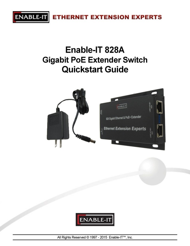
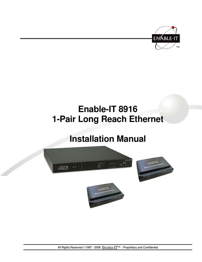
Enable-IT 8440 User manual

All Rights Reserved ©1997 - 2015 ENABLE-IT™- Proprietary and Confidential
Copyright © 1997-2015 Enable-IT, Inc. All rights reserved. No part of this documentation
may be reproduced in any form or by any means or used to make any derivative work (such
as translation, transformation, or adaptation) without written permission from Enable-IT, Inc.
Enable-IT, Inc. reserves the right to revise this documentation and to make changes in
content from time to time without obligation on the part of Enable-IT, Inc to provide
notification of such revision or change.
Enable-IT, Inc. provides this documentation without warranty, term, or condition of any kind,
either implied or expressed, including, but not limited to, the implied warranties, terms or
conditions of merchantability, satisfactory quality, and fitness for a particular purpose.
Enable-IT, Inc may make improvements or changes in the product(s) and/or the program(s)
described in this documentation at any time.
If there is any software on removable media described in this documentation, it is furnished
under a license agreement included with the product as a separate document, in the hard
copy documentation. If you are unable to locate a copy, please contact Enable-IT, Inc. and a
copy will be provided to you.
UNITED STATES GOVERNMENT LEGEND
If you are a United States government agency, then this documentation and the software
described herein are provided to you subject to the following:
All technical data and computer software are commercial in nature and developed solely at
private expense. Software is delivered as "Commercial Computer Software" as defined in
DFARS 252.227-7014 (June 1995) or as a "commercial item" as defined in FAR 2.101 (a)
and as such is provided with only such rights as are provided in Enable-IT, Inc's standard
commercial license for the Software.
Technical data is provided with limited rights only as provided in DFAR 252.227-7015 (Nov
1995) or FAR 52.227-14 (June 1987), whichever is applicable. You agree not to remove or
deface any portion of any legend provided on any licensed program or documentation
contained in, or delivered to you in conjunction with, this User Guide.
Unless otherwise indicated, Enable-IT, Inc registered trademarks are registered in the United

Enable-IT 8440 Wireless
Access Point Router
User Manual!
!
!
!
All Rights Reserved ©1997 - 2015 Enable-IT, Inc. Page !of !218

CONTENTS
ABOUT THIS GUIDE 4
PRODUCT OVERVIEW 5
PACKAGE CONTENTS 5
SYSTEM REQUIREMENTS 5
TOP VIEW 5
REAR VIEW 6
HARDWARE INSTALLATION 6
CONNECTING AWIRELESS CLIENT TO THE AIRROUTER 9
NAVIGATION 10
MAIN 11
STATUS 12
MONITOR 13
THROUGHPUT 13
STATIONS 14
STATION INFO 14
AP INFORMATION 15
TECHNICAL SUPPORT 16
RETURNING PRODUCTS FOR WARRANTY REPAIR 16
ENABLE-IT LIMITED WARRANTY 16
CONTACT US 18
All Rights Reserved ©1997 - 2015 Enable-IT, Inc. Page !of !318

ABOUT THIS GUIDE
This guide provides all the information needed to install and use the Enable-IT
8440 Wireless Access Point Router. This guide is intended for use by technicians
who are responsible for installing and setting up network equipment.
Consequently, it is assumed that the installer has a basic working knowledge of
LANs (Local Area Networks) and voice telecom wiring.
If the information in the release notes that are shipped with your product differs
from the information in this guide, follow the instructions in the release notes.
Most user guides and release notes are available in Adobe Acrobat
Reader Portable Document Format (PDF) or HTML on the Enable-IT World Wide
Web site: http://www.ethernetextender.com/manuals/8440Manual.pdf!
All Rights Reserved ©1997 - 2015 Enable-IT, Inc. Page !of !418

PRODUCT OVERVIEW
Thank you for purchasing the Enable-IT 8440 Wireless Access Point Router!
Package Contents
System Requirements
•Microsoft Windows XP, Windows Vista, Windows 7, Linux, or Mac OS X
•Java Runtime Environment 1.6 (or above) for the AirView utility
•Web Browser: Mozilla Firefox, Apple Safari, or Microsoft Internet Explorer
Top View
All Rights Reserved ©1997 - 2015 Enable-IT, Inc. Page !of !518
Enable-IT 8440 Power Adapter Ethernet Cable Quickstart Guide

Rear View
Hardware Installation
1. Connect the power adapter to the port labeled Power on the Enable-IT 8440.
Connect the other end of the power adapter to a power outlet.
All Rights Reserved ©1997 - 2015 Enable-IT, Inc. Page !of !618

2. Connect an Ethernet cable to Ethernet port 1.
3. Connect the other end of the Ethernet cable to your computer.
4. Launch your Web browser and type http://192.168.1.1 in the address field and press
enter (PC) or return (Mac).
All Rights Reserved ©1997 - 2015 Enable-IT, Inc. Page !of !718

5. The login screen will appear. Enter ubnt in the Username and Password fields and
click login.
6. The AirOS interface will
appear. Go to the Wireless tab.
7.Customize your
wireless network and secure your network by entering the basic wireless network
information:
•Enter a name for
All Rights Reserved ©1997 - 2015 Enable-IT, Inc. Page !of !818

your wireless network in the SSID field.
•Select the type of security that you want to use for your wireless network from
the Security drop-down.
•Enter a passphrase in
the WPA Preshared Key field. You can click the Show option to see the
characters that you are typing.
•Click Change. You will be prompted to apply the changes. To proceed, click
Apply.
8. If necessary, disconnect the power and Ethernet cables to move the router so that you
can connect it to your Internet connection.
9. Connect an Ethernet cable from your broadband modem or other Internet connection
to the port labeled ßà on the back of the Enable-IT 8440.
Now you basic router installation
is complete. Next step is connecting a wireless client to the Enable-IT 8440 Router.
Connecting a Wireless Client to the Enable-IT 8440 Wireless Router
Windows
1. Go to Connect to Network.
•Windows 7 Right-click on the Network icon.
•Windows Vista Go to Start > Connect To.
•Windows XP Right-click the Wireless Network icon in the System Tray (lower
right corner of the screen) and then click View Available Wireless Networks.
2. Select the wireless network (SSID) that you entered in the SSID field in step 7 bullet
point 1 and then click Connect.
3. Type the passphrase that you entered in the WPA Preshared Key field in step 7 bullet
point 3 and click OK or Connect.
4. Launch your web browser to begin browsing the web.
All Rights Reserved ©1997 - 2015 Enable-IT, Inc. Page !of !918

Mac
1. Click the AirPort icon in the menu bar (top side of the screen).
2. Select the wireless network (SSID) that you entered in the SSID field in step 7 bullet
point 1.
3. Type the passphrase that you entered in the WPA Preshared Key field in step 7 bullet
point 3 and click OK.
4. Once connected the AirPort!icon will change from gray to solid black. The number
of black lines indicates the signal strength. Launch your web browser to begin
browsing the web.
AirOS™
AirOS™ is an advanced operating system that is capable of powerful wireless and
routing features. AirOS is built upon a simple and intuitive user interface. AirOS allows you to
maximize the wireless performance of Enable-IT products which are based on IEEE
802.11af.
To access the interface, perform the folling steps:
1. Launch your Web browser and type http://192.168.1.1 in the address field and press
enter (PC) or return (Mac).
2. The login screen will appear.
Enter ubnt in the Username and Password field and click Login.
Navigation
The interface contains six main tabs:
•Main The Main tab displays AirRouter status information and provides network
monitoring links.
•Wireless The Wireless tab allows you to configure the wireless mode, the basic
wireless settings and the wireless security settings for the AirRouter.
•Network The Network tab covers the configuration of the network operating mode, IP
settings, packet filtering routines and network services.
•Advanced The Advanced tab settings are available for additional wireless interface
controls. The AirMax feature and advanced wireless settings can be configured in this
tab. The Advanced tab also includes advanced Ethernet and traffic shaping settings.
•Services The Services tab contains controls for system management services like
SNMP, NTP, System Log, Ping Watchdog and SSH/Telnet server.
All Rights Reserved ©1997 - 2015 Enable-IT, Inc. Page !of !10 18

•System The System tab contains controls for system maintenance routines,
administrator account management, device customization, firmware upgrade and
configuration backup. The interface language can also be selected here.
Each page also contains network administration and monitoring tools.
•Align Antenna
•Site Survey
•Ping
•Traceroute
•Speed test
•AirView
Main
The Main tab displays a summary of the link status information, current values of the basic
configuration settings (depending on the operating mode), network settings and information,
and traffic statistics.
Status
Device Name Displays the
customizable name (ID) of the 8440 Router. The Device Name (Host Name) is displayed in
registration screens and discovery tools.
All Rights Reserved ©1997 - 2015 Enable-IT, Inc. Page !of !11 18

Network Mode Displays the network mode that the 8440 Router is operating in. There are three
modes available: Bridge, Router, and SOHO router. SOHO router is the default setting. This setting
is configured on the Network tab.
Wireless Mode Displays the radio interface operating mode. Access Point (or Access Point WDS)
and Station (or Station WDS) operating modes can be set depending on the network topology
requirements.
SSID Displays the wireless network name (SSID). The wireless network name is dependent upon
the wireless mode selected:
•While operating in Station mode, displays the SSID of the Access Point the 8440 Router is
associated with.
•While operating in Access Point mode, this displays the SSID configured on the 8440 Router.
The SSID is configured on the Wireless tab.
Security Displays the wireless security method being used on the 8440 Router. If None is
displayed, then wireless security has been disabled.
Version displays the version of the AirOS software.
Uptime This is the total time the 8440 Router has been running since last power up (reboot) or
software upgrade. The time is displayed in days, hours, minutes and seconds.
Date Displays the current system date and time. The date and time are displayed in YEAR-
MONTH-DAY-HOURS:MINUTES:SECONDS format. The system date and time is retrieved from the
Internet using NTP (Network Time Protocol). NTP Client is enabled by default on the Services tab.
The 8440 Router doesn’t have an internal clock and the date and time may be inaccurate in NTP
Client is disabled or not connected to the Internet.
Channel/Frequency Displays the channel number and corresponding operating frequency. The
8440 Router uses the channel/radio frequency specified to transmit and receive data. Valid channel/
frequency range will vary depending on local country regulations.
Channel Width This is the spectral width of the radio channel used by the 8440 Router. 5,10,20
and 40 MHz channel spectrum widths are supported. In Station (or Station WDS) 20/40 MHz is the
value by default.
ACK/Distance Displays the current timeout value for ACK frames. ACK Timeout can be set
manually or self-adjusted automatically. The ACK Timeout (Acknowledgement frame Timeout)
specifies how long the 8440 should wait for an acknowledgement from a partner device confirming
packet reception before concluding there must have been an error and resending the packet.
TX/RX Chains Displays the number of independent spatial data streams the 8440 Router is
transmitting/ receiving simultaneously within one spectral channel of bandwidth. This ability is
specific for 802.11n devices which rely on multiple-input multiple-output MIMO) technology. Multiple
chains increase data transfer performance significantly. Every TX/RX chain requires a separate
antenna.
WLAN MAC Displays the MAC address of the 8440 Router as seen on the wireless network.
LAN MAC Displays the MAC address of the 8440 Router as seen on the LAN (Local Area
Network).
WAN MAC Displays the MAC address of the 8440 Router as seen on the WAN interface. This is
the 8440 Router’s MAC address that is seen over the Internet.
All Rights Reserved ©1997 - 2015 Enable-IT, Inc. Page !of !12 18

WAN/LAN Indicates the current status of the WAN and LAN Ethernet port connections. This can
indicate that a cable is not plugged into a device and there is no active Ethernet connection.
AP MAC Displays the MAC address of the 8440 Router in Access Point or Access Point WDS
mode. In Station or Stations WDS mode, the displays the MAC address of the Access Point the
8440 Router is associated with.
Connections Displays the number of wireless devices connected to the 8440 when the device is
operating in Access Point or Access Point WDS mode. This value is not displayed while operating in
Station of Station WDS mode.
Noise Floor Displays the current value of the noise level in dBm. Noise Floor is taken into account
while evaluating the signal quality (Signal-to-Noise SNR, RSSI).
Transmit CCQ This is an index of which evaluates the wireless Client Connection Quality. The level
is based on a percentage value where 100% corresponds to a perfect link state.
TX Rate and RX Rate Displays the current 802.11 data transmission (TX) and data reception (RX)
rate when operating in Station or Station WDS mode.
Airmax Indicates the AirMax status when operating in Access Point of Access Point WDS mode. If
AirMx is enabled, the 8440 Router will only accept Air Max clients. (Disable AirMax for legacy
802.11bgn device compatibility). AirMax also features advanced QoS Autodetection settings.
Airmax Quality This displays the AirMax Connection Quality. The level is based on a percentage
value where 100% corresponds to a perfect link state.
Airmax Capacity This is an index of maximum data rate the link is operating at. A lower Capacity
number indicates a unit that is bogging the system down.
Monitor
There are various monitoring tools accessible via the links on the Main tab. The default selection is
Throughput which is displayed as soon as you open the Main tab.
Throughput
Shows a visual
representation of the current data traffic on the LAN and WLAN in both graphical and numerical
form. The chart scale and throughput dimension (Bps, Kbps, Mbps) changes dynamically according
to the mean throughput value. The statistics can be updated manually using the Refresh button.
All Rights Reserved ©1997 - 2015 Enable-IT, Inc. Page !of !13 18

Stations
This selection lists the stations which are connected to the 8440 Router while operating in Access
Point or Access Point WDS mode.
The following
statistics for each station are displayed in the station statistics window:
Station MAC MAC address of the associated station. This is a clickable link that will display
additional station info.
Device Name Displays the client’s host name (if defined).
Signal/Noise, dBm Signal value represents the last received wireless signal level, and Noise
displays the value of the noise level.
Tx/Rx, Mbps Tx value represents the data rates, in Mbps, of the last transmitted packets, and Rx
value represents the data rates, in Mbps, of the last received packets.
CCQ, % This is an index that evaluates the wireless Client Connection Quality (CCQ). The level is a
percentage value where 100% corresponds to a perfect link state.
Connection Time Displays the connection time of each station connected to the 8440 Router. The
time is expressed in days, hours, minutes and seconds.
Last IP Displays the station’s IP address.
Action Shows available options for this station, e.g.: kicking a station for a few seconds to identify
any problematic stations.
Refresh The information in the station statistics window can be updated using the Refresh button.
Station Info
Detailed information is displayed when you click on a specific MAC address:
Device Name Displays the client’s host name.
Connection time Displays the amount of time the station has been connected to the 8440 Router.
The time is expressed in days, hours, minutes and seconds.
Signal Strength Value represents, in dBm, the last received wireless signal level.
All Rights Reserved ©1997 - 2015 Enable-IT, Inc. Page !of !14 18

Noise Floor Displays the current value of the nose level in dBm. Noise Floor is taken into account
while evaluating the signal quality (Signal-to-Noise Ratio SNR, RSSI) while value mean depends on
signal strength above the noise floor.
CCQ Value represents the quality of the connection to the Station.
Last IP Displays the last station’s IP address.
TX/RX Rate Represents the data rates, in Mbps, of the last transmitted and received packets.
TX/RX Packets Value represents the total amount of packets transmitted and received from the
Station during the connection uptime.
TX/RX Packet Rate, pps Represents the mean value of the transmitted and received packet rate.
Bytes Transmitted Value represents the total amount of data (in bytes) transmitted during the
connection.
Bytes Received Value represents the total amount of data (in bytes) received during the
connection.
Negotiated Rate/Last Signal (dBm) Tab le valu es r ep resent th e r e c e i v e d w irele s s s i g n a l l e vel
along with the data rates of recently received packets. N/A is displayed if no packets were received
on that particular data rate.
Refresh The information in the Station Info window can be updated using this button.
AP Information
Available only when operating in Station or Station WDS mode.
All Rights Reserved ©1997 - 2015 Enable-IT, Inc. Page !of !15 18

TECHNICAL SUPPORT
Enable-IT, Inc.’s Customer Care Team support is available directly to customers and
distributors. All support requests are processed through the online support portal. This allows
us to provide assigned support ticket numbers in order to bring closure to any technical
issues.
Online Technical Services
The Enable-IT Support Portal is available 24/7 to open a ticket or check the status of one.
Please use this support website as your first source for help as it contains an on-line
knowledge base of articles, documentation, FAQ's and other problem-solving resources. This
web-based support resource provides the quickest solution to the most common technical
support issues.
World Wide Web Site
http://support.enableit.com
Returning Products for Warranty Repair
Enable-IT, Inc. warrants to the original purchaser of the Product ("you" or the "End User") that,
for the one (1) year period commencing on the date the Product was purchased (the
"Warranty Period"), the Product will be substantially free from defects in materials and
workmanship under normal use and conditions. Electrical damage is not an item that is
covered under this warranty, extended warranties or Advanced Replacement Program
(AREP).
In order to obtain an authorized RMA approval, the End User must complete the required
information online located at http://support.enableit.com. If you have questions or difficulty
completing this information you may contact the Customer Care Team at 888-309-0910
between the hours of 8:00 a.m. and 5:00 p.m. PT.
Please ship Authorized RMAs to:
Enable-IT Processing Facility
16600 Harbor Blvd, Suite I
Fountain Valley, CA 92708-1363
Returning Products for Refund
Enable-IT, Inc. does not offer a refund on the 8440 WiFi Access point.
ENABLE-IT LIMITED WARRANTY
Enable-IT warrants the Enable-IT 8440 WiFi Access Point solely pursuant to the following
terms and conditions.
1. PRODUCT WARRANTY
a. Express Warranty Enable-IT warrants to the original purchaser of the Product ("you" or the
"End User") that, for the one (1) year period commencing on the date the Product was
purchased (the "Warranty Period"), the Product will be substantially free from defects in
materials and workmanship under normal use and conditions. This warranty does not apply to
Products which are resold as used, repaired or reconditioned or consumables (such as
batteries) supplied with the Product. Electrical damage is not an item that is covered
under this warranty or extended warranties. Enable-IT does not make any warranty with
All Rights Reserved ©1997 - 2015 Enable-IT, Inc. Page !of !16 18

respect to any third party product, software or accessory supplied with or used in connection
with the Product and such third party products, software and accessories, if any, are provided
"AS IS." Warranty claims related to such third party products, software and accessories must
be made to the applicable third party manufacturer.
b. Remedies for Breach of Warranty In the event of a breach of the foregoing warranty,
Enable-IT will, in its sole discretion and at its cost and subject to the terms of the following
paragraph, repair the non-conforming Product, replace the non-conforming Product with a
new or reconditioned Product or refund of the purchase price for the Product. Any new or
reconditioned Product provided pursuant to this paragraph is warranted as provided herein for
the remainder of the original Warranty Period. THE REMEDY SET FORTH IN THIS
PARAGRAPH SHALL BE THE END USER’S SOLE AND EXCLUSIVE REMEDY FOR
BREACH OF THE FOREGOING WARRANTY.
c. Conditions for Warranty Qualification If authorized by Enable-IT to return a Product which
does not conform to the warranty set forth above, the End User must: (1) obtain a return
materials authorization (RMA) number from Enable-IT by contacting the Customer Service
Dept. at 888-309-0910 between the hours of 8:00 a.m. and 5:00 p.m. PST and otherwise fully
comply with Enable-IT’ then-current RMA policy; (2) return the Product to Enable-IT in its
original packaging freight pre-paid; and (3) provide to Enable-IT the original receipt or bill of
sale establishing the date on which the Product was purchased.
Products returned to Enable-IT without an RMA number will be returned to the End User.
Enable-IT shall not be responsible for damage or loss during shipment of the returned Product
to Enable-IT.
d. Voiding of Warranty. The express warranty set forth above shall not apply to failure of the
Product if the Product has been subjected to: (i) physical abuse, misuse, improper installation,
abnormal use, power failure or surge, or use not consistent with the operating instructions
provided by Enable-IT; (ii) modification (including but not limited to opening the Product
housing) or repair by any party in any manner other than as approved by Enable-IT in writing;
(iii) fraud, tampering, unusual physical or electrical stress, unsuitable operating or
physical conditions, negligence or accidents; (iv) removal or alteration of the Product serial
number tag; (v) improper packaging of Product returns; or (vi) damage during shipment (other
than during the original shipment of the Product to the End User from Enable-IT, if applicable).
e. Warranty Disclaimers THE EXPRESS WARRANTY SET FORTH ABOVE IS IN LIEU OF
ALL OTHER WARRANTIES, WHETHER WRITTEN, ORAL, EXPRESS OR IMPLIED.
ENABLE-IT DISCLAIMS, TO THE MAXIMUM EXTENT PERMITTED BY LAW, THE
IMPLIED WARRANTIES OF MERCHANTABILITY, FITNESS FOR A PARTICULAR
PURPOSE OR NONINFRINGEMENT OF THIRD PARTY RIGHTS. NO PERSON
(INCLUDING WITHOUT LIMITATION, ENABLE-IT’ EMPLOYEES, AGENTS, RESELLERS,
OEMS OR DISTRIBUTORS) IS AUTHORIZED TO MAKE ANY OTHER WARRANTY OR
REPRESENTATION CONCERNING THE PRODUCT. IF THE DISCLAIMER OF ANY
IMPLIED WARRANTY IS NOT PERMITTED BY LAW, THE DURATION OF ANY SUCH
IMPLIED WARRANTY IS LIMITED TO ONE (1) YEAR FROM THE DATE OF PURCHASE.
SOME JURISDICTIONS DO NOT ALLOW THE EXCLUSION OF IMPLIED WARRANTIES
OR LIMITATIONS ON HOW LONG AN IMPLIED WARRANTY MAY LAST, SO SUCH
LIMITATIONS OR EXCLUSIONS MAY NOT APPLY. THIS WARRANTY GIVES THE END
USER SPECIFIC LEGAL RIGHTS AND THE END USER MAY ALSO HAVE OTHER
RIGHTS WHICH VARY FROM JURISDICTION TO JURISDICTION. ENABLE-IT DOES NOT
WARRANT THAT THE OPERATION OF THE PRODUCT WILL BE UNINTERRUPTED OR
ERROR FREE.
ENABLE-IT IS NOT RESPONSIBLE FOR ANY DAMAGE TO OR LOSS OF ANY
PROGRAMS, DATA, OR OTHER INFORMATION STORED ON OR TRANSMITTED USING
THE PRODUCT.
2. LIMITATION OF LIABILITY IN NO EVENT SHALL ENABLE-IT BE LIABLE TO THE END
USER OR ANY THIRD PARTY FOR ANY INDIRECT, SPECIAL, PUNITIVE, INCIDENTAL
All Rights Reserved ©1997 - 2015 Enable-IT, Inc. Page !of !17 18

OR CONSEQUENTIAL DAMAGES IN CONNECTION WITH OR ARISING OUT OF THE
SALE OR USE OF THE PRODUCT (INCLUDING BUT NOT LIMITED TO LOSS OF
PROFIT, USE, DATA, OR OTHER ECONOMIC ADVANTAGE), HOWEVER IT ARISES,
INCLUDING WITHOUT LIMITATION BREACH OF WARRANTY, OR IN CONTRACT OR IN
TORT (INCLUDING NEGLIGENCE), OR STRICT LIABILITY, EVEN IF ENABLE-IT HAS
BEEN PREVIOUSLY ADVISED OF THE POSSIBILITY OF SUCH DAMAGE AND EVEN IF A
LIMITED REMEDY SET FORTH IN THIS AGREEMENT FAILS OF ITS ESSENTIAL
PURPOSE. IN NO EVENT SHALL ENABLE-IT’ LIABILITY TO THE END USER OR ANY
THIRD PARTY EXCEED THE PRICE PAID FOR THE PRODUCT. BECAUSE SOME
JURISDICTIONS DO NOT ALLOW THE EXCLUSION OR LIMITATION OF LIABILITY FOR
CONSEQUENTIAL OR INCIDENTAL DAMAGES, THE ABOVE LIMITATIONS MAY
NOT APPLY TO THE END USER.
3. LICENSE AND LIMITATIONS. The firmware and software embedded in the Product (the
"Embedded Software") are licensed to you. Your use of the Product is your acceptance of the
warranty terms above and the terms below. You may use the Embedded Software solely in
conjunction with your use of the Product. All worldwide right, title and interest in and to the
Product, or any portion thereof (including but not limited to the Embedded Software),
including all copyrights, patent rights, trademarks, trade secrets, and other intellectual property
rights therein and thereto, are and shall remain the exclusive property of Enable-IT and/or its
licensors. You acknowledge and agree that you may not, and may not allow any third party to,
(i) use the Embedded Software in a manner that is inconsistent with the above express right
granted to you or (ii) modify, distribute, reproduce, decompile, disassemble, reverse engineer
or otherwise attempt to discover the source code for the Embedded Software.
CONTACT US
Sales and Customer Care:
Toll Free US and Canada 888 309-0910
866 389-8605 Fax
Other International +1 702 924-0402
+1 702 800-2711 Fax
RMA Support:
http://support.enableit.com
All Rights Reserved ©1997 - 2015 Enable-IT, Inc. Page !of !18 18
Table of contents
Other Enable-IT Network Router manuals