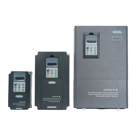
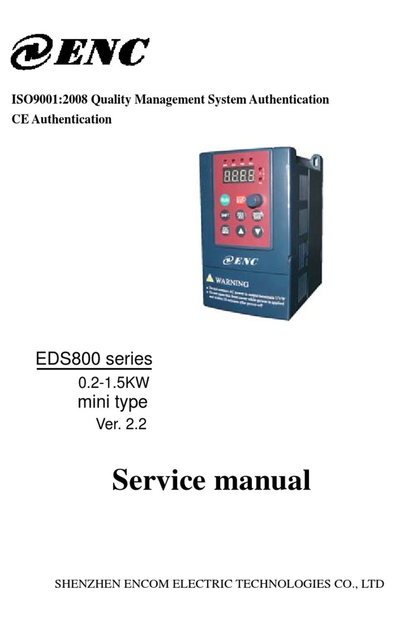
ENC EDS300 Series User manual

0.2-3.7KW
EDS300 Series
Ver.1.1
ISO9001:2015 Quality Management System Authentication
SHENZHEN ENCOM ELECTRIC TECHNOLOGIES CO., LTD
Users’ Manual

Print version: V1.1
Foreword
Encom EDS300 are designed and produced according to EN61800-5-1: 2007,
EN 61010-1: 2010, EN61800-3: 2004+A1: 2012 standards.
Thank you for purchasing EDS300 series mini universal inverter from
Shenzhen Encom Electric Technologies CO., LTD.
EDS300 series frequency converter adopts advanced control mode to realize
high torque, high precision and wide speed regulation drive, which can meet various
requirements of general frequency converter. EDS300 is the organic combination of
general customer demand and industry demands, to provide a practical PID
controller, a simple PLC, programmable input/output terminal control, remote
synchronization control, pulse frequency and other special frequency converter
control powerful functions. It is of great value to reduce the cost and improve the
reliability of the system by providing the customers of equipment manufacturing and
automation engineering with the integrated solution of high integration.
EDS300 use the space voltage vector PWM control and without sensor vector
control technology and electromagnetic compatibility overall design, to meet the
customer for the applicable place of large torque low noise, low electromagnetic
interference environmental requirements.
Assembling wiring, parameter setting, troubleshooting and daily maintenance
notice are available in this manual. To make sure that you can correctly assemble
and operate EDS300 series inverters to exert their excellent performance, please
read this user manual detailedly before you assemble the device and conserve the
manual appropriately before the end-user get them.
Please contact our office or dealer in all places at any moment if you have any
doubts or special demands when using these inverters, and you can also contact our
after service center in our headquarters directly. We will serve you with all our heart.
We reserve our right to notice you if we change contents of this manual.
ENC

Contets
Contents
1 Safety information and use notice points.............................................................. 1
1.1 Safety Precautions ............................................................................................ 1
1.2 Use Range......................................................................................................... 2
1.3 Use Notice Points ............................................................................................. 2
1.4 Scrap Notice Points .......................................................................................... 3
2 Type and specification of the inverter................................................................... 4
2.1 Incoming Inverter Inspect ................................................................................ 4
2.2 Type Explanation ............................................................................................. 4
2.3 Nameplate explanation ..................................................................................... 4
2.4 Series type explanation..................................................................................... 5
2.5 Appearance and parts name explanation.......................................................... 5
2.6 Outer size and gross weight ............................................................................. 6
2.7 Outer size of keypad and its fixing box (unit: mm) ......................................... 6
2.8 Product Technic Index And Spec..................................................................... 7
3 Installation and wiring............................................................................................ 9
3.1 Installation ambient .......................................................................................... 9
3.1.1 Demand for installation ambient............................................................. 9
3.1.2 Installation direction and space............................................................... 9
3.2 Parts disassembly and installation.................................................................. 10
3.2.1 Key board disassembly and installation................................................ 10
3.2.2 Plastic cover disassembly...................................................................... 10
3.3 Wiring notice points ....................................................................................... 10
3.4 Main loop terminal wiring.............................................................................. 11
3.4.1 Connection between inverter and fitting parts...................................... 11
3.4.2 Main loop terminal wiring .................................................................... 12
3.5 Basic running wiring diagram ........................................................................ 13
3.6 Control loop collocation and wiring .............................................................. 14
3.6.1 Location & function of terminal and jump-wire................................... 14
3.6.2 Explanation for control CPU board ...................................................... 14
3.6.3 Analog input output terminal wiring..................................................... 16
3.6.4 Communication terminal wiring ........................................................... 16
4 Function parameter schedule graph ................................................................... 18
4.1 Symbol description......................................................................................... 18
4.2 Function parameter schedule graph ............................................................... 18
5 Trouble Shooting ................................................................................................... 31
5.1 Failure and countermeasure ........................................................................... 31
5.2 Failure record lookup ..................................................................................... 34
5.3 Fault reset ....................................................................................................... 34
ENC

Contets
6 Maintenance........................................................................................................... 35
6.1 Routine maintenance ...................................................................................... 35
6.2 Inspection and replacement of damageable parts .......................................... 35
6.3 Repair guarantee............................................................................................. 36
6.4 Storage ............................................................................................................ 36
7 Modbus Communication Protocol....................................................................... 37
7.1 Summarization................................................................................................ 37
7.2 Networking mode for communication networking........................................ 37
7.3 Communication mode .................................................................................... 37
7.4 RTU communication Mode............................................................................ 38
7.5 Data communication address allocation......................................................... 39
7.6 Communication error processing ................................................................... 41
7.7 Data frame examples ...................................................................................... 41
7.8 CRC check mode............................................................................................ 43
Appendix A Serial port 485 communication protocol.......................................... 44
Appendix B Braking Resistance ............................................................................. 52
ENC

Safety information and use notice points
1
1 Safety information and use notice points
In order to ensure the safety of your personal and equipment, before using the
inverter please read this chapter of contents conscientiously.
1.1 Safety Precautions
There are three kinds of safe relevant warnings in this service manual, they are
as follows:
Symbol Symbol description
This symbol explains items that need to be paid attention to when being
operated.
This symbol is briefed on some useful information.
This symbol briefs on: If does not operate on request, may cause death,
severely injured or serious property loss.
!
Note
!
(1) Forbid to connect U, V, W output end to AC power supply, otherwise cause
the complete damage of the inverter.
(2) Don't make P- and P + short-circuited, otherwise cause the inverter to be
damaged.
(3) The inverter is forbidden to install on the flammables, otherwise have danger
of fire.
(4) Don't install it in the environment with explosive gas, otherwise have danger
of causing explosion.
(5) After connecting main loop, should carry on insulating treatment to bare
wiring end, otherwise have danger of getting an electric shock.
(6) If being connected to the power supply, don't operate the inverter with moist
handsotherwise have danger of getting an electric shock.
(7) The ground terminal of the inverter must be grounded well.
(8) Inverter being connected to power supply, please don't open cover and carry
onwiring, can connect the wire or check only after closing power for 10 minutes.
(9) Only qualified personnel may carry on wiring and forbid leaving over any
conductive thing in machine, otherwise have danger of getting an electric shock
or causing damage of the inverter.
(10) Inverter stored for over 2 years, should be stepped up gradually with voltage
regulator first while having the electricity, otherwise have danger of getting
electric shock and explosion.
!
ENC
This manual suits for next models
9
Table of contents
Other ENC Inverter manuals
Popular Inverter manuals by other brands

BARRON
BARRON EXITRONIX Tucson Micro Series installation instructions

Baumer
Baumer HUBNER TDP 0,2 Series Mounting and operating instructions

electroil
electroil ITTPD11W-RS-BC Operation and Maintenance Handbook

Silicon Solar
Silicon Solar TPS555-1230 instruction manual

Mission Critical
Mission Critical Xantrex Freedom SW-RVC owner's guide

HP
HP 3312A Operating and service manual


