MDS Power IPSi2400X User manual

INSTALLATION &
OPERATION MANUAL
IPSi2400X
STEEL MILL
INVERTER
T.T.514.369.4919 TF. 800.931.49
www.mdspower.com

2

SAVE THESE INSTRUCTIONS — This manual contains important safety and operating
instructions for the Inverter.
GENERAL PRECAUTIONS
1. Do not expose the Inverter to rain or snow.
2. Use of an attachment not recommended or sold by the Inverter manufacturer may result
in a risk of re, electric shock, or injury to persons.
3. Do not disassemble the Inverter; take it to a qualied serviceman when service or repair
is required. Incorrect reassembly may result in a risk of electric shock or re.
4. To reduce risk of electric shock, disconnect the Inverter from the input power before at-
tempting any maintenance or cleaning. Turning off controls will not reduce this risk.
5. Never place the Inverter directly above a battery; gases from the battery will corrode and
damage the Inverter.
6. Never allow battery acid to drip onto the Inverter.
HEAVY DEVICE - The IPSi2400 and IPSi3600 Inverters weigh more than 50 pounds and 70
pounds respectively. Please use appropriate safety measures when lifting or moving these
units.
MEDICAL EQUIPMENT NOTICE
This product is not recommmended the use of their products in life support applications
where failure or malfunction of this product can be reasonably expected to cause failure of
the life support device or to signicantly affect its safety or effectiveness. Additionally, iot
is not recommended for use with any products in direct patient care. Examples of devices
considered to be life support devices are neonatal oxygen analyzers, nerve stimulators
(whether used for anesthesia, pain relief, or other purposes), auto-transfusion devices,
blood pumps, debrillators, arrhythmia detectors and alarms, pacemakers, hemodialy-
sis systems, peritoneal dialysis systems, neonatal ventilator incubators, ventilators for
both adults and infants, anesthesia ventilators, and infusion pumps as well as any other
devices designated as “critical” by the U.S. FDA
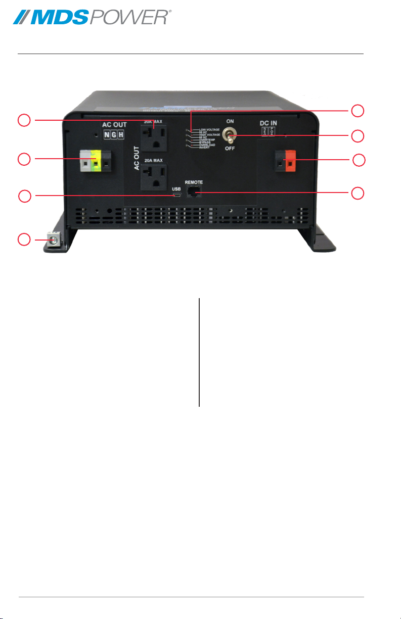
GROUNDING AND AC POWER CORD CONNECTION INSTRUCTIONS — Inverters
should be grounded to reduce risk of electric shock. This Inverter is equipped with a
chassis grounding stud, and electric receptacles capable of accepting an equipment-
grounding conductor and a grounding plug.
INVERTER
IMPORTANT SAFETY INSTRUCTIONS

TABLE OF CONTENTS
• Front Cover
• Product Warnings and Advisories
• Table of Contents
• Introduction
• Box Contents
• Main Parts
• Operation
• Installation
• Options
• Troubleshooting
• Specications
• Warranty
5

The box you have received should contain the following:
• One IPSi2405 High Voltage Inverter
• One MicroUSB to USB cable
• This User Guide
• One Warranty Card
If anything is missing or damaged please contact your dealer for a replacement.
Box Contents
5
Introduction
The IPSi1205/2405 series High Voltage Inverters are designed specically for powering on-
board computers and sensitive AC loads from high voltage (205-390 VDC) DC power sources.
The transformer-based design also allows us to provide double the rated power for a few
seconds which means that we can start up electric motors, shop vacuums, air conditioners and
other difcult AC loads.
This unit is controlled by a Digital Signal Processor for optimal control and operation. The
unit’s heavy-duty toroidal power transformer steps up the low AC voltage produced by the
MOSFET transistors to either 110 or 220VAC at 50 or 60 Hz, identical to a conventional
AC outlet. Additional output ltering eliminates noise that could potentially interfere with
sensitive communications equipment.
Designed for service in extreme environments, this unit is IPX1 splash resistant and IP4Y dust
resistant. This unit has also been designed to meet the MIL-STD810h standards for operating
temperature range and shock and vibration protection.
Built for maximum safety and reliability, the unit features current limiting, feedback protection,
short circuit protection, over temperature detection and shutdown and undervoltage and
overvoltage detection and shutdown (thresholds user-adjustable).

Main Parts
1
2
1. AC Output Connection 1: 2x
NEMA 5-20 AC receptacle 739W-
X2/20
2. AC Output Connection 2: 3x
Phoenix VDFK4 Terminal Block
connector (Black: Hot, Green:
Ground, Grey: Neutral)
3. USB Communications Port
4. Chassis Grounding Stud
5. Indicator LEDs
6. Power Switch
7. DC Input Connection: 2x Phoenix
VDFK4 Terminal Block connector
(Red: Positive, Black: Negative)
8. Remote Control Connection
Front Panel
4
6
5
7
8
3
76

Operation
This unit is designed for simple and intuitive operation. Before operating, the inverter must be
properly installed and connected. See Installation and AC/DC Connections for more information.
TO OPERATE THE INVERTER:
1. Move the Power Switch to ON to energize the circuitry.
2. The Invert LED and either the 50 Hz or 60 Hz LED will glow green indicating proper
operation and the presence of AC power at the outputs.
3. The inverter will automatically begin supplying the connected load with voltage and
current printed on its label.
TO END OPERATION:
1. Move the Power Switch to OFF to end operation.
2. Wait for all the LEDs to turn off.
3. The inverter can now be safely disconnected from the load and power source. It can then be
serviced or put into storage.
There are eight indicator LEDs on the inverter’s front panel which display it’s operating condition.
The table below details their meanings:
LEDs Meaning
LOW
VOLTAGE
• Blinks red when the input voltage nears the minimum limit for proper operation.
• Glows red when the input voltage is too low for proper operation. The Bypass
LED will also glow red and the Invert LED will turn off.
HIGH
VOLTAGE
• Blinks red when the input voltage nears the maximum limit for proper operation.
• Glows red when the input voltage is too high for proper operation. The Bypass
LED will also glow red and the Invert LED will turn off.
OVER TEMP • Blinks red when the unit’s internal temperature nears the safe limit. The
inverter will automatically derate its maximum power rating to try to
maintain a safe operating temperature.
• Glows red when the inverter is too hot to operate. The Bypass LED will
also glow red and the Invert LED will turn off.
OVER LOAD • Blinks red when the current being drawn reaches the unit’s continuous rating.
• Glows red when the current being drawn reaches the unit’s peak rating.
50 HZ • Glows green if the inverter’s output frequency is set to 50.00 Hz. This
setting can be changed using InverterWizard,
60 HZ • Glows green if the inverter’s output frequency is set to 60.00 Hz. This set-
ting can be changed using InverterWizard.
BYPASS • Glows green if the inverter is in Bypass mode and functioning as an Off-line
Uninterruptible Power Supply. For more information, see Off-line UPS.
• Glows red when the inverter is experiencing a malfunction.
INVERT • Glows green when the inverter operating normally.
7

8
MOUNTING
Mount the inverter on a horizontal surface in
a WELL VENTILATED and DRY area with at
least 1 inch (2.54 cm) of clearance all around
the unit.
CAUTION: THE UNIT MUST BE
MOUNTED ON A FLAT HORIZONTAL
SURFACE.
The heavy-duty toroidal power transformer
inside the inverter weighs 50+ pounds. Unless
the unit is mounted horizontally, it could break
free from its single mounting bolt under severe
vibration.
GROUNDING
The unit case is connected to AC Ground and AC Neutral in order to meet regulatory
requirements and reduce the possibility of it generating any radio frequency interference.
The unit case must be bonded appropriately to the grounding system of the vehicle or marine
vessel. On a vehicle, bond the case to the vehicle’s frame. On a marine vessel, bond the case
to the vessel’s hull. A grounding stud is provided on the front panel for this purpose.
To ensure proper grounding, check the connection with an ohmmeter. The case is isolated from
the DC input, so the DC power can be connected to a different ground from the AC output.
DISCONNECTING
If you need to disconnect the inverter for service or storage:
1. Move the power switch to OFF and disconnect the DC power source.
2. With power disconnected, move the power switch to ON.
3. Leave the switch in this position for one minute to discharge the storage capacitors.
4. Return the power switch to the OFF position. Disconnect the load(s).
5. The inverter is ready for service or storage.
Installation

9
DC Connections
BEFORE MAKING ANY CONNECTIONS, MAKE THE POWER SWITCH IS OFF.BEFORE MAKING ANY CONNECTIONS, MAKE THE POWER SWITCH IS OFF.
INPUT CONNECTION
This unit is equipped two Phoenix VDFK-4 terminal block connector s to serve as an DC Input
connection. Before making any connections, prepare a circuit-breaker protected power source,
making sure the breaker is OFF.
The wiring for this connection can be found on the unit’s front panel label. It is also detailed
below:
TIP: For maximum safety, make sure end of the wire insulation butts is ush with the terminal
so no non-insulated wire if visible. Trim the length of non-insulated wire if necessary.
RECOMMENDATION: USE THE LARGEST GAUGE (AWG 1/0) RECOMMENDED) AND
SHORTEST LENGTH OF WELDING WIRE POSSIBLE.
The biggest effect on Inverter performance and EMI is the length and gauge of the DC Input
connections.
CAUTION: DO NOT REVERSE CONNECT THE INPUT WIRES.
This will cause trigger the unit’s reverse polarity protection blowing the interal fuses. The unit
will be inoperable until these fuses are replaced.
Color Polarity
Red DC Positive
Black DC Negative

1110
Color Line
Gray AC Neutral
Green AC Ground
Black AC Hot/Live
AC Connections
BEFORE MAKING ANY CONNECTIONS, MAKE THE POWER SWITCH IS OFF.BEFORE MAKING ANY CONNECTIONS, MAKE THE POWER SWITCH IS OFF.
OUTPUT CONNECTIONS
This unit is equipped with two AC Output connections.
• One standard circuit breaker protected 20 Amp NEMA 5-15 AC receptacle .
• Three 30 amp, 250V rated CSA/UL approved Phoenix VDFK-4 terminal block connectors.
The wiring for this connection can be found on the unit’s front panel label. It is also
detailed below:
CAUTION: THE TERMINAL BLOCK IS NOT CIRCUIT BREAKER-PROTECTED.
Each device wired to this connection must have its own breaker. Ensure that the total average
load of all the devices does not exceed the continuous current rating of the unit.
CAUTION: DO NOT APPLY AC VOLTAGE TO THE OUTPUT
This will cause serious damage to the Inverter and will not be covered by the warranty.

Troubleshooting
This unit features eight LED indicators and an alarm buzzer to help diagnose any malfunctions
during operation. In the event of malfunction, the alarm buzzer will sound prior to the inverter
shutting down. You should immediately check which LEDs are glowing to determine the cause
of the malfunction.
TIP: FOR QUICK REFERENCE, IF THE UNIT IS EXPERIENCING A MALFUNCTION: THE INVERT
LED WILL BE OFF AND THE BYPASS LED WILL BE GLOWING RED.
LED / Issue Meaning
LOW VOLTAGE LED is ON The input voltage is too low for normal operation.
Fix: Check that the power source is appropriately rated for use with the
inverter. If using InverterWizard, check the Low Voltage Alarm thresh-
olds are properly set for the battery voltage you are using to power the
inverter, for example: 21V for a 24V battery and 28V for a 32V battery.
If the above are all in working order, the cause is likely an internal
component failure and the unit must be returned for repair.
HIGH VOLTAGE LED is ON The input voltage is too high for normal operation.
Fix: Check that the power source is appropriately rated for use with the
inverter. The inverter can be damaged if the input voltage exceeds the
rating indicated on the label. Over-voltage damage is not covered under
warranty.
If the above are checked and in working order, the cause is likely an
internal component failure and the unit must be returned for repair.
OVER TEMP LED is ON The unit’s internal temperature is too hot for normal operation.
Fix: Check that the unit’s cooling fans are functioning. If the fans are NOT
running, the unit must be returned for repair. If the fans are running,
you may need to remount the inverter for improved ventilation.
The inverter will automatically derate its maximum power rating to
maintain a safe operating temperature. If the internal temperature
exceeds the safe maximum, the unit will shut off its outputs. When the
temperature drops to safe operating range, the inverter will automati-
cally ecover.
OVER LOAD LED is ON The load is drawing too much current from the inverter.
Fix: The load has been drawing the peak current from the inverter for
longer than its intended duty cycle. Reduce the load on the inverter by
disconnecting some devices from the output.
1110

1312
Remote Port (Optional)
This port is intended to be used with a Digital Remote Control add-on, but it can also be used
for as a Remote On/Off switch, Isolated RS232 Communications terminal and Dry Contact
Output Fail indicator. The remote port uses a standard RJ45 style connector with proprietary
connections. Do not connect this port to a computer. The wire colors described below
correspond to colors found in any standard T-568B network cable.
CAUTION: DO NOT CONNECT THIS PORT TO A COMPUTER
This will cause serious damage to the Inverter and the computer. This will not be covered
under warranty.
Pin Number Wire Color Function
1 White/Orange Stripe Remote ON/OFF
2 Orange Digital Ground
3 White/Green Stripe +12V Out
4 Blue RX RS232
5 White/Blue Stripe TX RS232
6 Green Gnd RS232
7 White/Brown Dry Contact Relay
8 Brown Dry Contact Relay
Remote On/Off
Pins 1 (White/Orange) and 2 (Orange) are used to turn the Inverter ON or OFF. Connect them
together through a switch or relay to turn the Inverter OFF and disconnect them to turn the
Inverter ON. The main power switch must be ON for this connection to function.
Isolated RS232 Communications
Pins 4 (Blue), 5 (White/Blue) and 6 (Green) are an isolated RS232 port that can be used for
communication to/from the Inverter. Information on the standard data structure or custom
programming is available from the factory. Pin 4 is RX, Pin 5 is TX and Pin 6 is Return.
Dry Contact Output Fail Relay
Pins 7 and 8 (White/Brown and Brown) connect to the contacts of an Output Fail relay
controlled by the processor. The contacts will be CLOSED if the Inverter is operating normally
and OPEN if the Inverter has failed.

1312
THis page has been intentionally left blank.

14
Specications
Input
Input Voltage Range 205 -390 VDC
Maximum Input Current < 20A
Undervoltage Input Threshold < 180 VDC
Overvoltage Input Threshold > 390 VDC
Reverse Polarity Protection Yes
Output
Voltage 110 ± 2 VAC 220 ± 4 VAC
Output Amps (cont) 22.0 A (Cont.) / 28.0 A (Max.) 10.0 A ( Cont.) / 12.0 A (Max.)
Output Frequency 50.00 or 60.00 ± <1 Hz
Duty Cycle Capable of 2x Maximum Output Power for 10 seconds
Maximum Output Power 1205 series: 1200W
2405 series: 2400W
Output Connection
AC OUT 1: 2x NEMA 5-20 AC receptacle 739W-X2/20
AC OUT 2: 3x Phoenix VDFK-4 Terminal Block (Black: Hot, Green: Ground, Grey: Neutral)
DC IN: 2x Phoenix VDFK-4 Terminal Block (Red: Positive and Black: Negative)
* Specications subjects to change without notice.
General
Efciency > 80% @ Maximum Output
Temp. Range -40°C to +55°C @ Maximum Output
Emissions Designed to meet FCC Part 15 Class A
Shock and Vibration Designed to meet MIL-STD810H
ROHS3 Compliant Yes
Connectors
AC OUT 1- Universal AC Receptable S.203013
AC OUT 2- Phoenix VDFK-4 Terminal Block (Black: Hot, Green: Ground and Grey:
Neutral)
DC IN - Phoenix VDFK-4 Terminal Block (Red: Positive and Black: Negative)
Length 18.68 in /47.45 cm
Width 11.75 in / 29.85 cm (including mounting anges)
Height 5.60 in / 14.22cm
Clearance 1.00 in / 2.54 cm (all around)
Material Marine grade aluminum
Finish Black powder epoxy/Black anodized
Fastenings 18-8 Stainless steel
Weight 52.5 lb / 24.0 kg (Approximate)

Limited Warranty
1. The equipment manufactured by Analytic Systems Ware (1993) Ltd. (the “Warrantor”) is warranted to be free
from defects in workmanship and materials under normal use and service.
2. This warranty is in effect for:
a. 5 Years from date of purchase by the end user for standard products offered in our catalog.
b. 2 Years from date of manufacture for non-standard or OEM products
c. 1 Year from date of manufacture for encapsulated products.
3. Analytic Systems will determine eligibility for warranty from the date of purchase shown on the warranty card
when returned within 30 days, or
a. The date of shipment by Analytic Systems, or
b. The date of manufacture coded in the serial number, or
c. From a copy of the original purchase receipt showing the date of purchase by the user.
4. In case any part of the equipment proves to be defective, the Purchaser should do the following:
a. Prepare a written statement of the nature of the defect to the best of the Purchasers knowledge, and
include the date of purchase, the place of purchase, and the Purchasers name, address and telephone
number.
b. Call Analytic Systems at 800-668-3884 or 604-946-9981 and request a return material authorization
number (RMA).
c. Return the defective part or unit along with the statement at the Purchasers expense to the Warrantor;
Analytic Systems Ware (1993) Ltd., 8128 River Way, Delta, B.C., V4G 1K5, Canada.
5. If upon the Warrantor’s examination the defect proves to be the result of defective material or workmanship,
the equipment will be repaired or replaced at the Warrantor’s option without charge, and returned to the
Purchaser at the Warrantor’s expense by the most economical means. Requests for a different method of return
or special handling will incur additional charges and are the responsibility of the Purchaser.
6. Analytic Systems reserves the right to void the warranty if:
a. Labels, identication marks or serial numbers are removed or altered in any way.
b. Our invoice is unpaid.
c. The defect is the result of misuse, neglect, improper installation, environmental conditions, non-autho-
rized repair, alteration or accident.
7. No refund of the purchase price will be granted to the Purchaser, unless the Warrantor is unable to remedy the
defect after having a reasonable number of opportunities to do so.
8. Only the Warrantor shall perform warranty service. Any attempt to remedy the defect by anyone else shall
render this warranty void.
9. There shall be no warranty for defects or damages caused by faulty installation or hook-up, abuse or misuse of
the equipment including exposure to excessive heat, salt or fresh water spray, or water immersion except for
equipment specically stated to be waterproof.
10. No other express warranty is hereby given and there are no warranties that extend beyond those described
herein. This warranty is expressly in lieu of any other expressed or implied warranties, including any implied
warranty of merchantability, tness for the ordinary purposes for which such goods are used, or tness for a
particular purpose, or any other obligations on the part of the Warrantor or its employees and representatives.
11. There shall be no responsibility or liability whatsoever on the part of the Warrantor or its employees and rep-
resentatives for injury to any person or persons, or damage to property, or loss of income or prot, or any other
consequential or resulting damage which may be claimed to have been incurred through the use or sale of the
equipment, including any possible failure of malfunction of the equipment, or part thereof.
12. The Warrantor assumes no liability for incidental or consequential damages of any kind

800-931-4919
514-369-1919
order@mdspower.com
www.mdspower.com
DESIGNED AND BUILT IN CANADA
Table of contents
Other MDS Power Inverter manuals