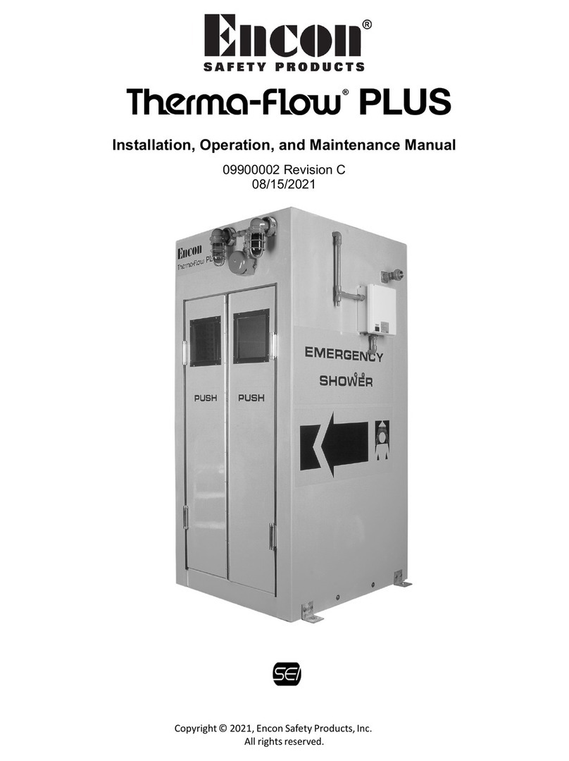
ENCON SAF-T-FLO STF30 Series User manual

ENCON®SAFETY PRODUCTS
SAF-T-FLO®
EMERGENCY SHOWER & EYEWASH
WATER TEMPERING SYSTEM
INSTALLATION, OPERATION
AND MAINTENANCE MANUAL
MODEL:
STF30 & STF60 SERIES
09900003A Rev. F
Copyright Encon®Safety Products 2004
June 10, 2004
1st Printing
Patent # 6,270,014 B1

Doc. No.: 09900003A Rev. F Page 1 of 26
Issue Date: 07-19-11
SAF-T-FLO®
PATENT# 6,270,014 B1
PRODUCTION DESCRIPTION
The SAF-T-FLO®is a water tempering system designed to deliver tepid (Encon’s desired output temp is
78F - 93F [25.5C - 33.8C ]) water to emergency eyewash and shower equipment (ESEW) when
supplied with adequate amounts of hot and cold water (see OPERATIONAL SPECIFICATIONS below
for requirements). Through an electro-mechanical series of controls, the SAF-T-FLO® will blend from 3
to 30 gpm (STF30 series) or 8 to 60 gpm (STF60 series) of water to a tepid temperature, while
providing the necessary safeguards to help ensure end user safety. In the event of an electrical power
failure, mechanical component failure or flow restriction, the SAF-T-FLO®“fail-safe” controls work to
eliminate hot water use and provide a cold supply water flow only (bypass mode). The SAF-T-FLO®
can be installed to serve a single ESEW station or plumbed to serve multiple ESEW stations.
OPERATIONAL SPECIFICATIONS
Electrical Requirement:
No heater: 120 Volt AC, 0.16 Amp
With heater: 120 Volt AC, 1.0 Amp
No heater: 240 Volt AC, 0.16 Amp
Alarm relay capacity: 3 Amps
Size:STF30 Series: Without case: 32 ¾” long X 18” wide X 9 ¾”” deep
With case: 37 ¾” long x 22”wide x 15 7/8” deep
STF60 Series: Without case: 42 1/8”long X 18” wide X 11” deep
With case: 42 1/8”long x 22”wide x 15 7/8” deep
Weight:
STF30 Series: Without case: Approx. 49 pounds
With case: Approx. 79 pounds
STF60 Series: Without case: Approx. 75 pounds
With case: Approx. 105 pounds
Maximum design water flow rate: STF30 Series: 30 gpm
STF60 Series: 60 gpm
Pressure drops as follows:
3.5 gpm: 5 psig
8.0 gpm: 8 psig
20 gpm: 15 psig
30 gpm: 20 psig
Recommend water quality: potable water
Inlet / Outlet connections: STF30 Series: 1” Coupling (water), ¾” Coupling (electrical)
STF60 Series: 1 ½” Coupling (water), ¾” Coupling (electrical)
Water temperature requirements:
Cold: 75F (23.9C) max 33F (0.56C) minimum
Hot: 160F (71C) max 90F (32C) minimum
Outlet temperature: 80to 90F (26.7to 32C) design temperature
85F (29.4) target temperature

Doc. No.: 09900003A Rev. F Page 2 of 26
Issue Date: 07-19-11
I. OPERATION
During static (non-flowing) conditions, an independent LED will indicate the following: POWER ON
indicator will be lit and the BLENDING and FLOW lights will be off. For optimum performance the
hot water inlet temperature should be between 90and 160°F (32.2and 71.1C) and the cold
water inlet temperature should be between 33and 75°F (0.56and 23.9C). During flow
conditions, the Water Outlet Temperature gauge should be between 80and 90°F (26.7and
32.2C) and LED will indicate the following: POWER ON, BLENDING and FLOW indicators will be
lit.
If an upset situation occurs upon activation of flow and the thermostat detects blended water above
92F (33.3C),the 2-SOL solenoid valve closes to shut off the tepid water flow and the bypass
solenoid (1-SOL) opens to bypass the blending valve to provide a cold water flow, the BLENDING
indicator light is off, and the FLOW indicator light is on. Upon return to proper water temperature
(lower than 92F [33.3C]), the bypass solenoid closes, the tepid water solenoid valve opens, and
the BLENDING indicator light is lit.
II. INSPECTION AND INSTALLATION
A. DIRECTIONS
1. Remove Saf-T-Flofrom shipping carton/pallet.
2. Inspect unit for external damage. If damages are discovered, notify your transport carrier
and proceed with claim with the transport carrier.
3. Mount Saf-T-Floto wall, structural steel or ”I” beam using the mounting bolt holes located
in the piping support steel within the enclosure, if there is one. The Saf-T-Flocan be
positioned upright horizontally with the inlet pipes entering the top of the unit or vertically
with the inlet pipes entering either the right or left of the unit. The unit cannot lie flat in
operation or for testing purposes.
NOTE: Mounting hardware not included.
4. Prior to connecting the hot and cold water supply lines to the Saf-T-Floinlet union
connections, flush the hot and cold water supply lines assuring any foreign particulate is
removed from supply lines. It is recommended that 100 mesh strainers and, if necessary,
dielectric unions can be installed at the inlet connections.
5. Connect the blended water outlet to the shower supply piping.
CAUTION CAUTION CAUTION
ADEQUATE WALL SUPPORT IS RECOMMENDED.
THE UNIT C
ANNOT LIE FLAT IN OPERATION OR FOR TESTING PURPOSES.
CAUTION CAUTION CAUTION
ENSURE CORRECT CONNECTIONS OF HOT AND COLD WATER SUPPLY LINES.
REVERSE CONNECTIONS WILL RESULT IN OVER TEMERATURE WATER DISCHARGE
FROM THE UNIT.

Doc. No.: 09900003A Rev. F Page 3 of 26
Issue Date: 07-19-11
6. Connect electrical supply, 120/240 volt (check model for proper voltage connection), to
terminals 1TB1 and 1TB2 in the junction box. Refer to Diagram 4 in Section VII.
7. If applicable, connect remote alarm signal or electrical supply to 1-CR contacts 10 and 2
(N.C.) 2TB or 10 and 6 (N.O.) 2TB enabling operational alarm under main electrical power
failure conditions. Contact rating is 3 amps at 120 volts or 3 amps at 240 volts.
B. START-UP
1. Alert control room or appropriate personnel of potential alarm, if applicable.
2. Open cold water supply valve.
3. Open hot water supply valve.
4. Energize electrical circuit.
5. Actuate Emergency Shower Eyewash equipment down stream of the Saf-T-Flo.
6. Observe the Saf-T-Floperformance by comparing to the description in Section I -
OPERATION.
NOTE: If Saf-T-Flodoes not function per the description in Section I - OPERATION, consult
Section V - TROUBLESHOOTING.
III. TESTING AND INSPECTION
A. Test of the Saf-T-Flois limited to activating a shower unit down stream of the Saf-T-Flo, and
observing the Water Outlet Temperature gauge and indicator lights. During flow conditions, the
Water Outlet Temperature gauge should be between 80and 90°F (26.7and 32.2C) and LED
will indicate the following: POWER ON, BLENDING and FLOW indicators will be lit. Should the
BLENDING or FLOW indicator light remain off following activation of flow, consult Section V -
TROUBLESHOOTING.
B. ALARM TEST (if applicable)
Upon flow activation, the flow switch alarm can be checked locally by opening the junction box
cover and checking continuity across the I-CR contacts, 2TB1 and 2TB2 (N.C.) or 2TB1 and
2TB3 (N.O.). Refer to Diagram 4 in Section VII.
CAUTION CAUTION CAUTION
TO AVOID ELECTRICAL SHOCK, DISCONNECT POWER BEFORE PROCEEDING! DE-
ENERGIZE AT CIRCUIT BREAKER.
CARE MUST BE TAKEN WHEN OPENING JUNCTION BOX COVER TO PROTECT THE
INDICATING LIGHT WIRING INSIDE THE BOX.
GROUNDING LUG HAS BEEN PROVIDED TO BASE PLATE OF JUNCTION BOX.
CUSTOMER TO PROVIDE ADEQUATE GROUND AT MAIN POWER SUPPLY FEED.
CAUTION CAUTION CAUTION
CARE MUST BE TAKEN WHEN OPENING JUNCTION BOX COVER WHILE ELECTRICAL
POWER IS CONNECTED AND ON.
PROTECTION OF THE INDICATING LIGHT WIRING INSIDE THE BOX IS ALSO
RECOMMENDED.

Doc. No.: 09900003A Rev. F Page 4 of 26
Issue Date: 07-19-11
IV. MAINTENANCE
Maintenance is typically limited to testing the emergency shower equipment down stream of the
Saf-T-Flo. However, should problems occur on the Saf-T-Flo, the use of Section V -
TROUBLESHOOTING can help isolate those components requiring repair or replacement. An
adjustable locking wrench applied to unions is the recommended hand tool for repairs and
maintenance, unless noted otherwise.
A. FLOW SWITCH - 1-FLS
Flow switch 1-FLS is used as a normally closed switch; as such, electrical continuity testing will
determine the proper operation of the flow switch. Refer to Diagram 4 in Section VII.
1. Removal of Flow Switch Bonnet Assembly – 1-FLS:
a) Carefully open junction box cover while protecting the indicating light wiring. The
indicating light leads are wired to the terminal strip and must remain properly connected
to facilitate rapid maintenance.
b) With power off, disconnect 1-FLS power leads from 1TB1 and 1TB3. Tie a piece of
pulling line to the wires to assist in re-assembly.
c) The flow switch is a pressure component, ensure all water lines are drained.
d) Separate conduit union at the electrical conduit run to the flow switch.
e) With the conduit union separated, loosen the 1-FLS bonnet nut using an adjustable
wrench. Remove the bonnet ring. Rotate bonnet assembly counterclockwise, clearing
the conduit and remove the bonnet assembly from flow switch body. Bonnet assembly
is shown in Figure A below.
f) You can now access the shuttle
assembly for testing and/or cleaning.
2. Electrical Testing of Flow Switch 1-FLS:
a) With the flow switch bonnet discon-
nected and removed from the Saf-T-
Flo, perform an electrical continuity
test using the red and black leads
(normally closed) for 1-FLS.
CAUTION CAUTION CAUTION
PRIOR TO ATTEMPTING MAINTENANCE:
TO AVOID ELECTRICAL SHOCK, DE-ENERGIZE SAF-T-FLOAT MAIN ELECTRICAL
POWER SUPPLY
DRAIN ALL WATER LINES.
CARE MUST BE TAKEN WHEN OPENING JUNCTION BOX COVER TO PROTECT THE
INDICATING LIGHT WIRING INSIDE THE BOX.
USE PIPE SEALANT SPARINGLY.

Doc. No.: 09900003A Rev. F Page 5 of 26
Issue Date: 07-19-11
b) 1-FLS will show electrical continuity or a closed circuit under no flow (N.C.) conditions.
Should the test show otherwise, operate the switch through a cycle (lift and drop shuttle,
test electrical continuity readings).
c) If the circuit remains closed throughout the cycling of the drop shuttle, clean all
particulate from the shuttle assembly and magnet. Remove Retainer Ring “A” for
complete shuttle disassembly. Remove Retainer Ring “B” to disassemble disc only.
d) Retest electrical continuity. If electrical continuity cannot be broken, switch contacts
have failed, and flow switch bonnet assembly will require replacement. See Section VI -
REPLACEMENT PARTS.
3. Replacement of 1-FLS:
Replacement procedure is the reverse order of disassembly.
4. Rewire and connect 1-FLS power leads to 1TB1 and 1TB3 for normal operation.
B. 3-WAY MIXING VALVE – 1-TCV
The 3-way mixing valve 1-TCV is a self-contained internal temperature sensing thermostatic
control device. The valve has a factory pre-set (fixed) set point and is non-adjustable. In
operation, the valve plug modulates, proportioning the hot and cold water, allowing the
temperature control element to adjust to it’s designed set point (80to 90°F [26.7to 32.2C]) .
Maintenance of the 1-TCV is limited to replacement of the temperature control element and
seals when variation in the controlled temperature is noticed. Seals should be replaced when
replacing element.
1. To remove the temperature control element 1-TCV, separate the pipe unions. Remove the
four (4) valve body bolts from 1-TCV exposing the temperature control element. Remove
the element and perform the element functionality test, refer to Figure B, page 6.
2. Element Functionality Test –
a) Element Test Hot Port Open - Immerse the sensing element in ice water, observing the
valve plug travel. The hot water flow port should open and the cold water flow port
should close.
CAUTION CAUTION CAUTION
PRIOR TO ATTEMPTING MAINTENANCE:
TO AVOID ELECTRICAL SHOCK, DE-ENERGIZE SAF-T-FLOAT MAIN ELECTRICAL
POWER SUPPLY
DRAIN ALL WATER LINES.
MIXING VALVE SHOULD BE ALLOWED TO COOL, IF HOT.
USE PIPE SEALANT SPARINGLY.

Doc. No.: 09900003A Rev. F Page 6 of 26
Issue Date: 07-19-11
b) Element Test Cold Port Open - Immerse the
sensing element in hot water (105F /40.6C)
to 110F/43.3C maximum) observing the
valve plug travel. The cold water flow port
should open and the hot water flow port
should close.
NOTE: The port control sleeve effects both
ports simultaneously. You will notice
when the hot water flow port is fully
open; the cold water flow port is fully
closed and vice-versa. If the
temperature control element does
not pass the functionality test,
replace the element. Repair kit
consisting of an element and seals is
available. See Section VI -
REPLACEMENT PARTS.
3. Installation of 3-Way Mixing Valve – 1-TCV Element:
a) Refer to Diagrams 2 and 3in Section VII for proper arrangement prior to installation.
b) The temperature control valve has two seals. Place valve element with the o-ring
installed into the inlet port section of the valve body assembly. Place the other lubricated
flat rubber gasket firmly on the body recess to ensure a proper seal.
c) Replace the outlet port valve body section and tighten the four (4) valve body bolts.
d) Reconnect the pipe union to complete installation.
C. SYSTEM THERMOSTAT – 1-TAS
The system thermostat 1-TAS is a non-adjustable (fixed set point) thermostat. In operation, its
function is to sense the outlet water temperature and control the solenoid valves (closed 1-SOL
and open 2-SOL). As a sealed component, maintenance is limited to re-placement. Refer to
Diagrams 2, 3 and 4in Section VII for reference.
CAUTION CAUTION CAUTION
PRIOR TO ATTEMPTING MAINTENANCE:
TO AVOID ELECTRICAL SHOCK, DE-ENERGIZE SAF-T-FLOAT MAIN ELECTRICAL
POWER SUPPLY AND DRAIN ALL WATER LINES.
CARE MUST BE TAKEN WHEN OPENING JUNCTION BOX COVER TO PROTECT THE
INDICATING LIGHT WIRING INSIDE THE BOX.
USE PIPE SEALANT SPARINGLY.
CAUTION CAUTION CAUTION
WEAR PROTECTIVE EQUIPMENT DURING HOT WATER TEST.

Doc. No.: 09900003A Rev. F Page 7 of 26
Issue Date: 07-19-11
1. Carefully open junction box cover while protecting the indicating light wiring. The indicating
light leads are wired to the terminal strip and must remain properly connected to facilitate
rapid maintenance.
2. With power off, disconnect 1-TAS power leads to 1TB4 and 1TB5. Tie a piece of pulling line
to the wires to assist in re-assembly.
3. Loosen the conduit union below the elbow and separate the conduit union at the junction
box. This will free 1-TAS conduit assembly from the unit.
4. Apply wrench to 1-TAS hex flats and remove 1-TAS from conduit assembly by turning
counterclockwise.
a) If testing is desired, an electrical continuity test can be performed by immersing 1-TAS in
cold water (75°F/23.9C). Electrical continuity meter should indicate contacts closed.
b) Immerse 1-TAS in hot water (95°F/35C); continuity should show open contacts.
5. If the above test procedure does not indicate satisfactory temperature operation, replace
thermostat 1-TAS. See Section VI - REPLACEMENT PARTS.
6. Replacement procedure is the reverse order of disassembly.
7. Rewire and connect 1-TAS power leads to 1TB4 and 1TB5 for normal operation.
D. THERMOMETER – 1-TI
The bimetal thermometer provides a visual temperature reading of the outlet water.
Maintenance is limited to periodic cleaning and periodic calibration of the instrument as
determined by the user. For 1-TI removal and installation procedures, see No. 3 below.
1. Cleaning:
a) Keep dial lens clean for proper viewing. Clean using commercial window cleaner.
b) Periodic cleaning of residue from the stem may be required to ensure thermometer
sensitivity.
2. Calibration:
a) Periodic calibration should be as determined by the user.
b) Carefully remove 1-TI and immerse stem into a temperature-calibrated medium.
Immerse entire stem or 4” minimum.
CAUTION CAUTION CAUTION
PRIOR TO ATTEMPTING MAINTENANCE:
TO AVOID ELECTRICAL SHOCK, DE-ENERGIZE SAF-T-FLOAT MAIN ELECTRICAL
POWER SUPPLY
DRAIN ALL WATER LINES.
CARE MUST BE TAKEN WHEN OPENING JUNCTION BOX COVER TO PROTECT THE
INDICATING LIGHT WIRING INSIDE THE BOX.
USE OF PIPE TAPE IS NOT RECOMMENDED, USE PIPE SEALANT SPARINGLY.

Doc. No.: 09900003A Rev. F Page 8 of 26
Issue Date: 07-19-11
c) Use a small open-end wrench or flat head screwdriver to turn the calibration screw. Turn
the calibration screw to adjust the thermometer pointer to the correct tempera-ture, if
necessary.
d) Reinstall 1-TI to unit. Follow installation procedures below.
3. 1-TI removal and installation procedures:
a) To remove, apply an open-end wrench of the appropriate size to the 1-TI hex screw and
remove by turning counterclockwise. Care must be taken to prevent damage to dial lens.
b) To reinstall, apply appropriate thread sealant on the hex screw and place 1-TI stem into
the thermowell. Carefully tighten the hex screw until a non-leaking fit is achieved and the
head is facing the desired position.
E. SOLENOID VALVES - 1-SOL and 2-SOL
The Saf-T-Flocontains two (2) solenoid valves: 1-SOL and 2-SOL. 1-SOL (a normally open
valve) is located in the bypass line adjacent to the cold water connection of the blending valve.
It operates as the bypass valve under over-temperature conditions. Prior to flow actuation, this
valve stays open allowing cold water to bypass the mixing valve 1-TCV. 2-SOL (a normally
closed valve) is located in the blended water outlet line. It is used to shut off the water flow if
high temperature is detected by thermostat 1-TAS. These two valves are wired in parallel and
are controlled by a flow switch 1-FLS and thermostat 1-TAS. 1-SOL and 2-SOL are used to
control and direct water flow in order to provide redundant safe guards against hot water
leaving the blending system. The valves also ensure there is water flow available to the
emergency shower stations at all times. Refer to Diagrams 1 through 4, Section VII.
Solenoid valve inspection is limited to checking proper operation and valve water leakage.
1. Terminal connections to the solenoid valves should be inspected periodically to ensure they
are tight and free of oxide build-up and dust.
2. Depending on service conditions and filtration utilized, it may be required to periodically
clean and/or replace worn components. Valve body need not be removed from the lines.
Valve rebuild kits are available. See Section VI - REPLACEMENT PARTS and Diagrams
5 and 6, Section VII.
CAUTION CAUTION CAUTION
PRIOR TO ATTEMPTING MAINTENANCE:
TO AVOID ELECTRICAL SHOCK, DE-ENERGIZE SAF-T-FLOAT MAIN ELECTRICAL
POWER SUPPLY
DRAIN ALL WATER LINES.
CARE MUST BE TAKEN WHEN OPENING JUNCTION BOX COVER TO PROTECT THE
INDICATING LIGHT WIRING INSIDE THE BOX.
USE PIPE SEALANT SPARINGLY.

Doc. No.: 09900003A Rev. F Page 9 of 26
Issue Date: 07-19-11
1-SOL Instructions for Inspection, Cleaning and/or Replacing Parts:
NOTE: For Electrical Schematic, refer to Diagram 4 in Section VII.
a) Verify 1-SOL solenoid is functioning.
1) Carefully open junction box cover while protecting the indicating light wiring. The
indicating light leads are wired to the terminal strip and must remain properly
connected to facilitate rapid maintenance.
2) In the junction box, disconnect 1-SOL leads from terminal 1TB5 (#6R) and connect
to TB1. When Saf-T-Flois electrically re-energized the valve (1-SOL) should now
be held CLOSED.
3) Close junction box cover. Place hand on solenoid valve body (1-SOL) when Saf-T-
Flois re-energized. Solenoid is functioning when momentary internal movement
in valve body is detected by hand.
4) De-energize Saf-T-Floand return unit to pre-test condition.
NOTE: Never replace a shorted solenoid until the cause has been determined. (i.e.,
plugged or worn plunger seal, no voltage, over voltage, etc). Consult
Section V - TROUBLESHOOTING.
b) Removal instructions for 1-SOL solenoid:
1) With power off, disconnect 1-SOL power leads from 1TB5 (#6R) and 1TB2 (#2W3).
Tie a piece of pulling line to the wires to assist in re-assembly.
2) Separate the conduit union as required to free 1-SOL from the junction box.
CAUTION CAUTION CAUTION
PRIOR TO ATTEMPTING MAINTENANCE:
TO AVOID ELECTRICAL SHOCK, DE-ENERGIZE SAF-T-FLOAT MAIN ELECTRICAL
POWER SUPPLY.
CARE MUST BE TAKEN WHEN OPENING JUNCTION BOX COVER TO PROTECT THE
INDICATING LIGHT WIRING INSIDE THE BOX.
CAUTION CAUTION CAUTION
PRIOR TO ATTEMPTING MAINTENANCE:
TO AVOID ELECTRICAL SHOCK, DE-ENERGIZE SAF-T-FLOAT MAIN ELECTRICAL
POWER SUPPLY
AND DRAIN ALL WATER LINES.
CARE MUST BE TAKEN WHEN OPENING JUNCTION BOX COVER TO PROTECT THE
INDICATING LIGHT WIRING INSIDE THE BOX.
USE PIPE SEALANT SPARINGLY.

Doc. No.: 09900003A Rev. F Page 10 of 26
Issue Date: 07-19-11
3) Remove the nut and washer from the solenoid. This will allow you to separate the
solenoid switch from the solenoid valve body.
4) Remove solenoid switch and leads from the electrical conduit assembly by turning
the solenoid counterclockwise, clearing the conduit assembly.
5) Inspect solenoid for cracks in the housing.
c) Inspect 1-SOL valve body.
1) Disassembly instructions for valve body: (For explosion view of parts, refer to
Diagram 5 in Section VII).
NOTE: Care should be taken to never remove the sleeve by clamping onto the
sleeve tube, as this may cause the tube to dent or bend. Do not use a pipe
wrench. Use a Skinner U99-011 wrench nut (included in the Valve Rebuild
Kit) directly onto the sleeve flange.
1.1) To unscrew the sleeve assembly, mate the wrench nut to the sleeve flange and
turn the wrench nut. The snubber, plunger, wave washer, stop, seal retainer,
plunger return spring and flange seal may now be removed.
1.2) Unscrew cover screws. Lift cover from valve body. The diaphragm return
spring, diaphragm assembly and O-ring can now be removed.
NOTE: If the cover cannot be easily lifted off the valve body, laterally tap the
cover or gently pry the cover from the body with a screwdriver. Care
should be taken not to damage the diaphragm, cover or body.
1.3) To disassemble the diaphragm assembly, remove the lock nut, seal,
diaphragm support plate, O-ring and screw.
2) Clean components using appropriate cleaning fluid (mild soap and water).
3) Examine these components for damage or wear and replace as needed. Check
seals for swelling, cracking or general deterioration. When the plunger lifts, it
normally makes contact with the sides and the sleeve stop. As a result, the top of
the plunger and the inside of the sleeve may show wear as well. The spring should
be inspected for worn or broken coils.
4) If replacement of internal part(s) is required, a valve rebuild kit should be used.
Parts included in each rebuild kit are marked with an asterisk (*) shown in Diagram
5in Section VII.
5) Inspect orifices in the cover and valve body for nicks and debris. If dirt or mineral
build-up is present, clean with appropriate cleaning fluid. Replace with new 1-SOL if
damage is evident. See Section VI - REPLACEMENT PARTS.
CAUTION CAUTION CAUTION
DO NOT EXPOSE PLASTIC OR ELASTROMERIC MATERIALS TO ANY TYPE OF
COMMERCIAL CLEANING FLUID.
PARTS SHOULD BE CLEANED WITH A MILD SOAP AND WATER SOLUTION.

Doc. No.: 09900003A Rev. F Page 11 of 26
Issue Date: 07-19-11
d) 1-SOL re-assembly instructions:
1) Valve body:
1.1) Parts must be replaced in the order and orientation shown in the exploded view
Diagram 5 in Section VII.
1.2) To assemble the diaphragm assembly, torque the lock nut with input torque of
45-55 in-lbs. Apply one (1) drop of appropriate thread locking liquid to the lock
nut threads.
1.3) When assembling the diaphragm assembly to the valve body, the diaphragm
tab should be positioned as follows:
1” NPT port size - the diaphragm tab is located over the outlet port of the
body.
1-1/2” NPT port size - the diaphragm tab should be located 30 degrees
counter-clockwise from the outlet port when viewed from
the diaphragm side.
Ensure the diaphragm bolt holes and flow holes line up with the appropriate
bolt and flow holes in the valve body.
1.4) Replace valve cover and tighten cover screws with an input torque of 110-150
in-lbs.
1.5) Install the snubber, plunger wave washer, stop, seal retainer and plunger
return spring in the sleeve. Install flange seal and tighten at sleeve flange using
wrench nut with an input torque of 130-150 in-lbs.
2) Solenoid:
2.1) With the solenoid repositioned on the sleeve, slide washer over sleeve, replace
nut, and tighten nut with an input torque of 45-53 in-lbs.
NOTE: Never apply electricity to a solenoid valve without ensuring that the
solenoid is properly installed on the valve sleeve. The resulting high in-
rush of current can result in an electrical short in the solenoid.
2.2) Rewire and connect valve power leads to 1TB5 (#6R) and 1TB2 (#2W3) for
normal operation. Refer to Electrical Schematic Diagram 4 in Section VII.
2.3) Tighten conduit union to complete installation.
CAUTION CAUTION CAUTION
PRIOR TO ATTEMPTING MAINTENANCE:
TO AVOID ELECTRICAL SHOCK, DE-ENERGIZE SAF-T-FLOAT MAIN ELECTRICAL
POWER SUPPLY
AND DRAIN ALL WATER LINES.
CARE MUST BE TAKEN WHEN OPENING JUNCTION BOX COVER TO PROTECT THE
INDICATING LIGHT WIRING INSIDE THE BOX.
USE PIPE SEALANT SPARINGLY.

Doc. No.: 09900003A Rev. F Page 12 of 26
Issue Date: 07-19-11
4. 2-SOL Instructions for Inspection, Cleaning and/or Replacing Parts:
a) Verify 2-SOL solenoid is functioning:
With both cold and hot water supplied to the Saf-T-Flo, place a hand on 2-SOL valve.
Have someone open the closest shower station. Solenoid assembly is functioning if
internal operational movement is detected by hand when flow through the Saf-T-Flo
occurs.
NOTE: Never replace a shorted solenoid until the cause has been determined. (i.e.,
plugged or worn plunger sleeve, no voltage, over voltage, etc). Consult Section
V - TROUBLESHOOTING.
b) Removal instructions for 2-SOL solenoid:
1) Carefully open junction box cover while protecting the indicating light wiring. The
indicating light leads are wired to the terminal strip and must remain properly
connected to facilitate rapid maintenance.
2) With power off, disconnect 2-SOL power leads from 1TB5 (#7R) and 1TB2 (#2W4).
Tie a piece of pulling line to the wires to assist in re-assembly. Refer to Electrical
Schematic Diagram 4 in Section VII.
3) STF30 series: Separate the conduit union located at the conduit elbow.
STF60 series: Separate conduit union at 2-SOL. This will free 2-SOL from the
junction box.
4) Remove the nut and washer from the solenoid. This will allow you to separate the
solenoid from the valve body.
5) STF30 series: Remove the solenoid and leads from the electrical conduit assembly
by turning the solenoid counterclockwise, clearing the conduit assembly.
STF60 series: Remove the solenoid and leads, clearing the electrical conduit
assembly.
6) Inspect the solenoid for cracks in the housing.
c) Valve Body - For general cleaning and internal parts replacement, there is no reason to
remove the sleeve from the valve cover. See explosion view of parts Diagram 6 in
Section VII as reference.
1) Unscrew cover screws. Lift cover from valve body. The diaphragm retainer/plunger
assembly, plunger return spring, diaphragm and O-ring can now be removed.
CAUTION CAUTION CAUTION
PRIOR TO ATTEMPTING MAINTENANCE:
TO AVOID ELECTRICAL SHOCK, DE-ENERGIZE SAF-T-FLOAT MAIN ELECTRICAL
POWER SUPPLY
AND DRAIN ALL WATER LINES.
CARE MUST BE TAKEN WHEN OPENING JUNCTION BOX COVER TO PROTECT THE
INDICATING LIGHT WIRING INSIDE THE BOX.
USE
PIPE SEALANT SPARINGLY.

Doc. No.: 09900003A Rev. F Page 13 of 26
Issue Date: 07-19-11
2) Clean parts using appropriate cleaning fluid (mild soap and water).
3) Examine the components for damage or wear and replace as needed. Check seals
for swelling, cracking or general deterioration. When the plunger lifts, it normally
makes contact with the sides and the sleeve stop. As a result, the top of the plunger
and the inside of the sleeve may show wear as well. The spring should be inspected
for worn or broken coils.
4) If replacement of internal part(s) is required, a valve rebuild kit should be used.
Parts included in each rebuild kit are marked with an asterisk (*) shown in Diagram
6in Section VII.
5) Inspect orifices in the cover and valve body for nicks and debris. If dirt or mineral
build-up is present, clean with appropriate cleaning fluid. Replace with new 2-SOL if
damage is evident. See Section VI - REPLACEMENT PARTS.
d) 2-SOL re-assembly instructions:
1) Valve body:
1.1) Parts must be replaced in the order and orientation shown in explosion view of
parts, refer to Diagram 6 in Section VII.
1.2) Assemble O-ring into the body groove. Replace plunger return spring over
plunger and install plunger diaphragm with the diaphragm installed into the
sleeve cover assembly. Avoid damaging the main orifice when placing the
diaphragm assembly in the valve.
1.3) Replace valve cover and tighten screws with an input torque of 70-80 in-lbs.
NOTE: If the sleeve was removed from the cover, tighten sleeve assembly
with an input torque of 260-270 in-lbs. Do not use a pipe wrench
directly on the sleeve tube.
CAUTION CAUTION CAUTION
DO NOT EXPOSE PLASTIC OR ELASTROMERIC MATERIALS TO ANY TYPE OF
COMMERCIAL CLEANING FLUID.
PARTS SHOULD BE CLEANED WITH A MILD SOAP AND WATER SOLUTION.
CAUTION CAUTION CAUTION
PRIOR TO ATTEMPTING MAINTENANCE:
TO AVOID ELECTRICAL SHOCK, DE-ENERGIZE SAF-T-FLOAT MAIN ELECTRICAL
POWER SUPPLY
AND DRAIN ALL WATER LINES.
CARE MUST BE TAKEN WHEN OPENING JUNCTION BOX COVER TO PROTECT THE
INDICATING LIGHT WIRING INSIDE THE BOX.
USE PIPE SEALANT SPARINGLY.

Doc. No.: 09900003A Rev. F Page 14 of 26
Issue Date: 07-19-11
2) Solenoid:
2.1) With the solenoid repositioned on the sleeve, slide washer over sleeve, replace
nut, and tighten nut with an input torque of 43-53 in-lbs.
NOTE: Never apply electricity to a solenoid valve without ensuring that the
solenoid is properly installed on the valve sleeve. The resulting high in-
rush of current can result in an electrical short in the solenoid.
2.2) Rewire and connect valve power leads to 1TB5 (#7R) and 1TB2 (#2W4) for
normal operation. Refer to Electrical Schematic Diagram 4 in Section VII.
2.3) Tighten conduit union to complete the installation.
5. Check solenoid valves for valve water leakage.
a) External valve water leakage:
Open the closest shower station down stream of the Saf-T-Flo. Perform a visual
inspection of both valves for water leakage.
b) Internal valve water leakage:
NOTE: Refer to Electrical Schematic Diagram 4 in Section VII.
1) Carefully open junction box cover while protecting the indicating light wiring. The
indicating light leads are wired to the terminal strip and must remain properly
connected to facilitate rapid maintenance.
2) In the junction box, bypass the flow switch 1-FLS by placing a temporary jumper
wire from TB1 to TB3. This will keep the 1-CR energized. Be sure to tag the
bypass/jumper for identification.
3) Disconnect 1-SOL power leads from terminal TB5 (#6R) and connect to TB1. The 1-
SOL valve should now be held CLOSED.
4) With both cold and hot water supplied to the Saf-T-Flo, open the closest shower
station down stream of the Saf-T-Flo. If water flow is present at the shower station,
valve water leakage has been determined.
5) Identify the failed solenoid valve:
2-SOL valve water leakage: If delivered water temperature is warm.
1-SOL valve water leakage: If delivered water temperature is cold.
6. If solenoid valves(s) performed unsatisfactory and the failed valve(s) have been identified,
disassemble to inspect the internal valve components. Replace any damaged or worn
components. Follow instructions in Section E.3 (for 1-SOL) and/or Section E.4 (for 2-
SOL).
7. If solenoid valves test to satisfaction, rewire for normal operation.
CAUTION CAUTION CAUTION
CARE MUST BE TAKEN WHEN OPENING JUNCTION BOX COVER TO PROTECT THE
INDICATING LIGHT WIRING INSIDE THE BOX AND TO AVOID ELECTRICAL SHOCK.
USE PIPE SEALANT SPARINGLY.

Doc. No.: 09900003A Rev. F Page 15 of 26
Issue Date: 07-19-11
F. IN-LINE CHECK VALVE – 1-CV
Check valve 1-CV is designed to be virtually maintenance free. If a problem should arise, do
not remove valve while the line is under pressure. Drain all water lines prior to attempting
maintenance. Debris or particulate should be rinsed or washed away.
G. HEATER WITH THERMOSTAT – 1-HTR
Heater and Heater Thermostat are optional components and available only on Saf-T-Flounits
(120 V) with wall cabinets. Heater thermostat 2-TAS is a factory pre-set (fixed set point at
50F/10C) thermostat and is non-adjustable. 2-TAS senses the temperature in the Saf-T-Flo
cabinet and controls the heater 1-HTR for freeze protection. Maintenance is limited to
replacement. Refer to Diagrams 2 and 4 in Section VII for reference.
1. Heater – 1-HTR:
a) Carefully open junction box cover while protecting the indicating light wiring. The
indicating light leads are wired to the terminal strip and must remain properly connected
to facilitate rapid maintenance.
b) With power off, disconnect heater 1-HTR power leads to 1TB6 and 1TB2. Tie a piece of
pulling line to the wires to assist in re-assembly.
c) Separate conduit union at the junction box. This will free 1-HTR from the junction box.
d) Remove 1-HTR by turning counterclockwise, clearing the electrical conduit run.
e) Replace with new 1-HTR. See Section VI - REPLACEMENT PARTS.
f) Rewire for normal operation.
CAUTION CAUTION CAUTION
PRIOR TO ATTEMPTING MAINTENANCE:
TO AVOID ELECTRICAL SHOCK, DE-ENERGIZE SAF-T-FLOAT MAIN ELECTRICAL
POWER SUPPLY
AND DRAIN ALL WATER LINES.
CARE MUST BE TAKEN WHEN OPENING JUNCTION BOX COVER TO PROTECT THE
INDICATING LIGHT WIRING INSIDE THE BOX.
USE PIPE SEALANT SPARINGLY.

Doc. No.: 09900003A Rev. F Page 16 of 26
Issue Date: 07-19-11
2. Thermostat – 2-TAS:
a) Carefully open junction box cover while protecting the indicating light wiring. The
indicating light leads are wired to the terminal strip and must remain properly connected
to facilitate rapid maintenance.
b) With power off, disconnect 2-TAS power leads to 1TB4 and 1TB6.
c) Separate conduit union at the junction box. This will free the 2-TAS from the junction
box.
d) Replace with new 2-TAS. See Section VI - REPLACEMENT PARTS.
e) Tighten conduit union and rewire 2-TAS power leads to 1TB4 and 1TB6 for normal
operation.
CAUTION CAUTION CAUTION
PRIOR TO ATTEMPTING MAINTENANCE:
TO AVOID ELECTRICAL SHOCK, DE-ENERGIZE SAF-T-FLOAT MAIN ELECTRICAL
POWER SUPPLY
AND DRAIN ALL WATER LINES.
CARE MUST BE TAKEN WHEN OPENING JUNCTION BOX COVER TO PROTECT THE
INDICATING LIGHT WIRING INSIDE THE BOX.
USE PIPE SEALANT SPARINGLY.

Doc. No.: 09900003A Rev. F Page 17 of 26
Issue Date: 07-19-11
V. TROUBLESHOOTING
SYMPTOM PROBLEM SOLUTION
No flow Hot or Cold water supply valve is shut
off. Open water supply valves.
Delivered water is under
temperature. 1) Hot water supply valve is shut off or
supply is not hot
2) System thermostat (1-TAS) failed.
3) Mixing valve (1-TCV) is not func-
tioning properly.
1) Open hot water supply valve.
2) Replace 1-TAS according to Section IV-C
(page 6).
3) Check 1-TCV according to Section IV-B
(page 5).
Blended water is flowing and
within 80°F to 90°F [26.7° to
32.2°C]) range, but blending
indicator light remains off.
1) Blending indicator light may need
replacement.
2) Cold water supply temperature may
be too high (above 92F/33.3).
3) System thermostat (1-TAS) is not
functioning properly.
1) Check and if necessary replace blending
LED.
2) Check and if necessary Bring cold water
temperature within limits (between 33and
75F [0.56and 23.9]).
3) Check 1-TAS according to Section IV-C
(page 6).
Delivered water is over
temperature 1) Hot and cold water supply
Connections reversed.
2) Cold supply too hot
1) Correct and reconnect.
2) Correct overheating of cold water supply.
Blended water pulses from hot to
cold to hot, etc. Flow may be below the 2.0 GPM flow
switch (1-FLS) set point. Increase flow rate of supply water to or from
blending system.
Solenoid valve is sluggish or
inoperative, but electrical supply
and pressure check out.
Internal components in the solenoid
valve body may be damaged, dirty, or
foreign particles may be present.
Disassemble and inspect 1-SOL & 2-SOL
according to Section IV-E (page 8). Replace
all damaged and/or clean internal
components.
Water leakage is present at
solenoid valve body. Diaphragm assembly or flange o-ring in
solenoid valve body may be damaged. Disassemble and inspect 1-SOL & 2-SOL
according to Section IV-E (page 8). Replace
damaged or torn diaphragm, body seals, and
o-rings.
Delivered water is warm or cold
and blending light is on. Internal solenoid valve leakage. Inspect 1-SOL & 2-SOL according to Section
IV-E (page 8). Replace damaged or clean
internal valve body components.
Alarm continuous (under no flow
condition). 1) Flow switch magnet contaminated
allowing contacts to remain de-
energized.
2) Relay (1-CR) failure.
1) Clean flow switch bonnet of debris and
test. Replace if necessary. See Section
IV-A (page 4).
2) Replace 1-CR.

Doc. No.: 09900003A Rev. F Page 18 of 26
Issue Date: 07-19-11
VI. REPLACEMENT PARTS
STF30 SERIES
STF60 SERIES
Nomenclature
ISA Symbol
120 V
240 V
120 V
Thermostat, 92 deg.F/33.3 deg.C 1-TAS 00014640 00014640 00014640
Flow Switch Bonnet 1-FLS 00014683 00014683 00014775
Solenoid w/Leads, (N.O.) 1-SOL 00010939 00010940 00010941
Solenoid w/Leads, (N.O.) FOR
STAINLESS STEEL MODELS ONLY 1-SOL TBD TBD N/A
Solenoid w/Leads, (N.C.) 2-SOL 00010939 00010940 00010942
Solenoid w/Leads, (N.O.) FOR
STAINLESS STEEL MODELS ONLY 2-SOL TBD TBD N/A
Valve Rebuild Kit for 1-SOL 00010944 00010944 TBA
Valve Rebuild Kit for 1-SOL FOR
STAINLESS STEEL MODELS ONLY TBD TBD N/A
Valve Rebuild Kit for 2-SOL 00010943 00010943 TBA
Valve Rebuild Kit for 2-SOL FOR
STAINLESS STEEL MODELS ONLY TBD TBD N/A
Solenoid Valve, (N.O.) 1-SOL 00010930 00010931 00010932
Solenoid Valve, (N.O.) FOR
STAINLESS STEEL MODELS ONLY 1-SOL 00010947 00010948 N/A
Solenoid Valve, (N.C.) 2-SOL 00010928 00010929 00010933
Solenoid Valve, (N.C.) FOR
STAINLESS STEEL MODELS ONLY 2-SOL 00010945 00010946 N/A
Temp. Control Element Repair Kit 1-TCV 00011089 00011089 00014348
Indicator Light - Green (LED) 1-LT, 2-LT, 3-LT 00014682 00014688 00014682
Relay, 3 amp C1D2 & C1D1 1-CR 00013393 00013252 00013393
Thermometer 1-TI 00013304 00013304 00013304
Heater, includes Thermostat * 1-HTR 00014485 \ \
Heater Thermostat * 2-TAS 00013787 \ \
* Used only in (120 V) Saf-T-Flounits with wall cabinet.

Doc. No.: 09900003A Rev. F Page 19 of 26
Issue Date: 07-19-11
VII. DIAGRAMS
This manual suits for next models
1
Table of contents
Other ENCON Industrial Equipment manuals
Popular Industrial Equipment manuals by other brands

LOBSTER
LOBSTER ARF-810E instruction manual

Eaton
Eaton VacClad-W Instruction booklet

Neptronic
Neptronic WP440L Series Installation instructions and user manual

Alien
Alien RAIN SILVER Series Setup instructions

Saferoad
Saferoad MEGARAIL INSTRUCTION, INSTALLATION, MAINTENANCE AND REPAIR MANUAL

EMUGE
EMUGE Speedsynchro Mini Operating instruction

U-Line
U-Line H-951 manual

INOXPA
INOXPA INNOVA Mini N Installation, service and maintenance instructions

DRIESCHER-WEGBERG
DRIESCHER-WEGBERG SF6 Operation – and Assembly Instruction

ABB
ABB Relion SAM600 Communication protocol manual

Giacomini
Giacomini R586SY001 instruction manual

Nexen
Nexen AIR CHAMP WCB230 Series user manual