ENCON Therma-Flow PLUS User manual
Installation, Operation, and Maintenance Manual
09900002 Revision C
08/15/2021
Copyright © 2021, Encon Safety Products,
Inc.
All rights
reserved.

ii
WARRANTY
WITH RESPECT TO Therma-FIow® (THE "EQUIPMENT") ENCON HEREBY DISCLAIMS
ALL WARRANTIES, EXPRESSED OR IMPLIED, INCLUDING THE
IMPLIED WARRANTY
OF
MERCHANTABILITY
AND
FITNESS
FOR A PARTICULAR PURPOSE, EXCEPT AS
HEREAFTER PROVIDED.
ENCON warrants the Equipment to be free of defects in material and workmanship if
properly installed, cared for and operated under normal conditions, with competent
supervision, and in accordance with ENCON's installation, operating and maintenance
instructions. With respect to the Equipment, ENCON's only obligation under this warranty is
to repair or replace such components of the Equipment:
1. As proved defective and ENCON is so advised within one year after shipment,
and
2. Shall appear to ENCON's satisfaction to have been defective in material or
workmanship.
3. Encon Safety Products will request completion of a Service Authorization
Agreement by an Authorized employee of the customer prior to on site
inspection by Encon personnel of the warranty claim.
However, in no event shall ENCON be liable under this Warranty unless ENCON is provided
an opportunity to inspect such material or workmanship and, at its option, allowed to repair
or replace such material or workmanship.
No warranty is given in connection with any portion of the Equipment, which is altered or
rebuilt without ENCON's express written consent.
ENCON shall not be liable for loss, damage, or expense, arising directly, or indirectly, as a
consequence of use of the equipment with other products, or from any other cause, other than
ENCON's obligation to repair or replace defective components of the Equipment as expressly
provided in this warranty statement.
THE CUSTOMER'S PURCHASE AND ACCEPTANCE OF THE EQUIPMENT SHALL BE
DEEMED TO BE ITS AGREEMENT TO BE BOUND BY THE TERMS AND PROVISIONS
OF THIS WARRANTY.
Under no circumstances will ENCON ever be liable for indirect or consequential loss or
damage arising out of the ownership or use of the Equipment.
The terms of this Warranty shall apply to any replacement parts installed on, or
furnished in connection with the Equipment.

Therma-Flow® PLUS
IOM 09900002 Revision C 08/15/21
© 2021, Encon Safety Products, Inc.
iii
CONTACT INFORMATION
Contact Encon Safety Products (Encon) for inquiries, customer service, or suggestions.
Toll Free
(USA and Canada) 1.800.AT.ENCON (1.800.283.6266)
Web Site http://www.enconsafety.com
Email [email protected]
Address
Encon Safety Products
6825 West Sam Houston Pkwy. N.
Houston, Texas 77041
USA

iv
CONTENTS
WARRANTY .................................................................................................................................... ii
CONTACT INFORMATION ............................................................................................................ iii
1 OVERVIEW ............................................................................................................................... 1-1
1.1 About this Manual ........................................................................................................... 1-1
1.2 About Therma-Flow® Plus ............................................................................................... 1-1
2 INSTALLATION ........................................................................................................................ 2-1
2.1 Installation Steps ............................................................................................................. 2-1
2.2 Installation Requirements ............................................................................................... 2-1
2.3 Unpacking and Securing the Unit ................................................................................... 2-3
2.4 Connecting the Drain (if applicable) ................................................................................ 2-3
2.5 Connecting the Water Supply ......................................................................................... 2-4
2.6 Installing Area Locator and Alarm Lights (if applicable) .................................................. 2-4
2.7 Connecting the Electrical Power Supply ......................................................................... 2-6
2.8 Adjusting the Enclosure Doors ........................................................................................ 2-9
3 OPERATION AND TESTING .................................................................................................... 3-1
3.1 Testing Therma-Flow® Plus ............................................................................................ 3-1
3.2 Actuating and Stopping the Eyewash, Drench Hose and Shower .................................. 3-1
3.3 Testing the Eyewash ....................................................................................................... 3-2
3.4 Testing the Shower ......................................................................................................... 3-3
3.5 Therma-Flow® Plus Inspection Report ............................................................................ 3-4
4 MAINTENANCE AND REPAIR ................................................................................................. 4-1
4.1 Scheduling Maintenance ................................................................................................. 4-1
4.2 Removing and Replacing ABS Covers to Access Components ..................................... 4-1
4.3 Relieving Fluid and Pressure from the System for Plumbing Repairs ............................ 4-3
4.4 Dismantling and Reassembling the Eyewash and Drench Hose .................................... 4-3
4.5 Ball Valves ...................................................................................................................... 4-5
4.5.1 Eyewash Ball Valve ............................................................................................. 4-6
4.5.2 Shower Ball Valve ............................................................................................... 4-8
4.6 Freeze and Scald Protection Valves ............................................................................... 4-9
4.6.1 Testing and Cleaning Freeze and Scald Protection Valves .............................. 4-10
4.7 Heat Trace Cable .......................................................................................................... 4-12
4.8 Heat Trace Thermostat ................................................................................................. 4-13
4.9 Alarms (optional) ........................................................................................................... 4-14
4.9.1 Magnetic Activated Proximity Switch (MAP® Switch) ........................................ 4-16
4.9.2 Flow Switch (optional) ...................................................................................... 4-19
4.10 Enclosure ..................................................................................................................... 4-22
4.10.1 Replacing the Enclosure Door Rubber Seals .................................................. 4-22
4.10.2 Windows .......................................................................................................... 4-23
4.10.3 Enclosure Heater. ........................................................................................... 4-23

v
Therma-Flow® PLUS
IOM 09900002 Revision C 08/15/21
© 2021, Encon Safety Products, Inc.
5 TROUBLESHOOTING ............................................................................................................. 5-1
5.1 High Water Temperature ................................................................................................ 5-1
5.2 Freezing ......................................................................................................................... 5-1
5.3 Electrical ......................................................................................................................... 5-2
5.4 Alarms ............................................................................................................................ 5-3
6 SPARE PARTS ....................................................................................................................... 6-1
6.1 Shower Parts .................................................................................................................. 6-1
6.2 Alarm Parts .................................................................................................................... 6-3
6.3 Cover Assemblies .......................................................................................................... 6-5
6.4 Accessory Parts ............................................................................................................. 6-5

1 OVERVIEW
1-1
1 OVERVIEW
1.1 About this Manual
This manual describes the installation, maintenance, and operation of your
Therma-Flow® Plus emergency shower and eyewash. Therma-Flow® Plus
systems are configured with many different features and components depending
on your requirements. This manual attempts to cover all possible configurations
including your model. The drawings and schematics in manual are for reference
only and apply to most models. However, some models may differ according to
your customer requirements. If you have questions that are not addressed in the
manual, contact Encon Customer Service (see “Contact Information” on page iii).
1.2 About Therma-Flow® Plus
Therma-Flow® Plus is a freeze protected emergency shower and eyewash that
meets or exceeds the American National Standards Institute Standard Z358.1 for
emergency shower and eyewash equipment.
The shower and eyewash station is enclosed in an insulated fibre-reinforced plastic
(FRP) building.
Key features of Therma-Flow® Plus include:
• 20 GPM (75.7 LPM) shower and 3.2 GPM (12.1 LPM) eyewash
• Drench hose.
• Double swinging door entrance.
• Floor grate and drain pan.
Optional features include:
— Freeze and scald protection valves.
— Various alarm packages.
— Various electrical classifications.
— Heat trace cable and thermostat to keep the water temperature above
(55º F/12.7º C) and freeze protect the piping system.
— Internal enclosure heater keeps the user warm and freeze protects the
equipment.

2 INSTALLATION
Therma-Flow® PLUS
IOM 09900002 Revision C 08/15/21
© 2021, Encon Safety Products, Inc.
2-1
2 INSTALLATION
2.1 Installation Steps
Complete these steps to install Therma-Flow® Plus as described in this section.
1. Ensure the installation requirements are met.
2. Unpack and secure the unit.
3. If applicable, connect the drain.
4. Connect the water supply.
5. If applicable, install the area locator and alarm lights.
6. Connect the electrical supply.
7. Adjust the enclosure doors.
2.2 Installation Requirements
Ensure the following requirements are met before installing Therma-Flow® Plus:
• Location — The foundation must be level and capable of supporting 2.5 psi
load. Ensure the location has enough space to fit the unit. Ensure the
placement of the unit is such that the area meets the latest American National
Standards Institute Standard Z358.1 for emergency shower and eyewash
equipment.
• Water Supply — Your facility must have an uninterrupted supply of potable
water with an 1¼" or 1½" NPT inlet to the unit. The water supply pressure must
be 30 PSI (206.8 kPa) minimum and 80 psi (551.58 kPa) maximum.
• Drain (if applicable) — Minimum 4" O.D. drain to accommodate 30 GPM (113.5
LPM)
discharge.
• Electrical — A 120 or a 240 VAC single-phase electrical connection is
required. Ensure the electrical classification matches the area classification (for
example, Class 1, Div 2). The voltage and the electrical classification specified
on your system can be found on the Encon® label located on the main Junction
Box.
2 INSTALLATION
2-2
WARNING:
Never alter
or
modify the certified construction
of Therma-Flow® Plus or
its
components,
or
bypass
any
safety
features.
(121.92 cm)
(132.08
cm
)
THERMOSTAT
(259.08
cm
)
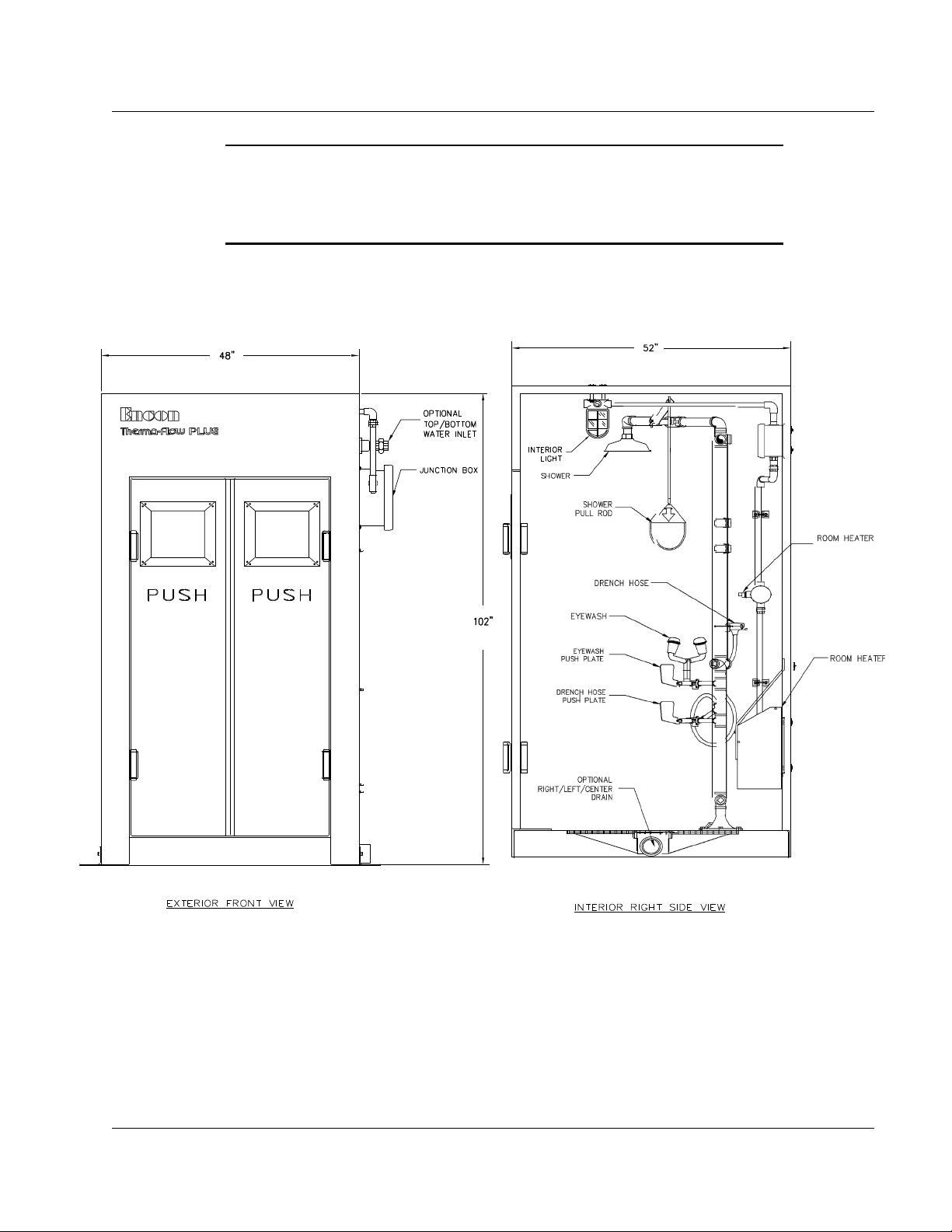
Figure 2-1.
Therma-Flow
®
Plus Shower and Eyewash

Therma-Flow® PLUS
IOM 09900002 Revision C 08/15/21
© 2021, Encon Safety Products, Inc.
2-3
2 INSTALLATION
2.3 Unpacking and Securing the Unit
Upon receipt of the equipment, verify the packaging and unit are received in
good order. Inspect the pipe connections and electrical unions to ensure they
are securely connected. Vibrations during shipment can loosen the pipes and
electrical fittings.
Using a forklift, lift the unit from the rear (opposite the shower room doors). The
load must be balanced and transported low to the ground. Use care to prevent
damage to decals or hardware on the unit.
If you are lifting the unit with a cherry picker or crane, spreader bars and slings
are recommended to prevent cracking the side walls.
To unpack and secure the unit:
1. Remove the ½" lag bolts from the mounting brackets that were used to
secure the unit to the wooden pallet.
2. Using a forklift, carefully insert the forklift prongs between the wooden skid
runners and lift the building off of the wooden pallet.
3. Place the building at the desired location for installation. Set the unit on a
pad, structural grate, or other suitable surface. Carefully and slowly remove
the forklift prongs.
4. Bolt the unit down using U-clamps (steel grate) or bolts (concrete) through
the pad eyes.
2.4 Connecting the Drain
Therma-Flow® Plus may require a drain pipe that will accommodate a 3” I.D. PVC
drain fitting extension for Right or Left Drain, or a 3” I.D. or 4” O.D. for a Center
Drain.
An external drainage system should be designed for a zero PSI drop gravity
drain with a 30 GPM (113.5 LPM) flow rate.
Ensure the drain connection is:
• Free flowing.
• Freeze protected (if applicable to the environment).
• Meets local and federal codes regarding water drainage.
Also consider that the water runoff may contain a substance or material which
may have the potential to cause harm to the environment. Choose an
appropriate location to drain the runoff according to the type of hazard being
irrigated.

2 INSTALLATION
2-4
2.5 Connecting the Water Supply
It is
recommended
you use potable water as the water supply. Encon® provides the
union connections to connect your water supply according to your specifications.
A minimum pressure of 30 PSI (206.8 kPa) at the input should assure proper water
flow pattern from the shower head. The input pressure cannot be more than 80 PSI
(551.5 kPa).
The water supply pipe must be sized to provide at least 30 GPM (113.5 LPM) water
flow. The supply pipe connected to Therma-Flow® Plus must be either
of the
same
material or of a material compatible with that of the unit to avoid corrosion. The use of
dissimilar metals in the supply pipe should be avoided as this could cause corrosion
throughout the system. Steel pipe or cast iron fittings should not be used unless they
are galvanized or otherwise protected from corrosion by potable water.
To connect the water supply to Therma-Flow® Plus:
1. Flush the water supply piping to remove pipe thread (metallic particulate
which may become stuck in flow switch or eyewash orifice) or calcium
carbonate from the supply line.
2. It is strongly recommended you install a strainer with a clean-out valve in the
supply line. Ensure the strainer-drain connection is free flowing and freeze
protected (if necessary).
3. It is recommended that you include an isolation valve on the supply pipe in an
accessible position to shut off the water supply during maintenance. The
isolation valve should have locking mechanisms to prevent unauthorized
shutoff and should be labelled accordingly.
4. Connect the water supply to the Therma-Flow® Plus union connections. If
your unit includes an underground extension, connect the water supply to the
extension (see “Figure 2-2. Underground Extension With and Without Flow
Switch.” on page 2-5).
2.6 Installing Area Locator and Alarm Lights (if applicable)
Your unit may have area and alarm light fixtures. These lights help a user locate the
emergency
station and provide constant
illumination
inside the unit. Typically, light
bulbs are not shipped with the unit by Encon®. However, the glass globe (clear,
green, blue, or red) and protective light guard are shipped with the
unit and
require
installation. Install the bulbs into the exterior and interior light fixtures, then install the
color or clear glass globe over the bulb by screwing it into the fixture grooves. Install
the protective light guard over the globe by screwing it into the fixture grooves. See
“Figure 2-3 Typical Light Fixture” on page 2-5.

2 INSTALLATION
2-5
Therma-Flow® PLUS
IOM 09900002 Revision C 08/15/21
© 2021, Encon Safety Products, Inc.
Figure 2-2. Underground Extension With and Without Flow Switch
Figure 2-3. Typical Light Fixture

2 INSTALLATION
2-6
2.7 Connecting the Electrical Power Supply
Refer to your local, state, provincial or federal regulations for the proper
grounding and electrical power connection.
CAUTION: Do not connect power prior to water connection (see “2.5
Connecting the Water Supply” on page 2-4).
To connect electrical power to the Therma-Flow® Plus:
1. Switch off the main electrical power supply.
2. It is highly recommended you install a circuit breaker at the electrical
power source for the incoming supply.
3. Insert the electrical power supply wires into the junction box and connect
them to the positive, negative, and neutral (ground) wires. Refer to the
typical electrical schematics Figure 2-4 or 2-5 on pages 2-7 and 2-8 to
make the proper connections.
4. Secure the electrical power supply inlet wires at the junction box fitting.
5. Switch on the main electrical power supply and test the unit. For more
information, see section “3 Operation and Testing” on page 3-1.
Therma-Flow® PLUS
IOM 09900002 Revision C 08/15/21
© 2021, Encon Safety Products, Inc.
2 INSTALLATION
2-7
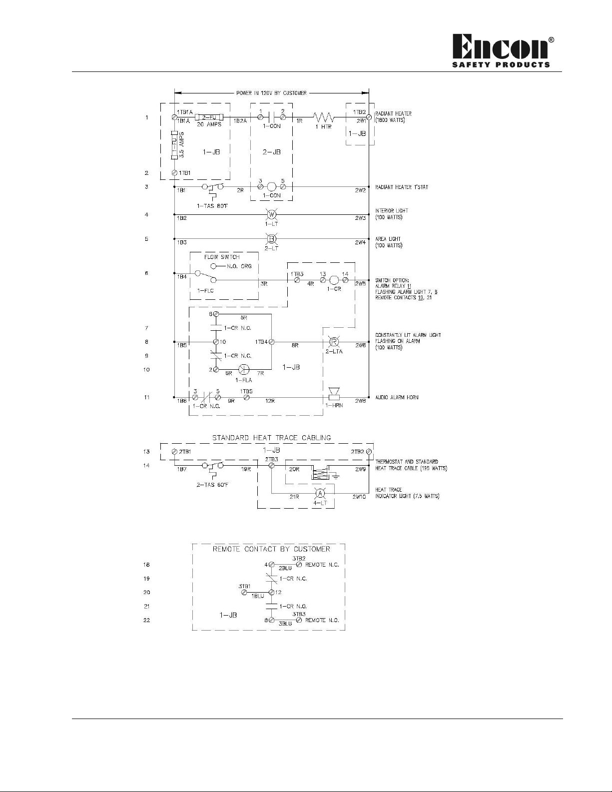
Figure 2-4 Electrical Schematic - Typical Therma-Flow® Shower with Flow Switch
Alarm and Enclosure Heater (120 Volt System)
Note: Options may vary, please refer to Electrical Schematic for your model.
2 INSTALLATION
2-8
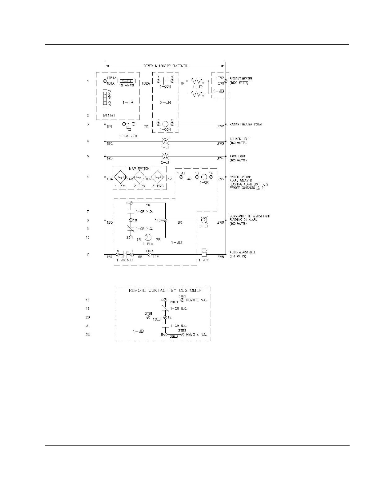
Figure 2-5 Electrical Schematic - Typical Galvanized Shower with MAP® Switch
Alarm and Enclosure Heater (120 Volt System)
Note: Options may vary, please refer to Electrical Schematic for your model.
2 INSTALLATION
Therma-Flow® PLUS
IOM 09900002 Revision C 08/15/21
© 2021, Encon Safety Products, Inc.
2-9
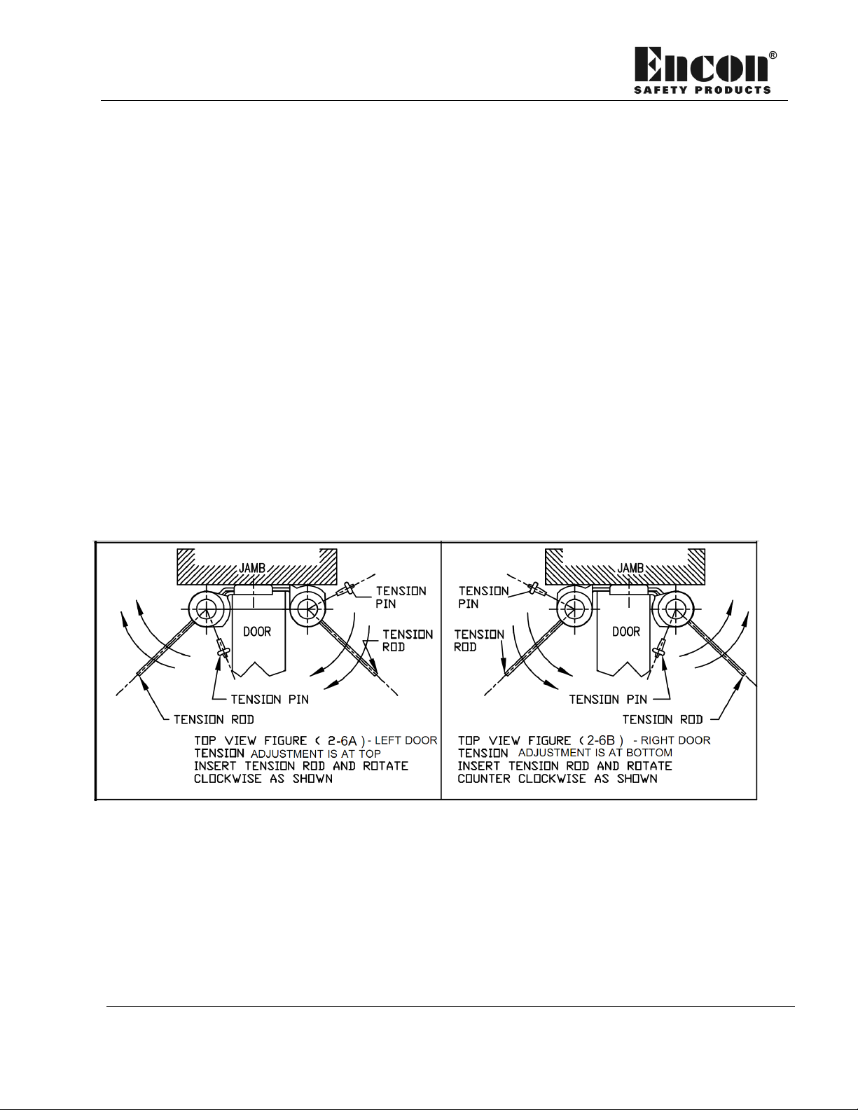
2.8 Adjusting the Enclosure Doors
Before shipping the unit to your location, Encon® sets the door springs to maximum
tension to prevent damage to the enclosure. You can adjust the spring tension so
that the doors will open and close easily. When you adjust the doors, ensure they
remain closed and there is enough resistance to prevent the wind
from opening them.
To adjust the door spring tension:
1. Insert a tension rod or 1/8” spring steel in the tension hole of the double acting
hinge.
2. Tighten the spring tension so that you can remove the tension pin.
3. Using the tension rod or drill bit, rotate the hinge in the direction of the arrow as
shown in Figure. 2-6. When you get the desired tension, re-insert the tension
pin and remove the tension rod or drill bit.
4. Repeat the procedure on all eight (8) adjustment points (four per door).
Figure 2-6. Setting the Door Hinge Tension.

3 OPERATION AND TESTING
3-1
3 OPERATION AND TESTING
3.1 Testing Therma-Flow® Plus
To perform a visual and operational inspection, complete the test items found in the
Therma-Flow® Plus Inspection Report form on page 3-4.
CAUTION: When using the Therma-Flow® Plus, the water may cause a slip hazard
in indoor installations and freezing slip hazards in outdoor installations.
3.2 Actuating and Stopping the Eyewash and Shower
The following procedures will operate the alarms (if applicable). If applicable,
notify the control room personnel that the alarms will operate due to testing. For
more information, see “4.9 Alarms (optional)” on page 4-14.
To actuate and stop the eyewash water flow:
1. To start the water flow, push down on the push plate or foot pedal (if
applicable).
2. To stop the water flow and alarms (if applicable), pull the push plate to its
original position.
CAUTION: Ensure the shower ball valve is completely closed. If it is allowed to
drip, it may freeze.
To actuate and stop the shower water flow:
1. Pull down on the pull rod.
2. To stop the water flow and alarms (if applicable), push up on the pull rod to its
original position

3 OPERATION AND TESTING
3-2
Therma-Flow® PLUS
IOM 09900002 Revision C 08/15/21
© 2021, Encon Safety Products, Inc.
CAUTION: Ensure the eyewash ball valve is completely closed. If it is allowed to
drip, it may freeze.
3.3 Testing the Eyewash
To test the eyewash:
1. Actuate the eyewash and check the eyewash flow pattern by inserting the eyewash
tester (Encon part number 01110469) into the dual stream
eyewash. The
stream
should meet the pattern design on the tester when lowered not more than 1½" (38.1
mm) from the point of initial contact. If the test fails, you
may need
to remove the
eyewash to remove an obstruction. For more information,
see “4.4 Dismantling and Reassembling the Eyewash and Drench Hose” on page 4-
3.
2. If applicable, ensure the alarms operate as designed.
3. Stop the water flow by pulling the push plate to its original position.
4. Ensure the eyewash completely drains. The three-way self draining eyewash requires
30 to 90 seconds to completely drain. Dripping from the bottom port at this time is
normal.
5. Reinstall the covers on the eyewash nozzle to prevent debris from entering the
eyewash nozzles. The covers also prevent shower water from entering the heads
and potentially freezing inside the eyewash.
6. Inspect the eyewash activation devices by doing the following:
a. Ensure they are securely fastened to the valve stem of the ball valves. b.
The valves must open and close in one second or less.
c. The valves must be drip free.

3-3
3 OPERATION AND TESTING
CAUTION: In freezing conditions, do not cover the eyewash nozzles until
draining is complete. If you put the covers on prematurely, the covers may
freeze and seal the eyewash heads to create a vacuum. As a result, the water
cannot drain and may freeze inside the eyewash.
3.4 Testing the Shower
To test the shower:
1. Open the shower valve and observe the water spray for the following:
a. Ensure the water is clear.
b. Ensure the pattern of water spray is a minimum 20" (508 mm) diameter
pattern from the shower head and 60" (1524 mm) at standing level. If the test
fails, you may need to remove the shower head to
remove
an obstruction.
2. If applicable, ensure the alarms operate as designed.
3. Stop the water flow and alarms (if applicable) by pushing up on the pull rod to its
original position
4. Inspect the shower activation devices by doing the following:
a. Ensure they are securely fastened to the valve stem of the ball valves.
b. The valves must open and close in one second or less.
c. The valves must be drip free.

3 OPERATION AND TESTING
3-4
Therma-Flow® PLUS
IOM 09900002 Revision C 08/15/21
© 2021, Encon Safety Products, Inc.
3.5 Therma-Flow® Plus Inspection Report
DATE
AREA
TAG
NUMBER
MODEL
NUMBER
SERIAL
NUMBER
I. VISUAL INSPECTION
UNIT VISIBILITY
ENCLOSURE PROVIDES A MIN. UNOBSTRUCTED AREA OF 34” (86.4 cm) IN DIAMETER
AREA FREE OF DEBRIS (Within 10 seconds from hazard, Out of potential spray path)
AREA LIGHT/ALARM LIGHT/INTERIOR LIGHT
SIGN CONDITION
EYEWASH COVERS ATTACHED AND IN PLACE ON NOZZLES
SHOWER POSITIONED TO PROVIDE FLUID PATTERN HEIGHT AT MIN. 82” – MAX. 96” FROM STANDING LEVEL
EYEWASH (Min. 33” – Max. 45” from standing level and min. 6” from nearest obstruction)
VALVES (q Leaking: Eyewash Shower Drench Hose)
ACTUATORS EASILY LOCATED AND READILY IDENTIFIABLE
PULL ROD NO GRATER THAN 69” FROM STANDING LEVEL
INSULATION AND COVERS (q Adjustment q Replacement)
HEAT TRACE INDICATOR LIGHT (q On q Off) if applicable
FREEZE / SCALD PROTECTION VALVES (q Leaking: F.P. Valve S.P. Valve)
OK NO
II. OPERATIONAL INSPECTION
SHOWER VOLUME (Min. 20 gpm / 75.7 lpm)
SHOWER PATTERN TEST (20” diameter pattern 60” from standing level)
SHOWER VELOCITY, NONINJURIOUS TO USER (q Too High q OK)
EYEWASH VOLUME (Min. 0.4 gpm / 1.5 lpm)
EYEWASH PATTERN TEST
EYEWASH VELOCITY, NONINJURIOUS TO USER (q Too High q OK)
STAY OPEN VALVES “OFF” TO “ON” IN ONE SECOND OR LESS COMPONENTS
OPERATE SIMULTANEOUSLY TO ANSI REQUIRMENTS
ALARM TEST Local: Shower q OK q No; Eyewash q OK q No; Drench Hose q OK q No
Remote: Shower q OK q No; Eyewash q OK q No; Drench Hose q OK q No
SUPPLY WATER PRESSURE (Min. 30 psig / 207 kPag):
WATER TEMPERATURE (78° to 92°F / 25.6° to 33.3°C):
OK NO
Comments:
Corrective
action required to the shower/shower parts to place unit in operational readiness state:
Action required other than to the shower/shower parts to correct operation:
Report sent to: q Maintenance for action q Record keeping

4 MAINTENANCE AND REPAIR
4-1
4 MAINTENANCE AND REPAIR
4.1 Scheduling Maintenance
It is recommended that you flush the unit at least once a week by running the
eyewash and shower. It is also recommended that you routinely complete the
checklist items in the “3.5 Therma-Flow® Plus Inspection Report” on page 3-4.
Also, at least once a year, the freeze and scald protection valves (if applicable)
should be removed and tested by cycling water through them. For complete
instructions on this procedure, see “4.6 Freeze and Scald Protection Valves” on
page 4-9.
4.2 Removing and Replacing ABS Covers to Access Components
(if applicable)
If a Therma-Flow® shower is present, the internal components are under ABS
plastic covers that help to freeze protect the system (see Figure 4-1 on page
4-2). The ABS covers are divided into segments so that you can easily remove
them to access the components for repairs.
The covers are held together by closure strips compressed at the flange area of
the cover. The closure strips are adjustable and can be opened using a blade
screw- driver and reinstalled by using pliers to compress them. The compo-nents
that pass through the removable covers are sealed with synthetic rubber seals
(grommets) that keep out water, gases, and moving air (a very important feature to
maintain freeze protection).
To remove the ABS covers:
1. Pull the neoprene (black) closure strips away from the flanged edge of the
covers.
2. Separate the covers at the segment line (gasket sealed at time of manufacture)
and remove them.
3. All items protruding through the covers, such as the eyewash yoke and push
plate(s), must be physically removed from the shower unit prior to cover
removal. For more information, see “4.4 Dismantling and Reassembling the
Eyewash and Drench Hose” on page 4-3.
Inspect the covers to ensure nothing is missing or broken and replace as required.
Table of contents
Other ENCON Industrial Equipment manuals

Popular Industrial Equipment manuals by other brands


PFT
PFT LOTUS XS operating manual

Nidec
Nidec Leroy-Somer TAL 047 Installation and Maintenance

schmersal
schmersal AZM400Z-ST2-I1-2P2P-T-E instructions

Schier Products
Schier Products GB-15 Installation, operation and maintenance guide

CommScope
CommScope FOSC-400A4 Installation instruction

rotork
rotork IW Series installation manual