rotork IW Series User manual

RG-INSTALL-009 / PUB027-027_0917 Page 1 of 15
Date 26/09/2017
Gearbox Installation Manual
Rotork Gears IW, MOW, MTW, IB and IS ranges
(Electronic copy available on www.rotork.com)
! This manual contains important safety information. Please ensure it is
thoroughly read and understood before installing the gearbox.
! This manual is produced to enable a competent person to install, operate,
adjust and inspect Rotork gearboxes. Only persons competent by virtue of
their training or experience should install, maintain and repair Rotork
gearboxes.
! The gearbox weight is recorded on the packaging and on a label attached to
the gearbox.
! WARNING: Gearbox may present an unbalanced load.
! WARNING: With respect to handwheel operation of Rotork gearboxes, under
no circumstances should any additional lever device such as a wheel-key or
wrench be applied to the handwheel in order to develop more force when
closing or opening the valve as this may cause damage to the valve and/or
gearbox or may cause the valve to become stuck in the seated/backseated
position.
! WARNING: Damage to protective coatings should be correctly rectified and
may invalidate warranty.

RG-INSTALL-009 / PUB027-027_0917 Page 2 of 15
Date 26/09/2017
Contents
1. Introduction............................................................................................................................................... 3
2. Health and Safety ..................................................................................................................................... 3
3. Storage ...................................................................................................................................................... 3
4. Unpacking ................................................................................................................................................. 3
5. Handling .................................................................................................................................................... 3
6. Installation & Maintenance of Worm Combinations ............................................................................. 4
6.1. Output Sleeve Removal, Machining and Re-Fitting ..................................................................... 4
Important Notes in Figure 2:........................................................................................................................... 4
6.2. Mounting to the Valve ..................................................................................................................... 6
6.3. Baseplate Thread Depths................................................................................................................ 7
6.4. Setting the Gearbox Stops to Suit the Valve (IW and MOW Only).............................................. 7
6.5. Worm Combination Maintenance................................................................................................... 8
7. Installation & Maintenance for Multi-Turn IB & IS Combinations........................................................ 9
7.1. Output Sleeve Removal, Machining and Re-Fitting ..................................................................... 9
7.2. Mounting to the Valve ................................................................................................................... 10
7.2.1. Gearboxes IB2 to IB13 and IS2 to IS13, IS15 and IS17. ..................................................... 11
7.2.2. Gearboxes IB14 and IS14, IS16, and IS18-IS21................................................................... 12
7.2.3. All IB and IS Gearboxes ........................................................................................................ 13
7.3. Maintenance Instructions for IB & IS Gear Operators................................................................. 13
8. Paint Repair Procedure.......................................................................................................................... 14
9. Reference ................................................................................................................................................ 14
10. Handwheel Types .............................................................................................................................. 15

RG-INSTALL-009 / PUB027-027_0917 Page 3 of 15
Date 26/09/2017
1. Introduction
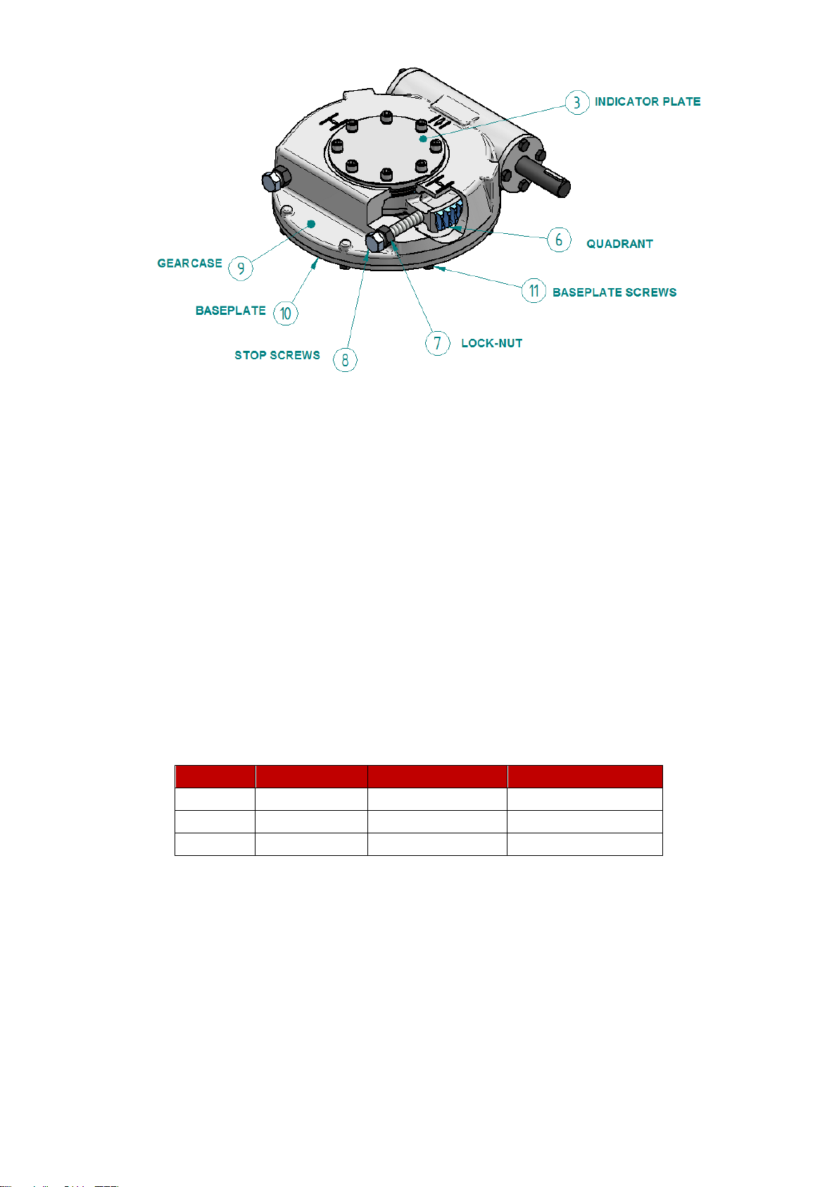
Unless otherwise specified the gearbox is supplied assembled. In the case of quarter turn gearboxes, the
gearbox stops have been set to a nominal 90° open and close position.
! The IW gearbox stops must be re-set for the stroke of the valve after combination installation.
2. Health and Safety
Work undertaken must be carried out in accordance with the instructions in this and any other relevant
manuals. The user and those persons working on this equipment should be familiar with their responsibilities
under any statutory provisions relating to the Health and Safety of their workplace. Due consideration of
additional hazards should be taken when using the gearbox with other equipment. Should further information
and guidance relating to the safe use of the Rotork products be required, it will be provided on request.
The mechanical installation should be carried out as outlined in this manual and also in accordance with
relevant standards such as British Standard Codes of Practice. No inspection or repair should be undertaken
unless it conforms to the specific hazardous area certification requirements. For maintenance of the actuator,
refer to the actuator installation and maintenance manual.
! WARNING: The gearbox enclosure materials may include cast iron, SG iron, carbon steel or
stainless steel.
3. Storage
If your gearbox cannot be installed immediately store it in a clean dry place until you are ready to install in
situ. Recommended storage temperature range: 0°C to 40°C (32°F –104°F).
4. Unpacking
Gearboxes are packed in a variety of configurations depending on size, type and quantity of the
consignment.
It is the responsibility of the individual unpacking and handling the combination to carry out a risk
assessment for the supplied arrangement to ensure safe working. Refer to Section 5 Handling.
Packaging material used may include wood, cardboard, polyethylene and steel. Packaging should be
recycled according to local regulations.
5. Handling
! Individual weights for gearboxes are recorded on their respective nameplates
! Only trained and experienced personnel should carry out handling. At all times, safe
handling must be ensured.
! Each combination must be assessed to identify all risks associated with handling.
! The gearboxes must be fully supported until full valve shaft/stem engagement is achieved
and the gearbox is secured to the valve flange.
! Once connected to the valve, each assembly must be assessed on an individual basis for
safe handling/lifting. Never lift the complete combination-valve assembly via the gearbox.
! If it is necessary to lift the gearbox using lifting equipment, certified soft slings are
recommended. Damage to protective coatings should be correctly rectified and may
invalidate warranty.
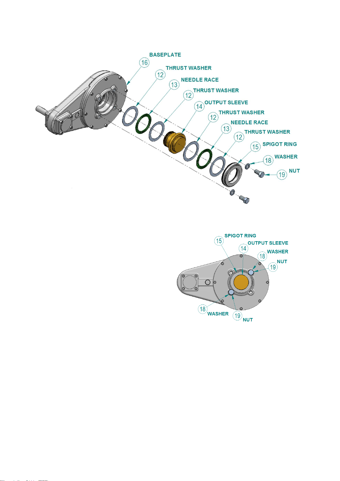
! We recommend fitting a bolt and washer system onto the baseplate of IB and IS gearboxes
before moving them, as demonstrated in Figure 7 and Figure 8.

RG-INSTALL-009 / PUB027-027_0917 Page 4 of 15
Date 26/09/2017
6. Installation & Maintenance of Worm Combinations
6.1. Output Sleeve Removal, Machining and Re-Fitting
Gearbox sizes IW12 to IW16 have an output which is directly machined as specified with the order. All other
worm gearbox combinations have a removable output sleeve. See Item 1, Figure 1.
Figure 1 shows the removal of the output sleeve from the gearbox. See Figure 2 for removing the output
sleeve without damaging the sealing faces.
Figure 1 - IW3-11 Output Sleeve Fitting
Figure 2 - IW Output Sleeve, Important Surfaces
Important Notes in Figure 2:
A: The surfaces marked ‘A’ are sealing or bearing faces and must not be damaged.
B: The surfaces marked ‘B’ can be used for chucking the output sleeve. *Note, this surface can
only be used for chucking on MTW gearboxes. NOT IW or MOW units.
C: To remove the output sleeve from the gearbox, a force may have to be applied to the face
marked ‘C’ of the output sleeve.
D: It is recommended to apply silicon sealant to the face marked ‘D’ when fitting the indicator
plate.
Unless specifically requested at the ordering stage, the output sleeve will be supplied blank and must be
machined to suit the valve shaft.
Referring to the item numbers in Figure 1, the output sleeve can be easily removed from the top of the
gearbox by first removing the retaining screws (5). The screws are either serrated under their heads or are
fitted with serrated washers (4). Then remove the indicator/cover plate (3).

RG-INSTALL-009 / PUB027-027_0917 Page 5 of 15
Date 26/09/2017
Figure 3 - O-Ring Inspection
Referring to Figure 3, O-rings (6) and (7) are to be inspected for damage, greased and properly seated
before re-fitting the output sleeve. If the O-ring is damaged then it should be replaced prior to fitting the
output sleeve.
! WARNING: Removing the retaining screws will result in the loss of control of the valve.
Referring to Figure 1, O rings (2) are used to seal the indicator plate, output sleeve and retaining screws.
Upon final installation on the valve, screws (5) must be tightened to the correct torque figures as shown on
the label on the underside of the indicator/cover plate.
Before re-fitting the output sleeve after machining, check that the surfaces marked ‘A’ in Figure 2 are not
damaged. Damaged surfaces can break the gearbox seals and cause water ingress or grease leakage.
Applying a thin layer of grease to the faces marked ‘A’ will make refitting of the sleeve easier.
As detailed in Figure 1 and Figure 2, it is recommended that silicon sealant is applied to face ‘D’ to seal the
indicator/cover plate to the output sleeve. Taking care not to apply sealant to the o rings (2) or the sealing
faces with the o rings.
Before re-assembly, clean and de-grease the top face of the output sleeve, underside of the indicator/cover
plate, and the socket head cap screws. Make a note of the tightening torque required for the output sleeve
screws on the label on the underside of the indicator plate. Insert the screws and washers into the holes in
the indicator/cover plate, as per Figure 1.
It is essential to fit the two part washers
the correct way round with the cam
faces of the washers joining. Place the
O-rings over the screw threads and
against the indicator plate.

RG-INSTALL-009 / PUB027-027_0917 Page 6 of 15
Date 26/09/2017
Apply a thin coat of silicon sealant to the top face of the output sleeve. Place the indicator on the output
sleeve, with the indicator pointer in the correct orientation if applicable. Engage each screw through the
indicator and output sleeve into the tappings in the gear quadrant. Fasten the screws evenly. As the screws
start to tighten, press down on the indicator plate to extrude any excess sealant. Wipe away the excess.
Tighten each screw to the recommended torque previously noted.
! WARNING: It is absolutely essential to assemble and torque tighten the screws immediately
after the sealant is applied to the indicator/cover plate and screws. Any delay will allow the
sealant to start to cure. This will result in a flexible joint being formed between the output
sleeve and indicator/cover plate. This joint would relax over time, allowing the screws to
loosen.
6.2. Mounting to the Valve
! WARNING: Ensure the valve is fully supported and capable of accepting increased weight
and change of centre of gravity resulting from the addition of the gearbox combination.
If the gearbox has been supplied with a handwheel, it is recommended that this be fitted to the gearbox
before mounting onto the valve. This will make it easier to rotate the gearing to pick up on the valve stem,
either key, flats or square.
1) Ensure gearbox output is in the same relative position as the valve shaft (open or closed). Gearbox
output position can be moved by rotating the input shaft or turning the actuator handwheel.
2) Apply a ring of silicone sealant around the mounting face of the flange, the ring should be at the
same radius from the shaft as the bolt holes Apply small rings of sealant around each of the bolt
holes to completely seal the faces (see Fig. 4)
Figure 4 - Sealing of Valve Mounting Flange
3) Align gearbox baseplate flange square and parallel to valve flange (see Figure 4), It is recommended
that flanges be sealed on assembly with silicon sealant. Grease the output sleeve and the valve
shaft.
4) Engage gearbox output sleeve onto the valve shaft ensuring the valve shaft keyway, square etc. is in
alignment (if necessary rotate output sleeve –refer to 1)
5) It is essential that the gearbox baseplate is flush with the valve bonnet flange before the mounting
screws are tightened. Mounting screws or studs/nuts must be high tensile steel (grade 8.8 or higher).
Firmly tighten down fixings onto the valve flange to the torque required. See Table 5 in section 9.

RG-INSTALL-009 / PUB027-027_0917 Page 7 of 15
Date 26/09/2017
6.3. Baseplate Thread Depths
Gearbox
Base
Min Thread
Depth
Max Drill
Depth
IW3 / MOW3
F/FA10, F/FA12
18
24
F/FA14, F/FA16
24
27
IW4 / MOW4
F/FA12, F/FA14
16
20
F/FA16
30
34
IW5 / IW52 / MOW5
F/FA14, F/FA16
20
25
F/FA25
16
20
F/FA25
30
34
IW6 / IW62 / IW63 /
MOW6
F/FA16, F/FA25
16
25
F/FA16, F/FA25, F/FA30
20
26
F/FA30
30
34
IW7 / IW72 / MOW7
F/FA16, F/FA30
24
29
F/FA30
24
28
F/FA35
30
40
IW8 / IW82 / MOW8
F/FA25, F/FA30, F/FA35, F/FA40
24-36
30-40
F/FA25, F/FA30, F/FA35
30
36
F/FA40, F/FA48
36
46
IW9 / MOW9
F/FA30, F/FA35, F/FA40
25-36
34-44
F/FA30, F/FA35, F/FA40
25-36
46
F/FA40, F/FA48
36
44
IW10 / MOW10
F/FA35, F/FA40
30-36
41-46
F/FA48
36
46
F/FA60
36
46
IW11 / IW11BB / IW115 /
IW115BB / MOW11
F/FA35, F/FA40, F/FA48
30-36
44
F/FA60
36
39
IW12 / IW13
F/FA40, F/FA48, F/FA60
38
48
F/FA48, F/FA60
38
48
Table 1 - Baseplate Mounting Hole Details
6.4. Setting the Gearbox Stops to Suit the Valve (IW and MOW Only)
This procedure should be carried out by the valvemaker/supplier and should be done when the valve
opening and closing operations can be visibly checked. Once installed within the pipe the stops should not
be altered without the authorisation of the valve maker/supplier.
The gearbox stops are factory set but require adjusting for optimum valve performance. If an actuator is to be
used to operate the gearbox, then the mating faces between the gearbox input flange and the actuator
output must be sealed prior to assembly using a ring of silicone sealant applied at the same radius as the
bolt holes, a small ring of sealant should be applied around each bolt hole to completely seal the faces (see
Figure 4). The actuator limit and torque switch settings should be set up according to the actuator
manufacturer's recommendations. The gearbox open & closed stop screws should then be set (see Figure
5).

RG-INSTALL-009 / PUB027-027_0917 Page 8 of 15
Date 26/09/2017
Figure 5 - Setting Stop-Bolts
Close the valve, using the actuator where applicable. Referring to Figure 5, use the indicator plate (3)
pointer as an indication of position.
Loosen the lock nuts (7) and turn the stop screws out approximately 3 complete turns, apply a small
amount of silicone sealant to the threads where the screws meet the gearcase. Operate the gearbox to
the closed position and screw in stop screw (8) until it touches the gearbox quadrant (6). Rotate the
screw back one turn, then tighten the lock-nut (7) to secure the stop screw. Open the valve with the
actuator, and then repeat the process with the open position stop screw. If the stop screws are re-
adjusted at a later date then silicone sealant must be re-applied.
Note –movement between baseplate (10) and gearcase (9) can occur when operating at near rated
torques. It is recommended that regular maintenance occurs to verify baseplate screws (11) are correctly
torqued.
6.5. Worm Combination Maintenance
Under normal operating conditions, no maintenance is required for the gearbox. Should the valve be taken
out of service for overhaul, the gearbox baseplate may be removed and the lubricant changed using one of
the lubricants in Table 2. The baseplate must be sealed using silicone sealant on re-assembly, unless fitted
with o-rings. These should be replaced.
Gearbox
Manufacturer
Name
Temperature Range
IW
Fuchs
Renolit CL-X2
-60°C to +120°C
MOW
Fuchs
Renolit LST 0
-20°C to +120°C
MTW
Fuchs
Renolit EPLITH 00
-10°C to +120°C
Table 2 - Recommended Lubrication for Worm Gearboxes
An equivalent extreme pressure lubricant may be used. For extreme temperature applications, please
consult Rotork Gears.

RG-INSTALL-009 / PUB027-027_0917 Page 9 of 15
Date 26/09/2017
7. Installation & Maintenance for Multi-Turn IB & IS Combinations
7.1. Output Sleeve Removal, Machining and Re-Fitting
IB and IS range of gearboxes have a removable output sleeve. Unless specifically requested at the ordering
stage, the output sleeve will be supplied blank and must be machined to suit the valve stem. Before re-fitting
the output sleeve after machining, check that the surfaces marked ‘A’ in Figure 6 are not damaged.
Damaged surfaces can break the gearbox seals or bearings and cause water ingress or grease leakage.
Figure 6 - Splined Output Sleeve - Important Surfaces
An anti-friction compound containing molybdenum disulphide, such as MI-Setral-9M should be applied to the
faces marked with ‘*’ and highlighted in red in Figure 6, before inserting the output sleeve back into the
gearbox. For clarification on the suitability of an anti-friction compound, please contact Rotork Gears.
Referring to Figure 7 below, note that the output sleeve arrangement is identical for IB and IS gearboxes.
The sleeve (14) can be easily removed from the gearbox by first removing the spigot ring (15) from the
baseplate (16). A small force may have to be applied to the face marked ‘C’ in Figure 6 to assist in removing
the sleeve.
! WARNING: It is imperative that the thrust bearings in the output are fitted correctly, along
with the output sleeve and the spigot ring. That is, the needle thrust bearings MUST have a
thrust washer (12) at each side of the needle race (13). A bearing / washer assembly MUST be
fitted at each side of the output sleeve thrust shoulder.
! WARNING: Bearings, Output sleeve and Valve Stem/shaft should be thoroughly greased with
appropriate grease before fitting anytime they are fitted into the gearbox/valve. Note the
spigot ring has an internal and external seal that should also be greased.

RG-INSTALL-009 / PUB027-027_0917 Page 10 of 15
Date 26/09/2017
The IB and IS output sleeves are splined and may have to be rotated slightly to engage with the mating
spline in the output gear.
Figure 7 - IB / IS Output Sleeve Assembly
! WARNING –We recommend fitting a
nut (19) and washer (18) fixture into the base
of the gearbox as demonstrated in Figure 7
and Figure 8. Note that the washers must
overlap the spigot ring (15). This will stop
the output sleeve assembly from becoming
detached from the main body. The bolts and
washers are not supplied by Rotork Gears.
If the gearbox has been supplied with a
handwheel, it is recommended that this be fitted
to the gearbox before mounting onto the valve.
This will make it easier to rotate the gearing to
pick up the valve stem, key, thread or spline
location.
Figure 8 - Securing Spigot Example
7.2. Mounting to the Valve
! WARNING: Ensure the valve is fully supported and capable of accepting increased weight
and change of centre of gravity resulting from the addition of the actuator-gearbox
combination. The recommended maximum unsupported length for cover tubes is shown in
table 3.
! WARNING: Bearings, Output sleeve and Valve Stem/shaft should be thoroughly greased with
appropriate grease before fitting into the gearbox/valve. Note the spigot ring has an internal
and external seal that should also be greased.

RG-INSTALL-009 / PUB027-027_0917 Page 11 of 15
Date 26/09/2017
7.2.1. Gearboxes IB2 to IB13 and IS2 to IS13, IS15 and IS17.
In addition to the points in Section 7.2.3, it is recommended that the machined output sleeve
assembly is assembled onto the valve stem first and then the gearbox lowered onto the output
sleeve assembly. See Figure 9 and Figure 10 for assembly details.
Figure 9 - Valve Stem Assembly
Figure 10 - Valve Stem (Assembled)
Fit the machined output sleeve (14), thrust bearings (12 & 13) and baseplate spigot ring (15) on the
valve shaft as shown in the Figure . Bearings should be lubricated with the appropriate grease (see
Table 4). Grease the bearings, output sleeve and valve stem. Note that the spigot ring has an
internal and external seal that should also be greased.
Figure 11 - Splined Output Sleeve - Important Surfaces
An anti-friction compound containing molybdenum disulphide, such as MI-Setral-9M should be
applied to the faces marked with ‘*’ and highlighted in red in figure 11, before inserting the output
sleeve back into the gearbox. For clarification on the suitability of an anti-friction compound, please
contact Rotork Gears.

RG-INSTALL-009 / PUB027-027_0917 Page 12 of 15
Date 26/09/2017
7.2.2. Gearboxes IB14 and IS14, IS16, and IS18-IS21
In addition to the points in Section 7.2.3, it is recommended that the cylindrical roller bearings and
machined output sleeve are assembled onto the valve stem first and then the gearbox lowered to
locate on the output sleeve assembly. See Figure12 for assembly details:
Figure 12 - Valve Stem Assembly with Cylindrical Roller Bearings
Fit in the following order:
oSpigot Ring,
oHousing Washer (Largest Outside Diameter),
oBearing
oShaft Washer (Smallest Outside Diameter),
oOutput Sleeve,
oShaft Waster (Smallest Outside Diameter),
oBearing
oHousing washer (Largest Outside Diameter)
The washer faces that are either chamfered or have markings MUST FACE AWAY from the
bearings to decrease wear on the bearing. Bearings should be lubricated with the appropriate
grease. Grease the output sleeve and valve stem. Note that the spigot ring has an internal and
external seal that should also be greased.
Figure 13 - Splined Output Sleeve - Important Surfaces

RG-INSTALL-009 / PUB027-027_0917 Page 13 of 15
Date 26/09/2017
An anti-friction compound containing molybdenum disulphide, such as MI-Setral-9M should be
applied to the faces marked with ‘*’ and highlighted in red in figure 13, before inserting the output
sleeve back into the gearbox. For clarification on the suitability of an anti-friction compound, please
contact Rotork Gears.
7.2.3. All IB and IS Gearboxes
Ensure that the gearbox baseplate is parallel to the valve flange when lowering. This will avoid
jamming.
It is recommended that a silicon sealant is used between the gearbox baseplate and the valve
flange. ‘D’ in Figure 4 highlights where this sealant should be applied.
When lowering the gearbox onto the valve rotate the handwheel to ensure the gearbox internal
splines correctly engage with the external splines on the output sleeve. Once engaged keep lowering
the gearbox until the valve and gearbox flanges are in contact. Align mounting base holes and
secure using screws or studs with a minimum tensile strength of 800 N/mm². Tighten fasteners onto
the valve flange to the torque required. See Table 5 in Section 9.
For rising stem valves, a cover tube must be fitted to protect the valve stem. ! WARNING: Do not
pack the cover tube with grease as this can lead to a pressure build up in the cover tube.
Screw or bolt the cover tube into the gearbox and seal with a suitable sealant to prevent water
ingress.
Cover tubes are extensions to the gearcase and thus, damage to the cover tube can cause damage
to the gearcase. It is essential that the cover tubes are protected or supported to avoid side loads as
a result of the environment or the application. See Table 3:
Gearbox
Maximum Unsupported Tube Length
IB3 to IB5, IS4 to IS5
2.0m (6.6ft)
IB6 to IB7, IS6 to IS7
2.8m (9.2ft)
IB8 to IB9, IS8 to IS9
3.0m (9.8ft)
IB10 to IB14, IS10 to IS20
5.0m (16.4ft)
Table 3 - Maximum Unsupported Tube Lengths
When an actuator is being installed to the input of the gearbox, it is important to apply a ring of
silicone sealant between the mating faces prior to assembly (see Figure 4).
7.3. Maintenance Instructions for IB & IS Gear Operators
For standard duties, all gear cavities are lubricated for life with Fuchs Renolit CL-X2 grease. Under normal
operating conditions, no maintenance is required for the gearbox. However, should the valve be taken out of
service for overhaul, the gearbox baseplate may be removed and the grease changed using the following
recommended lubricant. The baseplate must be sealed using silicone sealant on re-assembly, unless fitted
with an O ring. All O rings should be renewed.
An anti-friction compound containing molybdenum disulphide, such as MI-Setral-9M should be applied to the
faces marked with ‘*’ and highlighted in red in figure 9, before inserting the output sleeve back into the
gearbox. For clarification on the suitability of an anti-friction compound, please contact Rotork Gears.
Note: All thrust elements and bearing cavities must be re-greased and re-fitted in the correct order. The
recommended lubricant is shown in Table 4.

RG-INSTALL-009 / PUB027-027_0917 Page 14 of 15
Date 26/09/2017
Gearbox
Manufacturer
Name
Temperature Range
IB and IS
Fuchs
Renolit CL-X2
-60°C to +120°C
Table 4 - Recommended Lubrication for Bevel and Spur Gearboxes
An equivalent extreme pressure lubricant may be used. For extreme temperature applications, please
consult the factory.
8. Paint Repair Procedure
If paint repair is required, the following procedure should be followed:
Clean surface using solvent if necessary.
Rinse surface with clean fresh water to remove any foreign matter and traces of solvent.
Abrade area using wet and dry sandpaper, or power sander, feather edges of sound intact paint
around damaged area by 2.5 cm
Apply paint system as per originally applied to unit ensuring that dry film thickness (dft) limits are met
and time is allowed for each coat to cure. All as per the paint manufacturer’s data sheets.
Ambient Conditions - No cleaning or coating application shall be undertaken if:
The relative humidity is more than 85%
The metal temperature is less than 3ºC above the dew point.
The ambient conditions are outside those stated in the paint manufacturer’s data sheet for each
coating.
Coatings shall only be applied or cured at ambient and steel temperatures above 10ºC or otherwise
recommended by paint supplier.
9. Reference
Table 5 shows recommended tightening torques for mounting the gearbox to the valve.
Gearbox to valve fixing must conform to Material Specification ISO Class 8.8, yield strength 628N/mm² to
use Table 5 below:
Imperial
Size (Hex)
Torque
Metric Size
(Hex)
Torque
Nm
lbs/ft.
Nm
lbs/ft.
3/8”
34
25
M5
5
4
7/16”
55
40
M6
9
6
½”
83
61
M8
21
15
9/16”
120
89
M10
41
30
5/8”
166
122
M12
71
53
¾”
291
215
M16
177
131
7/8”
469
346
M20
346
255
1”
702
518
M24
598
441
1 ¼”
1403
1035
M30
1189
877
1 ½”
2441
1800
M36
2079
1533
Table 5 - Torque Tightening Figures

RG-INSTALL-009 / PUB027-027_0917 Page 15 of 15
Date 26/09/2017
10.Handwheel Types
Handwheel Type - Weight Kgs (lbs)
Size in mm
CD
(Cast)
PS
(Pressed
Steel)
SG
(Steel -
Welded)
S
(Stainless
Steel)
F/FS
(Steel -
Welded)
50
0.11 (0.24)
-
-
-
-
75
0.21 (0.46)
-
-
-
-
100
0.32 (0.71)
0.15 (0.33)
-
-
-
125
0.54 (1.19)
0.2 (0.44)
-
-
-
150
-
-
1 (2.20)
0.4 (0.88)
-
160
-
0.35 (0.77)
-
-
-
200
1 (2.20)
0.75 (1.65)
1.35 (2.98)
1 (2.20)
1 (2.20)
250
-
1.5 (3.31)
1.4 (3.09)
-
-
300
-
-
1.8 (3.97)
-
1.5 (3.31)
315
-
2 (4.41)
-
-
-
350
-
-
2.3 (5.07)
1.5 (3.31)
-
400
-
3.5 (7.72)
2.8 (6.17)
-
2.2 (4.85)
450
-
-
3 (6.61)
-
-
500
-
-
3.5 (7.72)
-
3 (6.61)
600
-
-
4.5 (9.92)
-
3.2 (7.05)
700
-
-
5 (11.02)
-
5.5 (12.13)
800
-
-
5.5 (12.13)
-
6.6 (14.55)
900
-
-
6 (13.23)
-
7.2 (15.87)
1000
-
-
-
-
8.4 (18.52)
1100
-
-
-
-
9.4 (20.72)
1200
-
-
-
-
10.27 (22.64)
Table 6 - Handwheel Weights by Type
This manual suits for next models
4
Table of contents
Other rotork Industrial Equipment manuals
Popular Industrial Equipment manuals by other brands

Tecnodue
Tecnodue I.T.S. PT 630 operating manual

KAKA Industrial
KAKA Industrial TR-40 Operation manual

Innotech
Innotech SYST-20-475-695 Series manual

A-PLUS AUTOMATION
A-PLUS AUTOMATION A3-P Instruction handbook

Grundfos
Grundfos IO 351 Installation and operating instructions

Trox Technik
Trox Technik TVRK Assembly and operating instructions