Yoshitake TRAP STAR TSF-10 User manual

EPDT-261f
PRODUCT MANUAL .
Thank you very much for choosing the Yoshitake’s product. To ensure the correct and safe use of the product,
please read this manual before use. This manual shall be kept with care for future references.
The symbols used in this manual have the following meanings.
Warning
This symbol indicates a potentially hazardous situation that, if not avoided,
could result in death or serious injury.
Caution
This symbol indicates a hazardous situation that, if not avoided, may result in
minor or moderate injury or may result in only property damage.
Table of Contents
1. Usage of the Product·················································· 1
2. Features ·································································· 1
3. Specifications···························································· 1
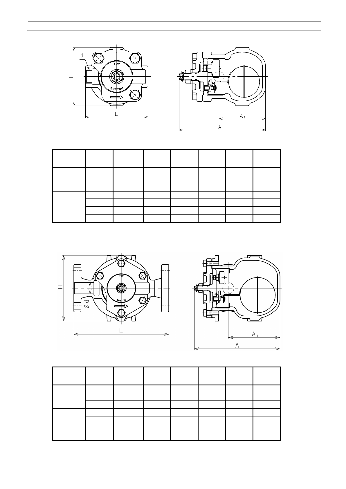
4. Dimensions and Weights············································· 2
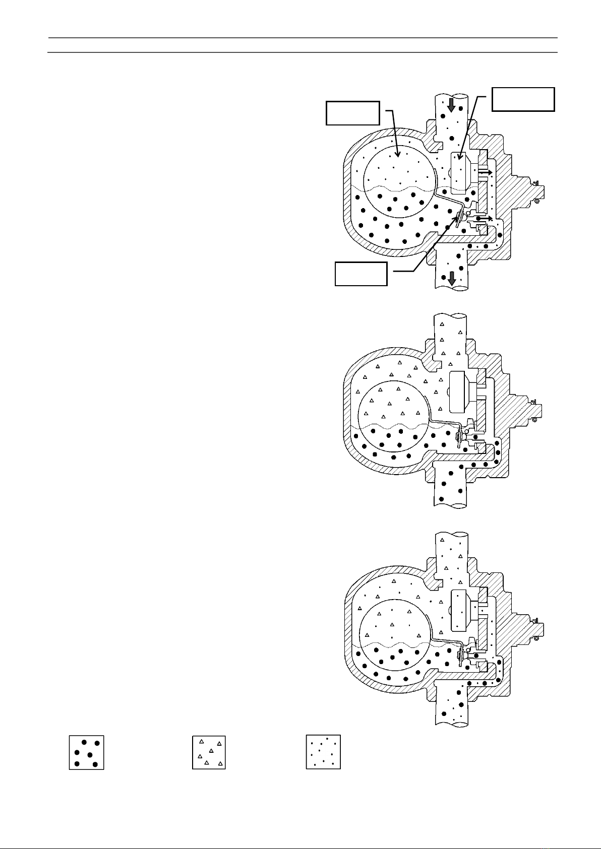
5. Operation ······························································· 3
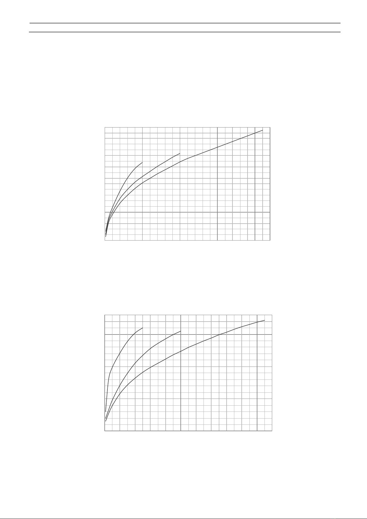
6. Maximum Continuous Discharge Capacity ······················ 4
7. Installation ······························································ 5
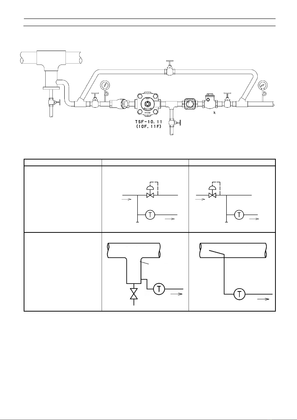
7.1 Piping example···················································· 5
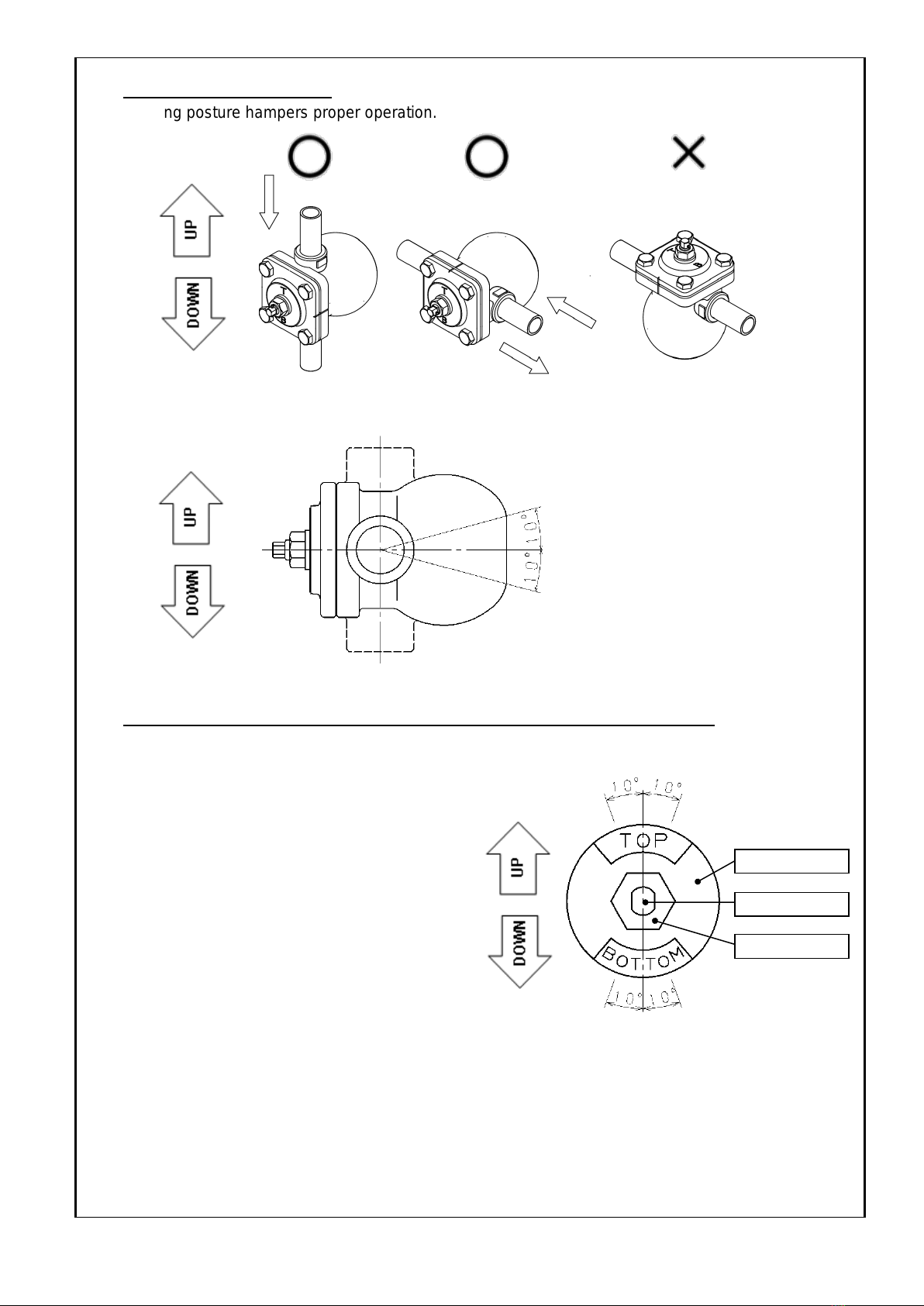
7.2 Precaution for installation······································· 7
8. Operating Procedure ·················································10
8.1 Precaution for operating procedure·························10
9. Maintenance ····························································11
9.1 Precaution for maintenance ··································11
9.2 Daily and periodic inspections ·······························12
9.3 Troubleshooting··················································13
9.4 Exploded drawing ···············································14
9.5 Disassembly ······················································15
9.6 Reassembly·······················································17
9.7 Parts replacement procedure ································20
Warranty Information
STEAM TRAP
MODEL TSF-10・11

1
1. Usage of the product
The TSF-10, TSF-10F, TSF-11, and TSF-11F can discharge condensate effectively without retention, and
realize energy saving steam system without steam loss. In addition, incorporated thermostatic air vent
discharges air inside the piping and shortens warming-up time. So, the product is suitable for steam equipments
used in various industries such as air-conditioning equipment, hot-water supply equipment, plant, and food.
2. Features
1. With turning the cock, it is possible to meet all flow directions (360 degrees) including horizontal or vertical
installation. Flow direction can be switched easily without disassembly such as detaching the cover.
2. Since the main parts are installed on the cover and it is possible to disassemble the cover with the body
installed on the piping, inspection and parts replacement can be conducted easily.
3. Compared to mechanical steam traps such as conventional float type or bucket type, the lower part
(dimension from the connection to the bottom) of the product is shorter. So, the product can be installed in
a low place such as condensate piping on low-floor equipment.
3. Specifications
Model
TSF-10
TSF-10F
TSF-11
TSF-11F
Nominal size
15A-25A
25A-50A
Application
Steam condensate
Working pressure
(Maximum working
differential pressure)
TSF-1-5: 0.01-0.5 MPa (0.5 MPa)
TSF-1-10:0.01-1.0 MPa (1.0 MPa)
TSF-1-21:0.01-2.1 MPa (2.1 MPa)
Max. temperature
220°C
Material
Body
Ductile cast iron
Float
Stainless steel
Valve,
valve seat
Stainless steel
Connection
JIS Rc screwed
NPT screwed
JIS 10K FF flanged
JIS 20K FF flanged
JIS Rc screwed
NPT screwed
JIS 10K FF flanged
JIS 20K FF flanged
Flow direction
All directions *
* For installation posture, see 3 of “7.2 Precaution for installation“ on Page 8.
Caution
Please confirm that the indications on the product correspond with the specifications
of the ordered product model before use.
* If they are different, do not use the product and contact us.

2
4. Dimensions and Weights
1. TSF-10 and TSF-11 Connection: JIS Rc screwed
TSF-10 (mm)
Model
Nominal
size
d
L
A
A1
H
Weight
(kg)
TSF-10
15A
Rc 1/2
121
167
90
113
3.6
20A
Rc 3/4
121
167
90
113
3.6
25A
Rc 1
145
167
90
113
4.0
TSF-11
25A
Rc 1
190
244
147
186
9.9
32A
Rc 1 1/4
190
244
147
186
10.0
40A
Rc 1 1/2
205
244
147
186
10.2
50A
Rc 2
220
244
147
186
10.5
2. TSF-10F and TSF-11F Connection: JIS 10/20K FF flanged
TSF-11 (mm)
Model
Nominal
size
d
L
A
A1
H
Weight
(kg)
TSF-10F
15A
15
175
167
90
113
5.0
20A
20
195
167
90
113
5.8
25A
25
215
167
90
113
7.1
TSF-11F
25A
25
270
244
147
186
13.4
32A
32
270
244
147
186
14.1
40A
40
280
244
147
186
14.4
50A
50
290
244
147
186
15.5

3
5. Operation
1.
At start-up, since the float is down, the valve is closed.
In this state, air in the system and piping is discharged
out through the air vent which is opened. When
condensate flows into the product, the float lifts up
and opens the valve, and then discharges
condensate. Air is continuously discharged out from
the air vent.
When steam flows into the product, internal pressure
of the air vent rises by steam temperature, and the air
vent closes. According to the amount of condensate
inflow, the float position moves up and down changing
the opening degree of the valve, and thus condensate
is continuously discharged. The float moves down
and the valve closes when condensate inflow stops.
When air or non-condensable gas flows into the
product, it accumulates in the upper part of the
product. When temperature of air or non-
condensable gas decreases with condensate
inflow, the air vent opens and discharges it to
outside of the product.
Then, operations 2 and 3 repeats according to the
inflow amount of condensate and air.
3. Air vent operation
2. Condensate discharging operation
1. Start-up of the operation
Float
Air vent
Valve
Air
Steam
Condensate

4
0
500
1000
1500
2000
0 0.5 1 1.5 2
排出量 (kg/h)
作動圧力差 (MPa)
TSF-10・10F 排出量線図
Working differential pressure (MPa)
TSF-10-10
TSF-10F-10
TSF-10-21
TSF-10F-21
TSF-10-5
TSF-10F-5
Discharge capacity (kg/h)
0
1000
2000
3000
0 0.5 1 1.5 2
排出量 (kg/h)
作動圧力差 (MPa)
TSF-11・11F 排出量線図
Working differential pressure (MPa)
TSF-11-5
TSF-11F-5
TSF-11-10
TSF-11F-10
TSF-11-21
TSF-11F-21
Discharge capacity (kg/h)
6. Maximum Continuous Discharge Capacity
1. Discharging capability of the steam trap differs by working differential pressure, that is, difference
between inlet pressure and outlet pressure (back pressure). In selecting discharge capacity,
consider outlet pressure. If inlet pressure is 0.5 MPa and outlet pressure is 0.2 MPa, discharge
capacity is of working differential pressure of 0.3 MPa.
2. The discharge capacity shown in the charts below is the maximum value. In designing a system, select a
steam trap with a sufficient safety factor (two times the regular level). That is, for example, if a discharge
capacity of 500 kg/h is required, select a steam trap capable of discharging more than 1,000 kg/h (maximum
discharge).
Maximum Continuous Discharge Capacity of TSF-10 and TSF-10F
Maximum Continuous Discharge Capacity of TSF-11 and TSF-11F

5
Steam main
Steam main
Drip leg
Trap
Stop
valve
Trap
7. Installation
7.1 Piping example
Description
Correct
Incorrect
If the product is installed close
to a regulating valve, make
sure to install the product at
the inlet side of the regulating
valve.
To discharge condensate from
the steam main, be sure to
install the product so that
condensate can be discharged
from the bottom of the steam
main by drip leg.
Regulating
valve
Regulating
valve
Drip
leg
Stop
valve
Stop valve
Stop valve
Pressure
gauge
Pressure
gauge
Sight
glass
Check
valve
Stop
valve
Stop valve
Strainer
Steam trap

6
Low
pressure
High pressure
Low pressure
High pressure
Description
Correct
Incorrect
Install the product below a
device which generates
condensate.
Install the products for each
device independently.
The diameter of collecting pipe
shall be more than summation
of sectional areas of discharge
pipes.
In addition, install check valves
for back flow prevention.
For condensate recovery,
connect the discharge pipe to
the upper part of collecting
pipe.
For traps of different pressure
lines, install collecting pipes
individually for each pressure.
In addition, install check valves
for back flow prevention.
* Re-evaporated steam in high
pressure line increases the back
pressure of low pressure trap.

7
Stop
valve
Stop
valve
By-pass valve
Stop
valve
Trap
Trap
Stop
valve
By-pass valve
Description
Correct
Incorrect
End portion of discharge pipe
shall be off the water surface in
the pit.
* If the discharge pipe is in contact
with the water, it absorbs dirty
water in the pit and causes
malfunction of the product.
Provide a by-pass line around
the product, and install stop
valves at the outlet side of the
product.
7.2 Precaution for installation
Caution
1. Before connecting the product to piping, remove foreign substances and scale from the piping.
* Failure to follow this notice may prevent the product from functioning properly.
* To plumb the product, be careful to keep seal materials from entering into the product.
2. To install the product, check the direction of the product so that the fluid flowing and the arrow marked
on the product are in the same direction.
* Setting the product in wrong directions prevents it from functioning properly.
3.Do not apply excessive load, torque or vibration to the valve.
* Doing so may result in malfunction or drastically shortened service life.

8
4. Check installation posture.
* Wrong posture hampers proper operation.
* Allowable tilt from horizontal line is within ±10°.
5. Adjust direction of the name plate in no pressure condition after installation.
* Do not turn the cock unless the pressure inside of the product and piping is completely discharged.
Forcing the cock to turn may result in damage to the cock.
* Wrong direction hampers proper operation.
* Fix the cock with spanner and loosen the
nut. Turn the cock and adjust direction of the
name plate to position "TOP" and "BOTTOM"
signs on upside and downside respectively.
Fix the cock with spanner and fasten the nut
after adjustment.
* Allowable tilt from vertical line is within ±10°.
6. Make sure to support the piping immovably.
* If an excessive piping stress is applied, the product may not open or close.
7. Do not disassemble the product unless it is necessary.
* Disassembly may prevent the product from functioning properly.
Name plate
Cock
Nut

9
8. Secure enough space for maintenance (such as cleaning of strainer), inspections and repair as
shown below.
* Failure to follow this notice prevents maintenance, inspection and repair.
TSF-10・10F
TSF-11・11F
9. Slope the piping and place the product at as a low position as possible in order to make condensate
flow into the product by its own weight.
10. To install the product in a main steam pipe, provide a drip leg at the inlet side of the product.
11. Install a strainer (mesh size of 80 or more is recommended) at the inlet side of the product.
12. Install the product so that it is not subjected to the shock of water hammer. Do not install a quick operating
valve before and/or after the product.
* Failure to follow this notice may result in malfunction due to damage to the float, or may result in scalds
or injury due to blow off when the product is subjected to an excessive shock and damaged.
13. Install a bypass line.
* The system has to stop operation while inspection and maintenance of the product if the bypass line is
not installed.
200 mm or more
300 mm or more

10
8. Operating Procedure
8.1 Precaution for operating procedure
Warning
1. Before leading fluid, make sure that the product is securely connected to piping and that there is no
loose.
* Failure to follow this notice may result in scalds or injury due to blow-off.
2. Do not touch the product with bare hands while the product operates.
* Failure to follow this notice may result in scalds.
3. Do not stand in front of the outlet opening of the product while the product operates.
* Failure to follow this notice may result in scalds or injury due to blow-off.
Caution
1. Slowly open each stop valve to prevent water hammer.
* Opening stop valves quickly may result in damage to other equipments due to hunting or water
hammer.
2. Do not turn the cock while the product operates.
* Do not turn the cock unless the pressure inside of the product and piping is completely discharged.
Forcing the cock to turn may result in damage to the cock.
* Wrong direction of the cock hampers proper operation.

11
9. Maintenance
9.1 Precaution for maintenance
Warning
1. Do not touch the product with bare hands.
* Failure to follow this notice may result in burns.
2. Completely discharge internal pressure of the product, piping and equipment, and cool down the
product prior to disassembly or maintenance.
* Failure to follow this notice may result in scalds or injury due to residual pressure.
Caution
1. Conduct daily inspection in order to maintain the optimal performance of the product.
* Failure to follow this notice may prevent the product from functioning properly.
* See “9.3 Troubleshooting” on Page 13 if trouble is observed.
2. After leaving the product not operated for a long period, perform inspection before start-up of operation.
* Failure to follow this notice may cause malfunction due to rust inside of the product and piping.
3. Put a container under the product at disassembly since condensate may flow out.
* Failure to follow this notice may result in making the surroundings dirty.
4. Be careful not to drop the parts at the time of disassembly. The disassembled parts should be placed
on soft cloth in order to avoid scratches and damage.
* Damage on the parts may cause malfunction and affect the optimal performance.
5. To assemble, connect all the parts securely and tighten the bolts uniformly in diagonal order.
* Failure to follow this notice may cause malfunction or outside leakage.
6. When repairing, do not use the parts other than the dedicated parts manufactured by Yoshitake. Do not
modify the product.
* Failure to follow this notice may cause damage to the product, or may result in scalds or injury due to
blow-off or malfunction.
7. In case of problems due to foreign substances or scale, the product needs repair or part replacement.
Please contact us for details.
(Please note that any repair due to foreign substances or scale in the product is subject to a charge
even during the warranty period.)

12
9.2 Daily and periodic inspections
Conduct daily and periodic inspections in order to maintain the optimal performance of the product.
See ”9.3 Troubleshooting”on Page 13 for the remedies if trouble is observed.
⚫Daily inspection (once a day)
Conduct daily inspection during operation of the product.
Items
Standards for Inspection
Discharge condition
of condensate
Condensate is discharged smoothly.
Outside leakage
No outside leakage of condensate or steam.
⚫Periodic inspection (once a year)
Conduct disassembly inspection periodically.
Items
Standards for Inspection
Seat surfaces of the
valve and valve seat
No scratch, abrasion, or foreign substances on seat surfaces.
Shape of float (P)
No deformation or damage on the float (P)
Dirt on the screen
No clogging on the screen

13
9.3 Troubleshooting
Trouble
Cause
Remedy
Condensate is not
discharged.
1. Blockage of foreign substances in
a discharge hole of the valve seat.
1. Disassemble and clean it.
2. The screen is clogging.
2. Disassemble and clean it.
3. The float (P) is damaged.
3. Replace it with a new one.
4. Breakage as a result of abnormal
pressure rising due to freezing or
water hammer, etc.
4. Replace the product with new one and
use it within the working pressure range.
5. Steam locking.
5. Change the piping system layout.
6. “TOP” and “BOTTOM” signs on
the name plate are in wrong
positions.
6. Adjust direction of the name plate to
position "TOP" and "BOTTOM" signs on
upside and downside respectively.
* See Caution No. 4, “7.2 Precaution for
installation” on Page 8.
Continuous blowout.
1. Foreign substances stuck on valve,
valve seat or air vent (P).
1. Disassemble and clean them.
2. Abrasion or scratches on the valve,
valve seat or air vent (P).
2. Replace the parts with new ones.
3. Insufficient capacity of the
product.
3. Replace the product with another model
of sufficient capacity.
4. “TOP” and “BOTTOM” signs on
the name plate are in wrong
positions.
4. Adjust direction of the name plate to
position "TOP" and "BOTTOM" signs on
upside and downside respectively.
* See Caution No. 4, “7.2 Precaution for
installation” on Page 8.
Steam leakage.
1. Leakage due to loosening of the
bolt.
1. Replace the cover gasket with new one,
and retighten the bolt.
2. Leakage due to deterioration of
cock gasket (P2) and O-ring.
2. Replace the parts with new ones.
3. Leakage as a result of abnormal
pressure rising due to freezing or
water hammer, etc.
3. Replace the product with new one and
use it within the working pressure range.

14
9.4 Exploded drawing
The parts shown in the rectangle boxes are available as consumable supply.
*The air vent (P) cannot be removed from the cock assembly.
*The plate cannot be removed from the cover.
Valve

15
9.5 Disassembly
⚫Tools to be used
Name of tool
Size (Nominal size)
Spanner
22 mm
Ring wrench
19 mm
[Procedure 1]
[Procedure 1]
Loosen the bolts fixing the cover with ring wrench (width across flat: 19
mm), and remove the cover and gasket from the body. Pull out the
screen from the body.
[Procedure 2]
Pull out the spindle from the float holder and remove the float (P)
assembly.
Spindle

16
[Procedure 4]
[Procedure 3]
Remove the split pin from the cock. With fixing the cock (width across
flat: 9 mm), remove the nut by using spanner (width across flat: 22 mm),
and then remove the collar and the name plate.
By pulling out the cock from the cover, the cock assembly can be
replaced.

17
9.6 Reassembly
⚫Tools to be used
Name of tool
Size (Nominal size)
Torque Wrench
* Tightenable with torque of 45 N・m
Width across flat: 19 mm
Torque Wrench
* Tightenable with torque of 35 N・m, Open-head type
Width across flat: 22 mm
Spanner
9 mm
Ring Wrench
22 mm
[Procedure 1]
[Procedure 2]
Check that the cock gasket (P1), plate, cock gasket (P2) and O-ring
(P11) are attached to the cock. Apply lubricant agent to the cock gasket
(P1) at its contacting surface with the cock (Recommendation:
SOLVEST No.110 paste, STT Inc.). Apply fluoro grease to the O-ring
(Recommendation: SOLVEST No.245, STT Inc.).
Attach the cock (after taking Procedure 1) to the cover. Check that the
cock gasket (P1) is attached to the cock properly. If not, it may cause
steam leakage to the outlet side.
WRONG
OK
The cock gasket (P1) is out
of the groove of the cock.
The cock gasket (P1) fits
in the groove of the cock.
O-ring
Cock gasket (P1)

18
Put the D-shaped
portion in the same
direction.
[Procedure 4]
[Procedure 3]
Attach the name plate, collar, and nut to the cock.
* When installing, match the holes on the name plate and collar with
shape of the cock.
Connect the float holder and float (P) assembly with the spindle. Check
that the float (P) assembly moves smoothly, and that the seat surface
of the valve is in contact with that of the valve seat.
OK
WRONG
The stopper is on the outer
circumference of the cock.
The stopper is on the center of
the cock.

19
[Procedure 7]
[Procedure 5]
[Procedure 6]
Attach the screen to the body. The screen can be inserted from either
end.
Install the cover gasket to the cover. Make the oval-shaped holes on
the cover and on the cover gasket in the same position. Make sure to
use a new cover gasket. Apply lubricant agent to the cover gasket
(Recommendation: SOLVEST No.110 paste, STT Inc.).
Install the cover to the body, making the oval-shaped holes on the cover
and on the body in the same position. Tighten the bolt with torque
wrench (width across flat: 19 mm) with torque of 45 N・m.
* Do not use impact wrench to tighten the bolt. Using it may cause
unevenly tightened bolt or damaged gasket, resulting in outside
leakage of condensate or steam.
Oval-shaped
hole
Make the oval-
shaped holes in the
same position.
Cover
Body
This manual suits for next models
3
Table of contents
Other Yoshitake Industrial Equipment manuals

Yoshitake
Yoshitake Trap Star TSF-8AT User manual

Yoshitake
Yoshitake SY-8 User manual

Yoshitake
Yoshitake TRAP STAR TSF-10CF User manual

Yoshitake
Yoshitake DS-1 User manual

Yoshitake
Yoshitake TRAP STAR TSF-11AT User manual

Yoshitake
Yoshitake SY-20-10 User manual

Yoshitake
Yoshitake SY-10 Series User manual

Yoshitake
Yoshitake TD-10NA User manual

Yoshitake
Yoshitake Trap Star TSF-13 User manual

Yoshitake
Yoshitake TRAP STAR TSF-12 Series User manual