Encore Medical Chattanooga Tru-Trac Model 4779 User manual

© 2006 Encore Medical, L.P.
Tru-Trac® Traction Unit- Model 4779
TX® Traction Unit- Model 4759
Applies to Serial numbers 1000 and above
SERVICE MANUAL
/
ISO 13485 Certified

Tru-Trac and TX® Therapeutic Traction Unit
FOREWORD.. .. .. .. .. .. .. .. .. .. .. .. .. .. .. .. .. .. .. .. .. .. 1
1 THEORY OF OPERATION.. .. .. .. .. .. .. .. .. .. .. .. .. 2
1.1 OVERVIEW . .. .. .. .. .. .. .. .. .. .. .. .. .. .. .. .. .. .. ..2
2 SAFETY PRECAUTIONS. .. .. .. .. .. .. .. .. .. .. .. .. 35
2.1 PRECAUTIONARY DEFINITIONS .. .. .. .. .. .. 3
2.2 PRECAUTIONARY INSTRUCTIONS .. .. .. . 35
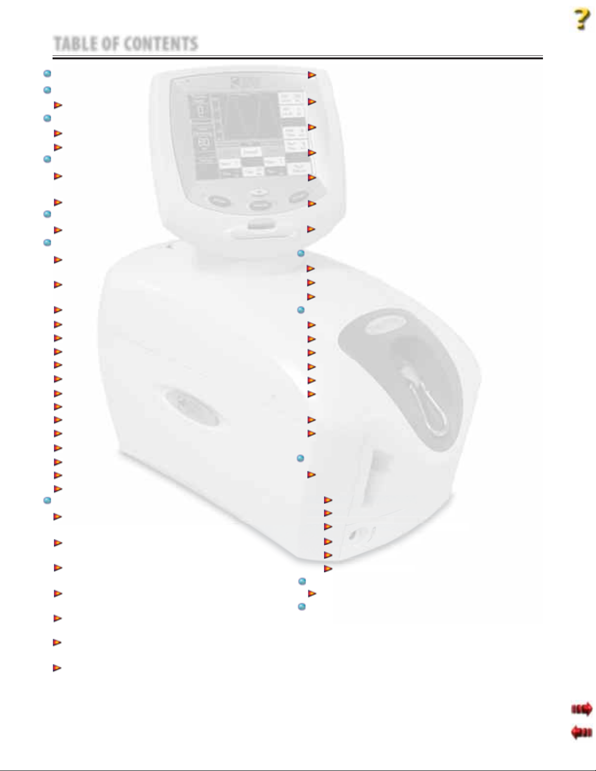
3 NOMENCLATURE .. .. .. .. .. .. .. .. .. .. .. .. .. .. .. .. .. 6
3.1 TRUTRAC AND TX UNIT
EXTERNAL COMPONENTS .. .. .. .. .. .. .. .. .. ..6
3.2 INTERNAL COMPONENTS .. .. .. .. .. .. .. .. .. ..7
4 SPECIFICATIONS .. .. .. .. .. .. .. .. .. .. .. .. .. .. .. .. .. 8
4.1 PHYSICAL SPECIFICATIONS .. .. .. .. .. .. .. .. ..8
5 TROUBLESHOOTING .. .. .. .. .. .. .. .. .. .. .. .. .. 926
5.1 TRUTRAC AND TX
ERROR MESSAGES.. .. .. .. .. .. .. .. .. .. .. ..9-13
5.2 TRUTRAC AND TX TRACTION UNIT
TESTING .. .. .. .. .. .. .. .. .. .. .. .. .. .. .. .. .. .. .. 14
5.3 VISUAL INSPECTION. .. .. .. .. .. .. .. .. .. .. .. 15
5.4 GROUND RESISTANCE TEST .. .. .. .. .. .. .. 15
5.5 LEAKAGE TESTS .. .. .. .. .. .. .. .. .. .. .. .. .. .. 15
5.6 ON/OFF SWITCH TEST . .. .. .. .. .. .. .. .. .. .. 16
5.7 ON/OFF SWITCH TROUBLESHOOTING . 16
5.8 PATIENT INTERRUPT SWITCH TEST . .. .. 17
5.9 CORD RELEASE AND RETRACT TEST.. .. 18
5.10 CORD RELEASE
TROUBLESHOOTING. .. .. .. .. .. .. .. .. .. 19-20
5.11 LOAD CELL TEST .. .. .. .. .. .. .. .. .. .. .. .. .. .. 21
5.12 LOAD CELL TROUBLESHOOTING .. .. 22-23
5.13 TOUCH SCREEN TEST .. .. .. .. .. .. .. .. .. .. .. 24
5.14 TOUCH SCREEN TROUBLESHOOTING .. 25
5.15 POWER SUPPLY TROUBLESHOOTING .. 26
6 REMOVAL & REPLACEMENT. .. .. .. .. .. .. .. .2751
6.1 SIDE COVER
REMOVAL & REPLACEMENT .. .. .. .. .. .. .. .. 27
6.2 TOP AND CORD GUIDE COVER
REMOVAL & REPLACEMENT .. .. .. .. .. .. .. .. 28
6.3 REAR COVER
REMOVAL & REPLACEMENT .. .. .. .. .. .. .. .. 29
6.4 FRONT COVER
REMOVAL & REPLACEMENT .. .. .. .. .. .. 30-31
6.5 MOTOR CONTROL BOARD
REMOVAL & REPLACEMENT .. .. .. .. .. .. .. .. 32
6.6 TOUCH SCREEEN ASSEMBLY
REMOVAL & REPLACEMENT .. .. .. .. .. 33-34
6.7 LOAD CELL ASSEMBLY
REMOVAL & REPLACEMENT .. .. .. .. .. 35-36
6.8 CLAMP SPRING ASSEMBLY
REMOVAL & REPLACEMENT .. .. .. .. .. .. .. 37
6.9 TRACTION CORD
REMOVAL & REPLACEMENT .. .. .. .. .. 38-43
6.10 CORD TENSION SPRING
REMOVAL & REPLACEMENT .. .. .. .. .. 44-45
6.11 SOLENOID ASSEMBLY
REMOVAL & REPLACEMENT .. .. .. .. .. .. .. 46
6.12 POWER SUPPLY
REMOVAL & REPLACEMENT .. .. .. .. .. 47-48
6.13 MOTOR ASSEMBLY
REMOVAL & REPLACEMENT .. .. .. .. .. 49-50
6.14 MOTOR DRIVE GEAR
REMOVAL & REPLACEMENT .. .. .. .. .. .. .. 51
7 CALIBRATION .. .. .. .. .. .. .. .. .. .. .. .. .. .. .. .. .5256
7.1 UNIT CALIBRATION .. .. .. .. .. .. .. .. .. .. .. 52-54
7.2 TOUCH SCREEN CALIBRATION .. .. .. .. .. .. 55
7.3 UNIT BURN IN . .. .. .. .. .. .. .. .. .. .. .. .. .. .. .. .. 56
8 PARTS.. .. .. .. .. .. .. .. .. .. .. .. .. .. .. .. .. .. .. .. .. .5764
8.1 TOP COVER ASSEMBLY .. .. .. .. .. .. .. .. .. .. .. 57
8.2 SIDE COVERS .. .. .. .. .. .. .. .. .. .. .. .. .. .. .. .. .. 58
8.3 FRONT AND REAR COVERS. .. .. .. .. .. .. .. .. 59
8.4 BASE AND EXTRUSION ASSEMBLY . .. .. .. 60
8.5 CHASSIS ASSEMBLY . .. .. .. .. .. .. .. .. .. .. .. .. 61
8.6 TRACTION CORD SPRING ASSEMBLY
AND POWER SUPPLY .. .. .. .. .. .. .. .. .. .. .. .. 62
8.7 SOLENOID AND CLAMP ASSEMBLIES .. .. 63
8.8 LARGE DRIVEN GEAR AND
SPOOL ASSEMBLY .. .. .. .. .. .. .. .. .. .. .. .. .. .. 64
9 SCHEMATICS . .. .. .. .. .. .. .. .. .. .. .. .. .. .. .. .. .6573
9.1 TRUTRAC AND TX TRACTION UNIT
SCHEMATICS .. .. .. .. .. .. .. .. .. .. .. .. .. .. .. 65-73
CONTROL BOARD . .. .. .. .. .. .. .. .. .. .. .. .. 66-68
MOTOR CONTROL BOARD . .. .. .. .. .. .. .. 69-70
PATIENT INTERRUPT SWITCH.. .. .. .. .. .. .. .. 71
SERIAL INTERFACE .. .. .. .. .. .. .. .. .. .. .. .. .. .. 72
SMART CARD .. .. .. .. .. .. .. .. .. .. .. .. .. .. .. .. .. 73
BLOCK DIAGRAM .. .. .. .. .. .. .. .. .. .. .. .. .. .. .. 74
10- SPECIAL FIXTURES. .. .. .. .. .. .. .. .. .. .. .. .. .. 75-78
CALIBRATION FIXTURE .. .. .. .. .. .. .. .. .. .. .. 75-78
11 WARRANTY . .. .. .. .. .. .. .. .. .. .. .. .. .. .. .. .. .. .. .79
TABLE OF CONTENTS

1
Tru-Trac andTX®TherapeuticTraction Unit
Read, understand, and follow the Safety Precautions and all other information contained in this
manual.
This manual contains the necessary safety and field service information for those field service
technicians, certified by Chattanooga Group, to perform field service on the Tru-Trac and TX unit.
At the time of publication, the information contained herein was current and up-to-date. However,
due to continual technological improvements and increased clinical knowledge in the field of
traction therapy, as well as Chattanooga Group’s policy of continual improvement, Chattanooga
Group reserves the right to make periodic changes and improvements to their equipment and
documentation without any obligation on the part of Chattanooga Group.
It is the sole responsibility for certified field technicians to stay informed and trained in the latest
technology utilized in the Tru-Trac and TX units by Chattanooga Group. From time to time, as
significant improvements are incorporated, service bulletins will be produced and made available
on our web site (chattgroup.com) in lieu of reprinting a complete manual prematurely. These service
bulletins will provide updated service information and technological improvements to the Tru-Trac
and TX unit for use by certified service technicians.
Due to the complex nature of the technology utilized by Chattanooga Group, the recommended
troubleshooting techniques are to determine “Bad Board” and board replacement only. No board
component level troubleshooting is recommended, nor will information or parts be supplied by
Chattanooga Group.
Any board component level troubleshooting performed will be at the sole risk and liability of the
certified field service technician performing such troubleshooting techniques. Performance of such
techniques may render the warranty null and void.
FOREWORD
©2006 Encore Medical Corporation or its affiliates, Austin, Texas, USA. Any use of editorial, pictorial, or layout composition of this publication without express written consent
from the Chattanooga Group of Encore Medical, L.P. is strictly prohibited. This publication was written, illustrated, and prepared for print by the Chattanooga Group of
Encore Medical, L.P.
Tru-Trac and TX® are prescription devices to be used only under the supervision of and by the order of a
physician or other licensed health care provider.

2
Tru-Trac andTX®TherapeuticTraction Unit
1 THEORY OF OPERATION
1.1 OVERVIEW
The Tru-Trac and TX traction unit is comprised of several pieces of proprietary hardware and software causing
the unit to function as required allowing administration of traction therapy under the prescription and
supervision of a licensed medical practitioner.
The Touch Screen Assembly houses the necessary hardware and software to communicate to the Motor
Control Board. Communicates commands and limits as established by the user through use of the Touch
Screen. The Touch Screen Assembly, in conjunction with the Motor Control Board, monitors the functionality
of the entire system during the course of the traction therapy being administered. Should the unit
malfunction or a communication error occur, the unit will stop treatment and generate an error message to
notify the operator of a possible problem.
The Touch Screen Assembly communicates to the Motor Control Board Assembly via a proprietary bus.
The Motor Control Board communicates to the Touch Screen Assembly throughout the therapy session all
parameters via feedback from the Motor Assembly and the Load Cell Assembly.
The Touch Screen Assembly incorporates a Patient Data Card Reader/Writer for the purpose of storing Patient
Treatment Data that can then be downloaded to a PC equipped with the optional PDMS System.

3
Tru-Trac andTX®TherapeuticTraction Unit
2 SAFETY PRECAUTIONS
The precautionary instructions found in this
section and throughout this manual are indicated
by specific symbols. Understand these symbols
and their definitions before operating this
equipment. The definition of these symbols are as
follows:
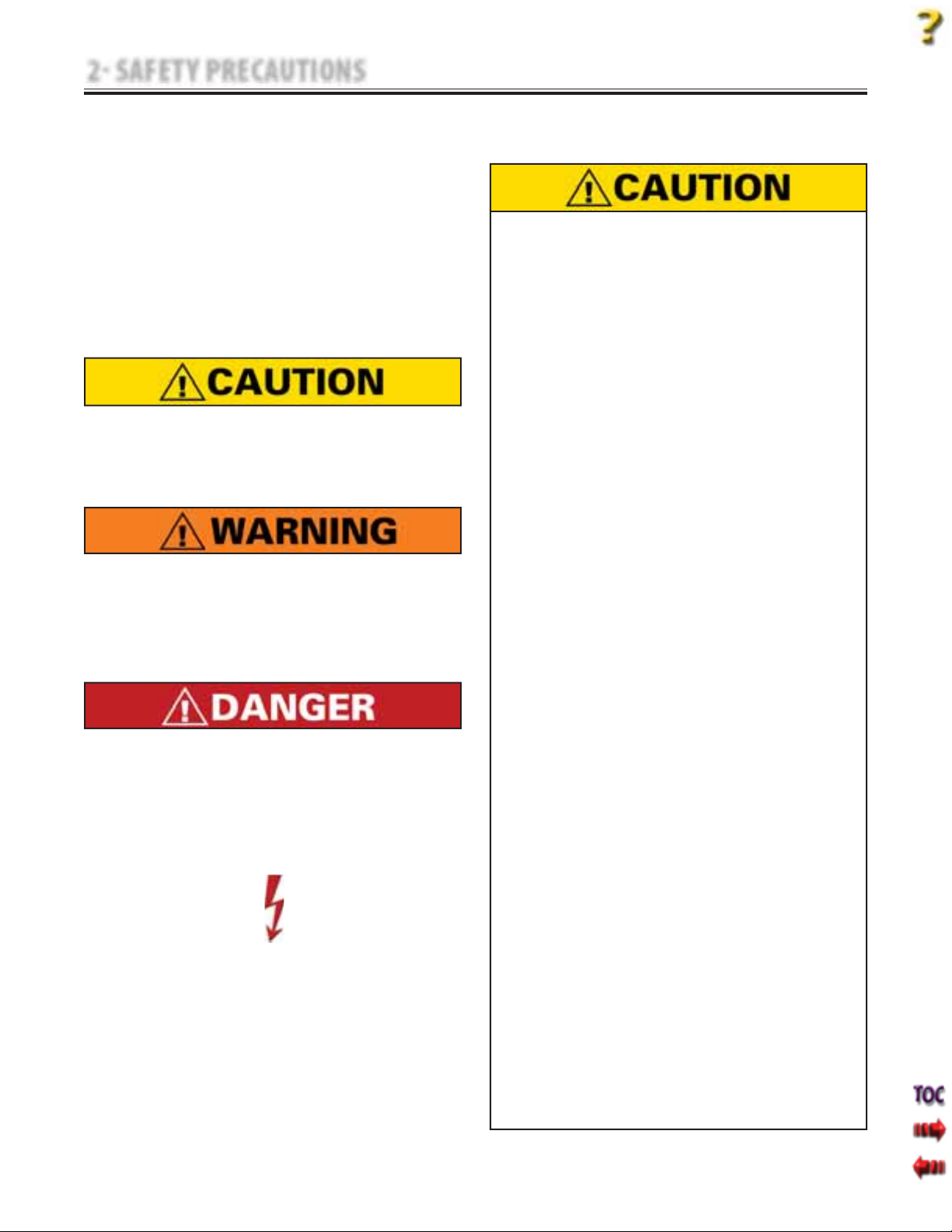
Text with a “CAUTION” indicator will explain
possible safety infractions that could have the
potential to cause minor to moderate injury or
damage to equipment.
Text with a “WARNING” indicator will explain
possible safety infractions that will potentially
cause serious injury and equipment damage.
Text with a “DANGER” indicator will explain
possible safety infractions that are imminently
hazardous situations that would result in death
or serious injury.
Text with a “Dangerous Voltage” indicator serves
to inform the technician of possible hazards
resulting in the electrical charge disbursement
from certain components if handled or serviced
improperly.
Throughout this manual, “NOTE” may be found.
These Notes are helpful information to aid in
the particular area or function being described.
2.1 PRECAUTIONARY DEFINITIONS
A. Caution
B. Warning
C. Danger
D. Dangerous Voltage
E. NOTE
2.2 PRECAUTIONARY INSTRUCTIONS
A. Cautions
Read, understand, and practice all precautionary
instructions found in this manual. Know the
limitations and hazards associated with using
any electrical traction device. Observe the
precautionary and operational decals placed on
the unit.
Do not use accessories other than those supplied
with the unit or recommended by Chattanooga
Group. The safety of other products has not been
established, and their use could result in injury to
the patient.
This unit should be transported and stored in
temperatures between 0°F and 140°F (-18°C
and 60°C) to prevent damage to the unit or its
components.
DO NOT operate this unit in an environment
where other devices are being used that
intentionally radiates electromagnetic energy in
an unshielded manner. Portable and mobile RF
communications equipment can affect Medical
Electrical Equipment.
This unit generates, uses, and can radiate radio
frequency energy and, if not installed and
used in accordance with the instructions, may
cause harmful interference to other devices
in the vicinity. However, there is no guarantee
that interference will not occur in a particular
installation. Harmful interference to other
devices can be determined by turning this (table,
unit, device, etc.) on and off. Try to correct the
interference using one or more of the following:
reorient or relocate the receiving device, increase
the separation between the equipment, connect
the equipment to an outlet on a different
circuit from that which the other device(s) are
connected and consult the Chattanooga Group
Service Department for help.
The unit should be routinely checked before each
use to determine all controls function normally.
Handle the unit with care. Inappropriate handling
of the unit may adversely affect its characteristics.
Before each use, inspect the Traction Cord for
wear. Prolonged wear on the cord will cause it to
break, which may cause sudden release of traction
pressure on a patient.
Test the Patient Interrupt Switch before each use
for power operation.
•
•
•
•
•
•
•
•
•

4
Tru-Trac andTX®TherapeuticTraction Unit
2 SAFETY PRECAUTIONS
2.2 PRECAUTIONARY INSTRUCTIONS (continued)
Do not remove the cover. This may cause unit
damage, malfunction, electrical shock, fire, or
personal injury. There are no user-serviceable parts
inside the unit. If a malfunction occurs, discontinue
use immediately, disconnect the Mains Power Cord
from the outlet, and consult the dealer for repair
service.
Do not use sharp objects such as a pencil point or
ballpoint pen to operate the buttons on the LCD
base as damage may result.
Do not permit any foreign materials or liquids
to enter the unit. Take care to prevent any
foreign materials including, but not limited to,
inflammables, water, and metallic objects from
entering the unit. These may cause unit damage,
malfunction, electrical shock, fire, or personal
injury.
Do not disassemble, modify, or remodel the
unit or accessories. This may cause unit damage,
malfunction, electrical shock, fire, or personal
injury.
Do not use the traction unit near devices such as
X-ray units or diathermy units. These units may
emit high frequency noise that may affect the
operation of the unit.
Failure to use and maintain the traction unit and
its accessories in accordance with the instructions
outlined in this manual will render the warranty
void.
In the event of a loss of power to the unit or
when quick release is needed, traction tension
should only be released by having the patient
move towards the traction head to release the
tension on the rope. Once the tension on the rope
has been released, loosen the patient harness
adjustment straps.
The tool, lubrication, and locking compound
requirements listed are critical to component
removal and replacement of the unit.
The hardware, bolts, nuts, and screws used to
assemble the Tru-Trac and TX are SAE and Metric.
Therefore, it will be necessary to obtain both SAE
and Metric tools for removal and replacement of
components.
The lubricant and locking compound listed are
crucial in the assembly of certain components to
ensure patient safety and efficient operation of the
unit.
•
•
•
•
•
•
•
•
•
•
Use of controls or adjustments or performance of
procedures other than those specified herein may
result in a hazardous traction related injury.
Before connecting the unit to an electrical outlet,
make certain the unit is electrically grounded by
connecting only to a grounded electrical service
receptacle conforming to the applicable national
and local electrical codes.
Do not use a damaged Mains Power Cord. Using
a damaged Mains Power Cord may cause unit
damage, malfunction, electrical shock, fire, or
personal injury. If the Mains Power Cord becomes
damaged, discontinue use immediately and contact
the dealer for replacement of the Mains Power Cord.
This device should be kept out of the reach of
children.
Always hand tighten the Lock Knob securely to
avoid any slippage.
Care must be taken when operating this unit,
adjacent to or stacked with other equipment.
Potential electromagnetic or other interference
could occur to this or other equipment. Try to
minimize this interference by not using other
equipment in conjunction with it.
In the event of a loss of power to the unit, traction
tension should only be released by gradually
lengthening the patient harness adjustment straps.
Dispose of all products in accordance with local and
national regulations and codes.
In the event that an Error message or Warning
appears beginning with a 2 or 3, immediately stop
all use of the system and contact the dealer or
Chattanooga Group for service. Errors and Warnings
in these categories indicate an internal problem
with the unit that must be tested by Chattanooga
Group or a Field Service Technician certified by
Chattanooga Group before any further operation or
use of the unit. Use of a unit that indicates an Error
or Warning in these categories may pose a risk of
injury to the patient, user, or may cause extensive
internal damage to the unit.
Unit failing Dielectric Withstand and/or Leakage
Tests could indicate serious internal problems.
DO NOT place the back into service! Send unit to
factory for repair! DO NOT attempt to repair the unit
in the field!
Unplug the unit from the power source before
attempting removal or replacement procedures to
prevent electrical shock.
When performing Unit Calibration Procedure, the
Calibration Fixture Load Cell must be set to US lbs.
•
•
•
•
•
•
•
•
•
•
•
•
B. Warnings

5
Tru-Trac andTX®TherapeuticTraction Unit
2 SAFETY PRECAUTIONS
2.2 PRECAUTIONARY INSTRUCTIONS (continued)
C. Dangers
DO NOT connect the unit to an electrical
supply without first verifying that the
power supply is the correct voltage.
Incorrect voltage may cause unit damage,
malfunction, electrical shock, fire, or
personal injury. Your unit was constructed
to operate only on the electrical voltage
specified on the Voltage Rating and Serial
Number Plate. Contact the Chattanooga
Group dealer if the unit is not properly
rated.
Power Supplies retain High Voltage!
Discharge the C4 Capacitor prior to
complete removal of the Power Supply.
Discharge the C4 Capacitor prior to
handling of the new Power Supply.
Tru-Trac and TX® is a prescription device to
be used only under the supervision of and
by the order of a physician or other licensed
health care provider.
Do not use any other knot styles in the
Cord other than those specified in this
manual. Use of other knot styles could
cause Cord to completely disengage from
the system and may cause serious injury
to patient and personnel.
•
•
•
•
•
•
Use only accessories that are specially designed
for this unit. Do not use accessories manufactured
by other companies on this (table, unit, device,
etc.). Chattanooga Group is not responsible for
any consequence resulting from using products
manufactured by other companies. The use
of other accessories or cables may result in
increased emissions or decreased immunity of
this (table, unit, device, etc.).
This component removal and replacement
procedure requires that the following be performed
after component or assembly replacement to
ensure proper alignment and operation of the unit:
COMPLETE CALIBRATION OF UNIT
Refer to Section 7
AND
MINIMUM OF 2 HOUR BURN IN OF UNIT AFTER
SUCCESSFUL CALIBRATION Refer to Section 7
Failure to perform either of these procedures, after
a component or assembly replacement will void
warranty and may result in injury to patients
and/or severe equipment damage.
It is not recommend tying a new knot in a cord that
has frayed or failed in use or is worn in an area from
constant use. The cord must be replaced.
•
•
•

6
Tru-Trac andTX®TherapeuticTraction Unit
The nomenclature graphics below, Figure 3.1,
indicate the general locations of the major external
components of the Tru-Trac and TX traction unit.
Know the components and their functions before
performing any operation of or service to the
Tru-Trac and TX traction unit.
FIGURE 3.1
1
2
3
4
6
7
3 NOMENCLATURE
3.1 TRUTRAC AND TX UNIT EXTERNAL COMPONENTS
5
Touch Screen Assembly
Top and Cord Guide Cover
Traction Cord Knuckle
Front Cover
Patient Interrupt Switch Receptacle
1.
2.
3.
4.
5.
Side Cover
Clamp Assembly Knob
Rear Cover
Mains Power Cord Receptacle
On/Off Power Switch
6.
7.
8.
9.
10.
8
9
10

7
Tru-Trac andTX®TherapeuticTraction Unit
3 NOMENCLATURE
3.2 INTERNAL COMPONENTS
FIGURE 3.2
1
2
3
4
5
6
The nomenclature graphics below, Figure 3.2,
indicate the locations of the major internal
components of the Tru-Trac and TX traction unit.
Know the components and their functions before
performing any operation of or service to the
Tru-Trac and TX traction unit.
7
8
9
10
11
12
Chassis
Load Cell
Top Front Traction Cord Guide
Traction Cord
Front Cover Mounting Bracket
Motor Control Board
1.
2.
3.
4.
5.
6.
Motor Assembly
Power Supply
Cord Tension Spring and Housing
Clamp Spring Assembly
Large Driven Gear
Solenoid Assembly
7.
8.
9.
10.
11.
12.

8
Tru-Trac andTX®TherapeuticTraction Unit
4.1 PHYSICAL SPECIFICATIONS
4 SPECIFICATIONS
Width . . . . . . . . . . . . . . . . . . . . . . . . . . . . . . . . . 24 cm (9.5 in)
Depth . . . . . . . . . . . . . . . . . . . . . . . . . . . . . . . 45 cm (17.5 in)
Height . . . . . . . . . . . . . . . . . . . . . . . . . . . . . . . 45 cm (17.5 in)
Weight
Standard Weight . . . . . . . . . . . . . . . . . . . . . . . .14 kg (30 lbs)
Shipping Weight . . . . . . . . . . . . . . . . . . . . . . . .18 kg (40 lbs)
Power
Voltage. . . . . . . . . . . . . . . . . . . . . . . . 100 V-240 V (50/60 Hz)
Power Consumption . . . . . . . . . . . . . . . . . . . . . . . . . . . 75 VA
Current Consumption . . . . . . . . . . . . . . . . . . . . . . 3.2 A Max
Electrical Class . . . . . . . . . . . . . . . . . . . . . . . . . . . . . . . . .Class I
Electrical Type . . . . . . . . . . . . . . . . . . . . . . . . . . . . . .Type B
Traction Modes. . . . . . . . . . . . . . . . . Static, Intermittent,
Cyclic, and their combinations.
Traction Type . . . . . . . . . . . . . . . . . . . . . . . . . . . Mechanical
LCD Display . . . . . . . . . . . . .High contrast monochrome
Touch Screen
Regulatory Compliance
Meets Directive 93 /42 /EEC
IEC/UL/EN: 60601-1 and 60601-1-2
CAN C22.2 No. 601.1-M90w/AZ
FIGURE 4.1
0413
TRACTION TENSION SPECIFICATIONS
PARAMETERS
PARAMETERS
MINIMUM
MINIMUM
MAXIMUM
MAXIMUM
INCREMENTS
INCREMENTS
Traction Period 1 minute 99 minutes 1 minute
Hold Period 0 seconds 99 seconds 1 second
Rest Period 0 seconds 99 seconds 1 second
Traction Tension 0 kg (0 lb/0 N) 90 kg (200 lb/890 N) 1 kg (1 lb/5 N)
Progrssive and
Regressive Steps
1 step 9 steps 1 step
HEIGHT
WIDTH
DEPTH

9
Tru-Trac andTX®TherapeuticTraction Unit
5.1 TRUTRAC AND TX ERROR MESSAGES
5 TROUBLESHOOTING
A. The following information is provided
as an aid in defining the Software Error
Messages of the Tru-Trac and TX traction unit.
Once a particular Error Message is defined,
the information will also list probable causes
and possible remedies. Once the problem
area is determined, subsequent tests for
verification will be necessary to determine
the subassembly or PC Board to be replaced.
In the case of PC Boards, all troubleshooting
and tests will be to validate a “Bad Board”
only. No component level troubleshooting
information is or will be provided by
Chattanooga Group for field troubleshooting
of PC board components.
B. Once a particular subassembly or PC Board
has been determined as bad, refer to the
appropriate Removal & Replacement
Section for the board affected and follow the
instructions for replacement of the board.
ERROR
CODE
ERROR
TYPE
DEFINITION PROBABLE CAUSES POSSIBLE REMEDY
USER CORRECTABLE WARNING MESSAGES
100 WARNING Treatment has been running for 8 seconds,
but no tension is detected on the Cord.
Too much slack in Traction Cord RemoveTraction Cord Slack.
101 WARNING Patient pressed Patient Switch. Patient Interrupt Switch button pressed. Touch the Touch Screen to clear message.
102 WARNING Patient Switch is unplugged. Patient Interrupt Switch not properly connected to unit. Properly connect Patient Interrupt Switch and touchTouch
Screen to clear message.
104 WARNING User selected Patient Card button on
utilities screen, but no traction treatments
were found on the card.
Wrong or bad Patient Data Card inserted into unit. Insert correct Patient Data Card.
105 WARNING User selected save to card, but no card is
inserted into the unit.
No Patient Data Card inserted. Properly insert correct Patient Data Card into unit.
106 WARNING User selected save to card, but the card
currently inserted is not a Patient Card.
Wrong or bad Patient Data Card inserted into unit. Insert correct Patient Data Card.
107 WARNING User selected save to card, but the card
currently inserted is full.
Memory full on Patient Data Card used. Save Data to PDMS and erase Patient Data Card.
108 WARNING User typed in a blank patient name. No Patient ID assigned. Enter Patient ID.
109 WARNING User typed in a blank protocol name. No Protocol name entered. Enter Protocol name.
110 WARNING User attempted to access a MMC function,
but no MMC is inserted into the unit.
No Multimedia Card (MMC) inserted into unit. Insert Multimedia Card (MMC) into unit.
111 WARNING User attempted to upgrade software, but
the MMC in the unit is not a software
upgrade MMC.
Wrong Multimedia Card (MMC) inserted into unit. Insert proper Mutimedia Card (MMC).
112 WARNING Error upgrading Control Board software. Unknown Contact Dealer or Chattanooga Group for Service.
113 WARNING Error upgrading motor board software. Unknown Contact Dealer or Chattanooga Group for Service.
114 WARNING User pressed START, but has not yet set
the Max Level value to a value greater
than zero.
User has not completed Treatment Set Up. CompleteTreatment Set Up prior to pressing START.
115 WARNING User pressed HOME button from treatment
review screen while a treatment was
running.
Home button has been pressed. Press STOP to end treatment prior to pressing HOME.

10
Tru-Trac andTX®TherapeuticTraction Unit
5 TROUBLESHOOTING
ERROR
CODE
ERROR
TYPE
DEFINITION PROBABLE CAUSES POSSIBLE REMEDY
ERROR MESSAGES (200-223) REQUIRING TECHNICAL ASSISTANCE
200 ERROR The motor PCB has reset. Motor Control Board is bad. If the Error repeats routinely, replace Motor Control Board.
201 ERROR Error communicating with the realtime clock
chip.
Control Board Communication Error. If the Error repeats routinely, replace Touch Screen Assembly.
202 ERROR The motor PCB returned an error while
performing the zero Load Cell function.
Bad Load Cell Assembly
Motor Control Board Communication Error.
1. Check Cables and Harnesses for proper seating and
connection on Motor Control Board.
2. Replace Load Cell Assembly.
3. Replace Motor Control Board.
4. ReplaceTouch Screen Assembly.
203 ERROR Timeout waiting for the motor PCB to perform
the zero Load Cell calibration.
Bad Load Cell
Bad Motor Control Board
1. Ensure there is slack in the Cord.
2. Check Cables and Harnesses for proper seating and
connection on Motor Control Board.
3. Replace Load Cell.
4. Replace Motor Control Board.
204 ERROR Timeout waiting for the motor PCB to perform
the motor current calibration.
Motor Control Board Communication Error. 1. Ensure there is no slack in the Cord.
2. Check Cables and Harnesses for proper seating and
connection on Motor Control Board.
3. Replace Load Cell.
4. Replace Motor Control Board.
205 ERROR A Motor fault error has occurred while a
treatment was running.
Internal mechanical jam of unit.
Bad Motor Control Board or Motor Assembly.
1. Correct any internal mechanical jam.
2. Replace bad Motor Control Board or bad Motor Assembly.
206 ERROR The Motor PCB cannot get to the desired tension. Internal Mechanical Jam of unit.
Bad Motor Control Board or Motor Assembly.
1. Correct any internal mechanical jam.
2. Replace bad Motor Control Board or bad Motor Assembly.
207 ERROR We have detected a motor current error
(MC_MON pin on motor PCB).
Unit out of calibration. Perform Unit Calibration and Burn In procedures.
208 ERROR We have detected a Load Cell limit error
(LC_MON pin on motor PCB).
Unit is out of calibration.
Bad Motor Control Board.
Bad Load Cell Assembly.
1. Perform Unit Calibration and Burn In procedures.
2. Replace Motor Control Board.
3. Replace Load Cell Assembly.
209 ERROR Error erasing a patient card. Bad Patient Data Card.
BadTouch Screen Assembly.
1. Try known good Patient Data Card.
2. Check Cables and Harnesses for proper seating and
connection on Motor Control Board.
3. ReplaceTouch Screen Assembly.
210 ERROR CRC not correct on treatment just read from
Patient Card.
Bad Patient Data Card.
BadTouch Screen Assembly.
1. Try known good Patient Data Card.
2. ReplaceTouch Screen Assembly.
211 ERROR Error reading default protocol on power up so
must rebuild protocols to factory presets.
EEPROM is corrupt. If the Error repeats routinely, replaceTouch Screen Assembly.
212 ERROR The Motor PCB flagged a comm watchdog error. Touch Screen Assembly did not poll Motor Control
Board in a reasonable amount of time.
1. Check Cables and Harnesses for proper seating and
connection on Motor Control Board.
2. If the Error repeats routinely, replaceTouch Screen
Assembly.
213 ERROR Motor PCB has indicated that the zero calibration
value is invalid and needs to be calibrated.
Unit is out of calibration. Perform Unit Calibration and Burn In procedures.
5.1 TRUTRAC AND TX ERROR MESSAGES (continued)
In the event that an Error message orWarning appears beginning with a 2 or 3, immediately stop all use of the unit and contact the dealer or Chattanooga
Group for service. Errors and Warnings in these categories indicate an internal problem with the unit that must be tested by Chattanooga Group or a Field
ServiceTechnician certified by Chattanooga Group before any further operation or use of the unit. Use of a unit that indicates an Error orWarning in these
categories may pose a risk of injury to the patient, user, or may cause extensive internal damage to the unit.

11
Tru-Trac andTX®TherapeuticTraction Unit
ERROR
CODE
ERROR
TYPE
DEFINITION PROBABLE CAUSES POSSIBLE REMEDY
ERROR MESSAGES (200-223) REQUIRING TECHNICAL ASSISTANCE (continued)
214 ERROR User has configured a treatment such that it takes
too much memory to compute the treatment
steps. Unit will default back to the default power
up protocol.
Under normal operating conditions, this Error should
never appear.
Remove unit from service and report exact treatment
parameters to Chattanooga Group.
215 ERROR Internal error, unit cannot get the next treatment
step information, treatment is terminated.
Multimedia Card (MMC) Data is corrupt.
Multimedia Card (MMC) interface not working.
1. Try known good Multimedia Card (MMC).
2. Remove unit from service and report exact treatment
parameters to Chattanooga Group.
217 ERROR Error reading a MMC. Bad Mutimedia Card (MMC).
Improper cable connection to Motor Control Board.
BadTouch Screen Assembly.
1. Try known good Multimedia Card (MMC).
2. Check Cables and Harnesses for proper seating and
connection on Motor Control Board.
3. ReplaceTouch Screen Assembly.
218 ERROR Error upgrading Control Board software. Bad Mutimedia Card (MMC).
Improper cable connection to Motor Control Board.
BadTouch Screen Assembly.
1. Try known good Multimedia Card (MMC).
2. Check Cables and Harnesses for proper seating and
connection on Motor Control Board.
3. ReplaceTouch Screen Assembly.
219 ERROR Error upgrading Control Board software. Bad Mutimedia Card (MMC).
Improper cable connection to Motor Control Board.
BadTouch Screen Assembly.
1. Try known good Multimedia Card (MMC).
2. Check Cables and Harnesses for proper seating and
connection on Motor Control Board.
3. ReplaceTouch Screen Assembly.
220 ERROR Error upgrading Motor Control Board software. Bad Mutimedia Card (MMC).
Improper cable connection to Motor Control Board.
Bad Motor Control Board.
BadTouch Screen Assembly.
1. Try known good Multimedia Card (MMC).
2. Check Cables and Harnesses for proper seating and
connection on Motor Control Board.
3. Replace Motor Control Board.
4. ReplaceTouch Screen Assembly.
221 ERROR Error upgrading Motor Control Board software. Bad Mutimedia Card (MMC).
Improper cable connection to Motor Control Board.
Bad Motor Control Board.
BadTouch Screen Assembly.
1. Try known good Multimedia Card (MMC).
2. Check Cables and Harnesses for proper seating and
connection on Motor Control Board.
3. Replace Motor Control Board.
4. ReplaceTouch Screen Assembly.
222 ERROR Patient switch is shorted. Patient Interrupt Switch not completely seated in
connector.
Bad Patient Interrupt Switch.
Bad Patient Interrupt Switch Connector.
1. Properly connect Pateint Interrupt Switch to unit.
2. Use a known good Pateint Interrupt Switch.
3. Replace Patient Interrupt Switch Connector on unit.
223 ERROR Beta version evaluation period has expired. Unit is designated BETA Test Unit. Immediately return unit to Chattanooga Group.
5.1 TRUTRAC AND TX ERROR MESSAGES (continued)
In the event that an Error message orWarning appears beginning with a 2 or 3, immediately stop all use of the unit and contact the dealer or Chattanooga
Group for service. Errors and Warnings in these categories indicate an internal problem with the unit that must be tested by Chattanooga Group or a Field
ServiceTechnician certified by Chattanooga Group before any further operation or use of the unit. Use of a unit that indicates an Error orWarning in these
categories may pose a risk of injury to the patient, user, or may cause extensive internal damage to the unit.
5 TROUBLESHOOTING

12
Tru-Trac andTX®TherapeuticTraction Unit
ERROR
CODE
ERROR
TYPE
DEFINITION PROBABLE CAUSES POSSIBLE REMEDY
CRITICAL ERRORS (300-314) DEMANDING TECHNICAL SERVICE
300
through
307
CRITICAL
ERROR
Communication Error betweenTouch Screen and Motor
Control Board.
Communication Error. 1. Check Cables and Harnesses for proper seating and
connection on Motor Control Board.
2. Replace Motor Control Board.
3. ReplaceTouch Screen Assembly.
308 CRITICAL
ERROR
We are supposed to be increasing tension, but tension
is not increasing.
Slack in Cord.
Bad Load Cell.
Bad Motor Control Board.
1. Remove slack in Cord.
2. Check Cables and Harnesses for proper seating and
connection on Motor Control Board.
3. Replace Load Cell.
4. Replace Motor Control Board.
309 CRITICAL
ERROR
We are supposed to be decreasing tension, but tension
is actually increasing.
Unit out of calibration.
Bad Harness connection.
Bad Load Cell.
Bad Motor Control Board.
1. Perform Unit Calibration and Burn In procedures.
2. Check Cables and Harnesses for proper seating and
connection on Motor Control Board.
3. Replace Load Cell.
4. Replace Motor Control Board.
310 CRITICAL
ERROR
We are reading > 0 tension when we should be
reading zero.
Unit out of calibration. Perform Unit Calibration and Burn In procedures.
311 CRITICAL
ERROR
We are reading < 0 tension when we should be
reading zero.
Unit out of calibration.
Bad Load Cell.
Bad Motor Control Board.
1. Perform Unit Calibration and Burn In procedures.
2. Check Cables and Harnesses for proper seating and
connection on Motor Control Board.
3. Replace Load Cell.
4. Replace Motor Control Board.
312 CRITICAL
ERROR
We have detected that the motor is running too fast. Bad Motor Control Board.
Bad Motor Assembly.
1. Replace Motor Control Board.
2. Replace Motor Assembly.
313 CRITICAL
ERROR
Internal memory error. BadTouch Screen. ReplaceTouch Screen Assembly.
314 CRITICAL
ERROR
Error reading EEPROM. BadTouch Screen. Cycle power to unit. If the Error repeats, then replace
Touch Screen Assembly.
5 TROUBLESHOOTING
5.1 TRUTRAC AND TX ERROR MESSAGES (continued)
In the event that an Error message orWarning appears beginning with a 2 or 3, immediately stop all use of the unit and contact the dealer or Chattanooga
Group for service. Errors and Warnings in these categories indicate an internal problem with the unit that must be tested by Chattanooga Group or a Field
ServiceTechnician certified by Chattanooga Group before any further operation or use of the unit. Use of a unit that indicates an Error orWarning in these
categories may pose a risk of injury to the patient, user, or may cause extensive internal damage to the unit.

13
Tru-Trac andTX®TherapeuticTraction Unit
NOTES

14
Tru-Trac andTX®TherapeuticTraction Unit
5.2 TRUTRAC AND TX TRACTION UNIT TESTING
5 TROUBLESHOOTING
A. General- Electronic
1. Information within this section in respect to
electronic components is intended to aid
in troubleshooting the PCB's of the Tru-Trac
and TX units to “Board Level” only.
These tests are the standard testing
procedures and methods used at the factory
before shipment of the unit.
2. Due to the complex nature of the technology
utilized by Chattanooga Group, the
recommended PCB troubleshooting
techniques are to determine “Bad Board” and
board replacement only. No PCB
component level troubleshooting is
recommended nor will information or parts
be supplied by Chattanooga Group. Any PC
board component level troubleshooting
performed will be at the sole risk and liability
of the Service Technician performing such
troubleshooting techniques.
3. Once a particular PCB has been
determined as bad, replace the PCB. Use
only Chattanooga Group replacement parts
and hardware.
B. General- Replacement Components
Critical component replacement parts for the
traction unit are available as subassemblies only.
This is due to the accuracy required and the
critical nature of the subassembly within the
unit for power function and operation. Individual
components of these subassemblies will not be
made available by Chattanooga Group.
C. General- Tests and Repair Procedures
1. Certain tests and repair procedures require
the use of special tools and/or fixtures.
These will be listed at the particular test
where they are required. Testing with any
other special tool or fixture other than those
stated could give erroneous readings or test
results. Always perform the tests exactly as
stated to ensure accurate results.
2. Test equipment settings will be listed for
each test performed prior to the respective
test to ensure the test is performed to
Chattanooga Group standards and ensure
power readings.
3. The troubleshooting and repair of the
units are to be performed only by authorized
technicians trained and certified by
Chattanooga Group.
D. Tools, Fixtures, and Equipment Required
1. Dielectric Withstand (Hi-Pot) and ground
resistance tester.
NOTE:
Adjust Dielectric Withstand tester to indicate fault with
120 kOhm load across the output when at specified
test voltage.
2. Milliohm Meter
3. Digital Multimeter
4. Required Hand Tool
#1 Phillips Screwdriver
#2 Phillips Screwdriver
Flat Blade Screwdriver
Calibrated Torque Wrench- 200 inch
pound or 2,500 Newton meter minimum
capacity.
Allen Wrenches
SAE- 3/32, 5/32, and 9/64 in
Metric- 3 mm
Hex Key Sockets for Torque Wrench
SAE- 3/32 and 5/32 in
Metric- 4 mm
Needle Nose Pliers
Tape Measure- 12 ft (3 meter) minimum
Ratchet
7mm Box End Wrench
Pick for removing connector wires.
5. Touch Screen to Cover Assembly Jig
6. Calibration Fixture with calibrated Strain
Meter.
7. Solenoid Assembly Mounting Jig. P/N 48139.
•
•
•
•
•
•
•
•
•
•
•
•
•
•
•
The tool, lubrication, and locking compound
requirements listed are critical to component
removal and replacement of the unit.
The hardware, bolts, nuts, and screws used to
assemble the Tru-Trac and TX are SAE and Metric.
Therefore, it will be necessary to obtain both SAE
and Metric tools for removal and replacement of
components.
The lubricant and locking compound listed are
crucial in the assembly of certain components to
ensure patient safety and efficient operation of the
unit.

15
Tru-Trac andTX®TherapeuticTraction Unit
5 TROUBLESHOOTING
5.3 VISUAL INSPECTION
A. General
Visually inspect the unit. A visual
inspection can, to an experienced Technician,
indicate possible abuse of the unit and
internal problems.
5.4 GROUND RESISTANCE TEST
A. Voltage Specifications
Models 4759 and 4779 . . . . . . . . .
Input: 100-240 VAC
50/60 Hz, 75 VA
B. Specification
Maximum Acceptable Resistance: 100 milliohms
C. Equipment Required
Milliohm Meter
D. Test
Place unit on level work surface.
Place one meter probe on the ground prong of
power supply and the other to any exposed
metal or screw on the unit. See Figure 5.1.
NOTE:
U.S.A. Power Cord Illustrated.
Unit is illustrated on its side.
5.5 LEAKAGE TESTS
Test Voltage Spec . . . . . . . . . . . . . . . . . . . . . . . . . . . . . .
1000 V
Conduct all necessary leakage tests as required per
“Chapter 7 Electrical Equipment” of the 1999, or
later, edition of the NFPA (National Fire Protection
Association) “Health Care Facilities” standards.
See Figure 5.2.
NOTE:
The NFPA "Health Care Facilities" standards are specific
to the U.S.A. All other technicians should verify their
country's requirements for these tests.
FIGURE 5.2
FIGURE 5.1
UNIT FAILING DIELECTRIC WITHSTAND AND/OR
LEAKAGE TESTS COULD INDICATE SERIOUS
INTERNAL SYSTEM PROBLEMS.
DO NOT PLACE UNIT BACK INTO SERVICE!
SEND UNIT TO FACTORY FOR REPAIR! DO NOT
ATTEMPT TO REPAIR IN THE FIELD!
GROUND PRONG
EXPOSED METAL

16
Tru-Trac andTX®TherapeuticTraction Unit
5.6 ON/OFF SWITCH TEST
A. Specification
Unit turns Off and On
B. Equipment Required
None
C. On/Off Switch Test Procedure
1. Place unit on level work surface.
2. Plug Power Cord into grounded power source
with appropriate voltage. See Specifications
on page 8.
3. Turn unit Off and back On with Power Switch.
See Figure 5.3.
D. Test Result
1. If unit turns Off and On, unit passed test.
2. If unit does not turn Off and On, unit failed
test. Refer to: 5.7 On/Off Switch
Troubleshooting below.
5.7 ON/OFF SWITCH TROUBLESHOOTING
A. Specification
Appropriate AC voltage.
B. Equipment Required
Digital Multimeter
3/32 in Allen Wrench
C. On/Off Switch Troubleshooting Procedure
1. Disconnect unit from power source.Remove
Side Covers. Refer to 6.1 Side Cover Removal &
Replacement.
2. Remove Top Cover. Refer to 6.2 Top and Cord
Guide Cover Removal & Replacement.
3. Remove Rear Cover leaving harnesses
connected. Refer to 6.3 Rear Cover Removal
and Replacement.
4. Disconnect the Blue and Red wires from the
Power Supply to the Power Switch. See
Figure 5.4.
5. Set Multimeter to AC and to the appropriate
voltage setting. Connect Multimeter Leads
to the Blue and Brown wire Connectors from
the Power Switch. See Figure 5.5.
6. Plug unit into a grounded power source with
appropriate voltage. Turn Power Switch On
and take reading from Multimeter.
D. Test Result
1. If Multimeter reads appropriate voltage, unit
passed test. If unit will not power up, refer to
5.15 Power Supply Troubleshooting.
2. If Multimeter does not read appropriate
voltage.
Replace Power Switch.
FIGURE 5.3
FIGURE 5.5
FIGURE 5.4
5 TROUBLESHOOTING
ON/OFF
SWITCH
ON/OFF
SWITCH
MULTIMETER
CONNECTED TO BLUE
AND BROWN WIRES
DISCONNECT RED AND BLUE
POWER SUPPLY WIRES

17
Tru-Trac andTX®TherapeuticTraction Unit
5 TROUBLESHOOTING
FIGURE 5.8
FIGURE 5.7
FIGURE 5.6
5.8 PATIENT INTERRUPT SWITCH TEST
A. Specification
Unit displays Error 101 or 102 at the
respective test.
B. Equipment Required
None
C. Patient Interrupt Switch Test Procedure
1. Place unit on level work surface. Plug Power
Cord into grounded power source with
appropriate voltage.
2. Connect Patient Interrupt Switch to unit
making certain it is completely seated in the
Patient Interrupt Switch connector. See
Figure 5.6.
3. Turn unit On with Power Switch. After unit
has completely booted up, disconnect the
Patient Interrupt Switch. Unit should display
Error 102. See Figure 5.7.
4. Reconnect the Patient Interrupt Switch. Touch
the Touch Screen anywhere to clear the Error.
5. Turn unit Off. with Patient Interrupt Switch
connected to the unit, turn unit On with
Power Switch.
6. After unit has completely booted up, depress
the Patient Interrupt Switch button. The unit
should display Error 101. Touch the Touch
Screen anywhere to clear the Error. See
Figure 5.8.
D. Test Result
1. If unit displays Errors 101 or 102 at the
respective test, unit passed test.
2. If unit does not display Errors 101 or 102 at
the respective test, unit failed test. Repeat
test with a known good Patient Interrupt
Switch.
3. If known good Patient Interrupt Switch
resolves the problem, replace existing Patient
Interrupt Switch with new part.
4. If the known good Patient Interrupt Switch
does not remedy the problem, Replace
Patient Interrupt Switch Jack.

18
Tru-Trac andTX®TherapeuticTraction Unit
5 TROUBLESHOOTING
A. Specification
Release. . . . . . . . . . . . . . . . . . . . Cord releases with less
than 5 lbs tension
Retract . . . . . . . . . . . . . . . . . .Cord completely retracts
B. Equipment Required
Calibration Fixture with calibrated Strain Meter.
C. Cord Release and Retract Test Procedures
1. Secure unit to the Calibration Fixture. See
Figure 5.9.
2. Plug unit into approved power source and
turn unit On.
3. After unit has completely booted, press and
hold Rope Release on Touch Screen, and
pull Cord out. Release Rope Release while
holding Cord out. See Figure 5.10.
NOTE:
It may be necessary to pull and release slight tension
on the Cord to allow the internal mechanism to release
the stop on the Cord.
4. While holding on to extended Cord, press
Rope Release on the Touch Screen and
guide Cord back into unit.
5. Repeat step 3 above to connect the Cord to
the Calibration Fixture. See Figure 5.11.
6. Set up unit for a static pull of 100 lbs. Refer
to User Manual if necessary.
7. Press the START button. After the 100 lbs has
been reached, press the STOP Button
and view the Rope Release on the Touch
Screen, it should be inactive.
8. Watch as the tension decreases. Once the
tension decreases to below 5 lbs, the Rope
Release should become active. Immediately
press the Rope Release on the Touch Screen,
pull enough Cord out to facilitate
disconnection from the Calibration Fixture.
Release the Rope Release control.
Disconnect the Cord from the Calibration
Fixture.
NOTE:
It may be necessary to apply and release slight tension
on the Cord to allow the internal mechanism to release
the stop on the Cord.
9. Repeat step 4.
D. Test Result
1. If Cord fails to release, unit failed test.
Refer to 5.10 Cord Release
Troubleshooting.
2. If Cord fails to completely retract, unit
failed test. Adjust Cord Retraction Spring.
Refer to page 42 beginning with step 13
for adjustment procedures.
5.9 CORD RELEASE AND RETRACT TEST
FIGURE 5.9
FIGURE 5.10
FIGURE 5.11
This manual suits for next models
1
Table of contents
Other Encore Medical Medical Equipment manuals
Popular Medical Equipment manuals by other brands

Optimum Medical
Optimum Medical ugofix leg bag straps Instructions for use

medi
medi Epicomed E+motion Instructions for use

TASKA Prosthetics
TASKA Prosthetics TASKA-XXXXXX Appropriate Use Guidelines

PHYWE
PHYWE 09057-51 operating instructions

Bauerfeind
Bauerfeind CaligaLoc manual

ThermoFisher Scientific
ThermoFisher Scientific Invitrogen E-Gel Power Snap Plus Camera quick reference