Quincy lab Analog Series User manual

Carton Contents
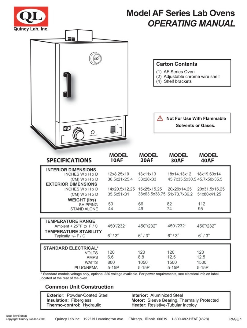
(1) AF Series Oven
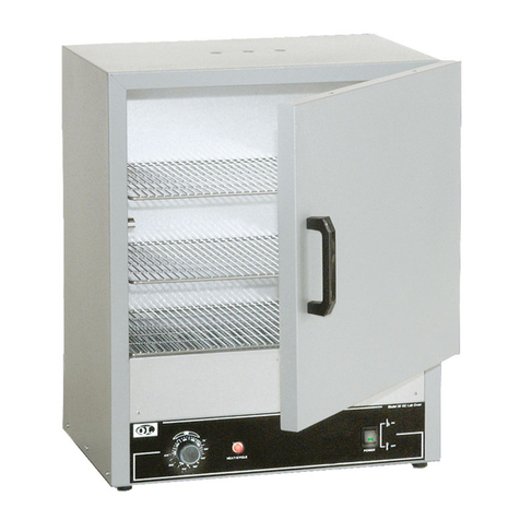
(2) Adjustable nickle-plated wire shelves
(4) Shelf brackets
Approvals:
Underwriter’s UL / CUL, United States
Canadian for laboratory equipment.
Compliance: UL Standard 61010-1
IEC 61010-1.
uincy
ab
Analog Series Air Forced (AF) Lab Oven
Operating Manual
INTERIOR DIMENSIONS
INCHES W x H x D
(CM) W x H x D
EXTERIOR DIMENSIONS
INCHES W x H x D
(CM) W x H x D
WEIGHT (lbs)
SHIPPING
STAND ALONE
50
44
66
49
82
74
112
95
STANDARD ELECTRICAL
TEMPERATURE RANGE
CONTROL STABILITY
Exterior: Powder Coated Steel Interior: Aluminized Steel
Insulation: Fiberglass Motor: Thermally Protected
Thermo-control: Bimetal(10 series) / Hydraulic Heater: Resistive-Tubular Incoloy
Ambient + 25°F to: F / C
NOT FOR USE WITH FLAMMABLE
LIQUIDS OR GASES
Issue Rev 10.22 Quincy Lab Inc. 109 Shore Dr. Burr Ridge, Illinois 60527 1800-482-HEAT (4328)
Copyright Quincy Lab Inc. 2022
PAGE 4 PAGE 1
For models 10AF, 20AF, 30AF, & 40AF
WATTS
VOLTS / AMPS
PLUG / NEMA
SPECIFICATIONS MODEL
10AF (-1)
MODEL
20AF (-1)
MODEL
30AF (-1)
MODEL
40AF (-1)
POWER
Switch
opening
HEAT/CYCLE
ON
OFF
l
Q
12x8.25x10
30.5x21x25.4
13x11x13
33x28x33
18x14.13x12
45.7x35.5x30.5
18x19.63x14
45.7x50x35.5
14x20.5x12.25
35.5x51x31.7
15x25x15
38x63.5x38
20x29x14
51x73.7x35.5
20x31.5x16
51x80x40.7
450° / 232° 450° / 232° 450° / 232° 450° / 232°
6° / 3° 6° / 3° 6° / 3° 6° / 3°
FREQUENCY
(230V) Model VOLTS / AMPS 230 / 3.5 230 / 4.3 230 / 7.0 230 / 7.0
120 / 6.3 120 / 7.9 120 / 12.5 120 / 12.5
( 230V) Model WATTS 800 1000 1600 1600
750 950 1500 1500
50/60 Hz 50/60 Hz 50/60 Hz 50/60 Hz
(230V) Model PLUG / NEMA 6-15P 6-15P 6-15P 6-15P
5-15P 5-15P 5-15P 5-15P
10AF-1, 20AF-1, 30AF-1, & 40AF-1
(-1) indicates 230V model
Typically ± °F / °C
Common Unit Construc�on

Plug the oven into a grounded outlet rated for your unit's labeled voltage. A separate circuit or breaker should be
dedicated for the oven.
Do NOT modify the provide plug. Do NOT use an extension cord.
Position the unit in its ultimate operating location. Maintain a minimum of
4" of airspace around the unit and a minimum of 18" above the unit’s motor
cover. The portholes at the top of the unit will expel a small amount of warm air
through forced convection. (FIG.1)
The unit is ready for your immediate use and no adjustments are necessary. For normal operation and temperature setting
follow the steps below.
1. Turn the power switch to the ON (UP) position by pressing on the rocker switch.
2. Rotate the oven’s dial clockwise to a number setting (10AF series) or temperature setting to start the heating process.
Safety Precautions
Set-Up & Installation
General Operation
FIG. 2
Read Operating Instructions thoroughly prior to operation
Use only a grounded outlet that is rated for your model's electrical requirement.
Do not modify the oven or factory control settings to operate the oven above the stated maximum operating
temperature.
Exterior surfaces of the oven may become hot to the touch when operating at higher set temperatures.
Do not leave the oven unattended during operation.
Do not place volatile or combustible materials inside the oven.
Do not use any flammable solvents or gases or materials that may contain flammable solvents or gases, or with
liquids, vapors or chemicals that produce toxic gases.
Do not use open liquids in the oven.
Conduct periodic maintenance as required.
WARNING
Warns of a possible electrical shock
IMPORTANT
Refers to an important note in the usage of the unit
WARNING
Warns of a possible risk of fire
CAUTION
Cautions of HOT exterior surface during operation
WARNING
Warns of possible injury or muscle strains, use assistance when moving or lifting
Operate the oven in accordance with all state, local, and federal laws that may govern its usage for your specific
application. Observe the following safety precautions:
PAGE 2
Exhaust ports
Upper fan
plenum
Motor cover
Heater
Rear fresh air
intake vents
Install the adjustable shelf by placing the ends of the wire shelf bracket into the
corresponding holes located on the inner sides of the oven at the desired
height. Push the ends of the bracket into the holes until the first bends in the
bracket are against the wall, then rotate the bracket down. Place the shelf on
the brackets. (FIG 2)
The exhaust ports should NOT be used as chamber access for
temperature-measuring probes. Insertion of any such probe or
device may damage or unbalance the circulating fan blade at the
top of the oven chamber.
Do not cover or place anything on the top surface of the motor
cover. This can cause the motor in the oven to severely overheat
risking the possibility of fire.
A
B
C
D
FIG. 1

For 20AF, 30AF, and 40AF models: These models come equipped with a dual-range "quick-set" knob dial. This feature
makes it easier to hit a target temperature range from a cold start, whether using the Fahrenheit or Centigrade scale.Turn
the thermostat knob to the desired temperature indicated on the knob (Fahrenheit), or the dial (Centigrade).
PAGE 3
Chamber Loading
Understanding the unit's thermal convection and "load-effect" are necessary to optimize oven’s performance. Article or
media processing times and/or uniformity are largely dependent on load density and positioning.
Process the smallest possible load the application or workload will permit. For best processing of small multiples or a
single item, adjust one shelf so that the article(s) is centered in the Lab Oven.
Avoid large solid trays or foil on lower shelves, this can drastically limit heat to shelves and articles placed above. (FIG. 4)
Important guidelines for chamber loading and processing:
Load the oven so that heated air circulation within the chamber is not impaired.
Avoid extremely large (in quantity or size), or high-density loads ( FIG. 5 ).This will show by non-uniform processing and
long or impossible "heat-through" times. To help determine a large load's suitability, use the set-point recovery time (the
time it takes for the temperature to recover to the original set temperature once the load is placed), as a guide.
Leave a space between articles on the shelf as shown in (FIG. 3).
To reduce recovery time after inserting a load, reduce the load proportionally. Also, large loads may require an elevated
set temperature for the solution to reach and maintain a lower target temperature.
General Operation (continued)
For 10AF models: Rotate the dial clockwise to around the number '8'. The “heat/cycle” light will come on indicating
heater activity. Monitor the reading on the door thermometer until it reaches the desired temperature. Once the
desired temperature is reached, rotate the control knob very slowly counter-clockwise until the heat-cycle light turns off.
The thermostat will then cycle automatically maintaining the set temperature.
Rotate the dial to the desired temperature. The heat-cycle light will illuminate until the set temperature is reached. Once
reached, the heat-cycle light will cycle on and off with the heaters maintaining set temperature. Typically, the oven will
need to cycle at a set temperature for a minimum of 20 minutes before it will achieve equilibrium and become stable.
The temperatures printed on the "quick-set" dial are designed to help quickly set a temperature to within close
proximity of the indicated dial temperature. Small rotational adjustments to the dial will likely be required to set a
more precise temperature setting as measured against the reading from the door thermometer (supplied), or
another measuring device.
Any degree of offset observed for a given temperature setting may be different for other temperature settings on
the dial. The control dial is calibrated at the factory in the middle of the model's temperature range and is
therefore most accurate in these middle-range temperatures. Over time, continuous use at a single temperature
setting may require periodic re-adjustment as the contacts wear or as ambient temperatures change seasonally,
or from air conditioning or heating. See also: "Temperature Range Adjustment insert for more information".
Avoid placing articles or media against or within an inch of the walls, especially on the lower shelf. Heated air from the
lower heat shield, is designed to travel up the sidewalls and can have a slightly elevated temperature from the setpoint
and the rest of the chamber.
FIG. 3 FIG. 4 FIG. 5
Ideal Air
Circulation
Obstructed
Air Circulation High Density
load
To set a temperature in degrees Centigrade, turn the knob in a clockwise direction until the white triangle with the "°C"
marking is pointing toward the desired temperature printed on the face of the control panel.
To set a temperature in degrees Fahrenheit, turn the knob in a clockwise direction until the desired number on the knob is
directly under the white triangle with the "°F" marking.

Oven Safety Reset- To protect the oven’s electrical components and for the safety
of the user, if the unit exceeds its maximum temperature, an internal safety “snap disc”
will cut power OFF to the oven until it is manually reset (FIG.6).
To Reset - disconnect the oven from power. Next, lay the oven on its back and
remove the bottom cover. Locate the round “snap disc” and push on the button to reset.
Maintenance / Cleaning Procedures / Common Replacement Parts
The AF Lab Series Ovens are designed to be virtually maintenance free, but operational safety requires periodic
cleaning and chamber temperature accuracy verification (see temperature range adjustment insert for more information).
Cleaning Procedure - Periodically check the rear air intake vents for dirt or dust build-up. Keep the intake &
exit ports clear of obstruction and clean of dust and dirt. To reduce the risk of fire, it may be necessary to remove the
bottom plate cover to clean or vacuum any dirt and dust build-up. To clean the exterior and interior surfaces, use a
damp cloth or an all-purpose cleaner. Avoid commercially available oven cleaners.
PAGE 4
Quincy Lab, Inc. warrants to the original purchaser that this product will be free from defects in material and
workmanship under normal use throughout the warranty period. The standard warranty period for this instru-
ment is twenty four (24) months from date of shipment. The instrument warranty is supplemented with a three
year warranty on the heating element. Please refer to your invoice or shipping documents to determine the active
warranty period. This warranty covers parts & labor (labor at factory only) and shipping cost for replacement parts.
Limited Warranty
Technical Support
Email:
Voice:
Fax:
800-482-4328 ; Press 2 for tech support.
773-622-2282
Quincy Lab, Inc.
109 Shore Dr.,
Burr Ridge, Illinois 60527
If you have any ques�ons or need technical assistance, contact Quincy Lab technical support.
Visit us on the web at www.quincylab.com
Thermal Safety Reset (Snap Disc)
Thermostat Rocker Switch
PART # 101-2223 PART # 201-2213
Motor
Reset button
Thermo Fuse (Snap Disc)
Common Replacement Parts
For a full list of
replacement
parts scan QR code.
The oven’s chamber temperature stability can be affected by changes in ambient (room) temperature and/or equipment
running in close proximity (creating microclimates) or cycling on the same electrical circuit. Take time to see how unit
location or changes in room temperature from seasonal heating or air conditioning may influence the oven’s set
temperature. For best chamber temperature stability, keep the ambient temperature stable.
Unit not turning ON
when power switch
is in the ON position
Troubleshooting
1. Check if the unit tripped a GFCI outlet or fuse. Try a non GFCI
power outlet connection before moving to number 2 on this list.
Oven has power but
its not heating
or is overheating.
1. Tripped GFCI power outlet
3. Disconnected / loose wires.
PROBLEM POSSIBLE CAUSE WHAT TO DO BEFORE CALLING TECH. SUPPORT
2. If the oven does not heat, overheats, or does not maitain a
setpoint temperature, it’s an indication of a bad/broken/old
thermostat. Replace thermostat on the unit.
1. Thermal Fuse (10AF models only)
Hydraulic Thermostat 115 Volt Switch
2. Thermal safety disc tripped. 2. Reset the oven’s “snap disc”. Refer to “Thermal Safety
Reset’ section above for more information.
Chamber Loading
(Continued)
PART # 201-2217
Bimetal Thermostat (Model 10)
PART # 301-2235
115 Volt Motor
PART # 301-2230
230 Volt Motor
3. Check all wire connections in the electrical area (bottom) and
make sure there are no loose or disconnected wires in the unit.
2. Bad / broken / old Thermostat
1. Check thermal fuse in the back of the thermostat is not blown
or broken. Repacle if blown/broken.
PART # 201-2213-1
230 Volt Switch
FIG. 6

STEP 1
LAB OVEN SERIES
Calibra�on and Temperature Range Adjustement for Analog Lab Ovens
A calibration to the knob can be performed if the chamber temperature is off by 15 degrees Fahrenheit or more from the
temperature number printed on the dial on models 20,30,and 40 GC/AF.
A temperature range adjustment can be performed to the oven when not able to reach lower or higher temperatures when
set with the dial.
REMOVE COMPRESSION PIN
TO ACCESS TRIM-SCREW.
Understanding the Knob
For 10GC/AF model ovens, the numbers on the dial represent a
power setting of 1 through 10. For all other models, the numbers
represent a temperature in degrees °F (Fahrenheit) on the dial and °C
(Celsius) on the back panel. (Fig A)
The numbers printed on the unit’s dial are only to be used as a
reference and do not represent an actual temperature inside the
unit. Use the thermometer provided with the unit to obtain a true
temperature from inside the oven.
OFF
450
400
350
300
150
200
250
°C
0
9
8
7
6
5
4
3
2
1
Make sure the screw recessed in the shaft has moved after
adjustment.
Allow the temperature to settle before making any subsequent
adjustments.
IMPORTANT
10GC & AF
Oven Dial GC & AF
Oven Dial
OFF
450
400
350
300
150
200
250
°C
FIG. A
FIG. B
FIG. C
Calibrating the dial
Set the dial to the most frequently used temperature and allow the oven
to achieve temperature stability. (FIG. B)
Using a 5/64” Allen Key, loosen the knob screw(s) and remove the
knob from the oven. For models 20,30, and 40 remove the compres-
sion pin from the thermostat shaft as shown in (FIG. C).
Using a small blade screwdriver, adjust the trim screw in the shaft
center to adjust the oven’s temperature.
Make slight 1/8th turn adjustments at a time. Allow the oven’s
temperature to be stable before placing the knob.
Follow the steps below to calibrate the oven’s dial (printed) tempera-
ture to the temperature reading from inside the oven’s chamber as
measured by a known accurate device (models 20, 30, and 40 only).
b) Turn the trim screw
clockwise to adjust
the temperature DOWN.
a) Turn the trim screw
counter-clockwise to
adjust the temperature UP.
(-)
(+)
°F
Email:
Voice:
800-482-4328 Opt 2
Technical Support
STEP 2
STEP 3
To adjust the temperature range, rotate the dial to the lowest or highest
setting allowed by the dial before removing the knob.
Insert
Do not modify the oven to operate above the stated maximum operating temperature when adjusting the oven’s temperature range.
Calibrate the dial at the most frequently used temperature using the oven’s thermometer or measuring device known to be accurate.
This manual suits for next models
8
Table of contents
Other Quincy lab Laboratory Equipment manuals