Idmed Algiscan User manual
Service Manual NeuroLight / AlgiScan
Last Update 2021/04/15
Ref: NL/ALG-SM-RevB-EN
SERVICE MANUAL

Service Manual NeuroLight / AlgiScan - Rev B 2

Service Manual NeuroLight / AlgiScan - Rev B 3
CONTENTS
I. Maintenance Operations............................................................................... 4
Shared maintenance operations between AlgiScan/NeuroLight.. 4
a. Camera control .......................................................................................................................... 4
b. Hardware part control............................................................................................................. 4
c. Software part control............................................................................................................... 4
d. Functionals controls ................................................................................................................. 5
Maintenance operations specic to the AlgiScan................................ 6
a. Hardware part control............................................................................................................. 6
b. Functionals controls ................................................................................................................. 6
II. Disassembling process................................................................................. 8
a. Disassembling the housing.................................................................................................. 8
c. Battery change...........................................................................................................................10
d. Disassembling optical room...............................................................................................10
e. Disassembling mother board (for screen change)............................................... 11
f. Wireless charging coil change ............................................................................................ 11
g. Disassembly of the push/pull LEMO connector......................................................... 11
h. Mounting sensor cable push/pull connector............................................................. 11
Mechanical Drawing.....................................................................................................................13
Service Manual NeuroLight / AlgiScan - Rev B 4
Actions described in this service manual must be carried out by a technician approved by
IDMED. Refer to the user manual for information on cleaning and disinfection, end-of-life
material / recycling, and the environment.
I. Maintenance Operations
Shared maintenance operations between AlgiScan/NeuroLight
a. Camera control
- Check the cleanliness of the main objective
- Check the alignment
- Check the cleanliness of the diffusing panel,
- Check the image sharpness (focus)
- Check the intensity of the white LEDs (ash) with the luxmeter. If it is necessary to adjust the
intensity of the white LEDs, the “Flash intensity test” procedure must be used.
- Check the pupil calibration (see sheet nal test ENR/13/20-D with barcode)
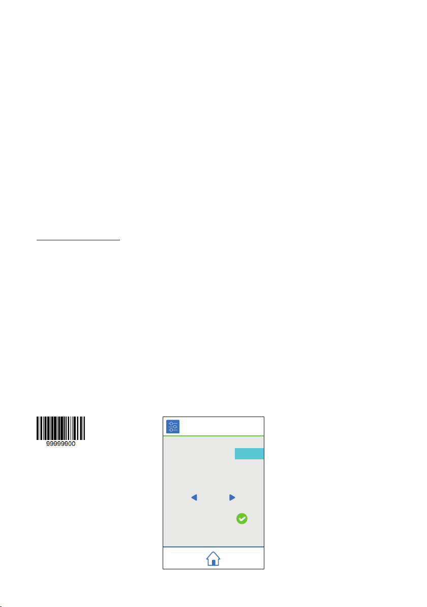
Necessary accessories:
- The luxmeter (ref.: LM100 - AMPROBE)
- The «Pupil Target» card
- The rigid eyecup specic for test
b. Hardware part control
- Check that the battery is working properly. The battery should be changed every 2 years. (see
Disassembly section).
- Check the appearance of the front and rear silicone bumpers
- Check the condition of the labels
- Check for cleanliness / clean the glass in front of the scanner
c. Software part control
- Empty the patient directories
Caution: This action must only be carried out with the written permission of the customer.
To do this, scan the barcode here below (or the barcode of the sheet nal test ENR/13/20-D) and
press the green button “Formatting SD card”.
Flash intensity
Threshold brightness camera
Set size pupille
Formatting SD card
480
100
1000
Extra settings
Service Manual NeuroLight / AlgiScan - Rev B 5
- Check the time
- Check the date and language
d. Functionals controls
- Check the touch screen by navigating the user interface.
- Scan a barcode to check that the reader is working properly.
- Perform a full charge cycle.
1) Necessary material
- AlgiScan or NeuroLight to test
- 1 «Pupil Target» card
- The rigid eyecup specic for test
- 1 luxmeter
- The sheet nal test ENR/13/20-D
Rigid eyecup «Pupil Target» card
2) Pupil size test
- Put the rigid eyecup on the camera
- Aim the camera at the black dot on the pupil target card by placing the eyecup on it
- Check the size that appears on the screen. The pupil size should be 3 mm (with an accuracy of
+/- 0.1mm), otherwise continue with the following steps.
- Scan the barcode
- Increase or decrease the “Pupil size calibration” coefcient until 3 mm is reached.
- Repeat the tests
- Transfer this coefcient to the test sheet ENR/13/20-D.
3) Testing the ash intensity
- Put the rigid eyecup on the device
- Turn on the light meter
- Scan the barcode to enter the “Additional Settings” menu. This will turn on the LEDs continuously.
- Position the eyecup on the light meter.
- Adjust the “Flash Intensity” coefcient until you get between 320 and 330 Lux.
- Record this coefcient on the ENR/13/20-D test sheet.
Service Manual NeuroLight / AlgiScan - Rev B 6
Maintenance operations specic to the AlgiScan
a. Hardware part control
- Check the condition of the LEMO connector (see LEMO connector change section)
b. Functionals controls
- Check the 60mA pulses generated by the AlgiScan using the 4K test impedance (see detail here
after)
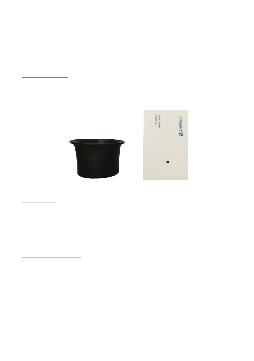
Necessary accessories:
- An oscilloscope
- An impedance 4K pulse test (IMPtest)
- The sheet nal test ENR/13/20-D
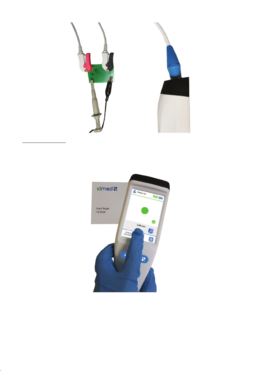
Detail regarding the control of 60mA pulses generated by AlgiScan:
1) Necessary material
- AlgiScan to test
- 1 CAB-STIM3
- 1 oscilloscope + probe
- 1 impedance 4K test card
- 1 «Pupil Target» card
- The rigid eyecup specic for test
Rigid eyecup «Pupil Target» card
Impedance 4K
test card
2) Oscilloscope setting
- 50μs/Div
- 1V/Div
Note: Here, 1V/Div corresponds to 10mA/Div. The expected result is between 5.4V and 6.6V, i.e.
between 54mA and 66mA.
3) Wiring
- Connect the probe to channel 1 of the oscilloscope.
- Connect the end of the probe to the impedance card on the small + pin and the clamp on the small
pin.
- Connect the clamps of the CAB-STIM3 to the impedance card, red on + and black on -.
- Connect the CAB-STIM3 to the AlgiScan
Service Manual NeuroLight / AlgiScan - Rev B 7
4) Perform the tests
- Put the rigid eyecup on the AlgiScan
- Set the AlgiScan to PPI mode
- Aim at the black dot on the “Pupil Target” card with the AlgiScan by placing the rigid eyecup on it.
- Launch a PPI by pressing and holding the central icon for several seconds until all the “beeps”
sound.
- At each audible “beep”, the intensity of the signal must increase on the curve displayed by the
oscilloscope until it reaches the maximum expected intensity (between 54mA and 66mA).

Service Manual NeuroLight / AlgiScan - Rev B 8
- The intensity must correspond to that displayed on the AlgiScan display.
Record the result on the sheet nal test ENR/13/20-D.
II. Disassembling process
a. Disassembling the housing
1) For the AlgiScan only, unscrew the LEMO connector located on the bottom silicone bumper.
2) For all devices, with a plastic stylus, remove the product name sticker (‘AlgiScan’ or ‘NeuroLight’) to
uncover the screws and then proceed with the front and rear bumpers as well as the silicone eyecup.

Service Manual NeuroLight / AlgiScan - Rev B 9
Silicone bumper
Silicone bumper Product name sticker
3) Unscrew the 6 screws on the front panel using a phillips screwdriver.
4) Disassemble the 2 parts of the handle.
5) Remove the K6 jumpers and disconnect the K2 battery.
b. LEMO connector change (only for the AlgiScan)
1) Unsolder the 2 wires in K1 and then resolder the LEMO connector supplied.
2) Then solder the n°1 wire on the plus, the n°2 wire on the minus.
3) To reassemble the unit follow the previous steps in reverse order.
Note: Both silicone bumpers must be glued with silicone adhesive.

Service Manual NeuroLight / AlgiScan - Rev B 10
c. Battery change
1) Unscew the battery holder.
2) Replace the battery by putting the wires down while sliding them up.
3) Reposition the battery holder, being careful not to overtighten the screws.
4) Reconnect the battery and the jump and reassemble the unit.
d. Disassembling optical room
1) Unscrew the 6 screws on the optical room using a phillips screwdriver.
2) Disconnect connector K1
3) Remove the optical room
4) Clean the diffusing panel with a dusting spray
Diffusing panel

Service Manual NeuroLight / AlgiScan - Rev B 11
e. Disassembling mother board (for screen change)
1) Carefully remove the glue from the wireless charging coil
2) Unscrew the 4 screws that hold the motherboard.
3) Disconnect the connection ribbon of the screen and touch pad (x4 and x5)
4) Remove the screen with relatively strong pressure (Caution: wear safety gloves)
5) Remove the seal and replace it
6) Connect the new display to the motherboard
7) Place the screen previously connected to the motherboard on the seal after removing the lm
from the it.
8) Replace the motherboard and put the screws back in place.
f. Wireless charging coil change
1) Same as section 1) disassembling mother board
2) Same as section 2) disassembling mother board
3) Unsolder the coil
4) Solder the new
5) Screw the motherboard back on
6) Place the coil in its slot
7) Apply 3 points of hot glue to x it
g. Disassembly of the push/pull LEMO connector
Remove the blue cable bend relief then slide it on the cable.
Cut the cable as close as possible from the connector.
To re-do the connector please see the instruction below “Mounting sensor cable push/pull
connector”.
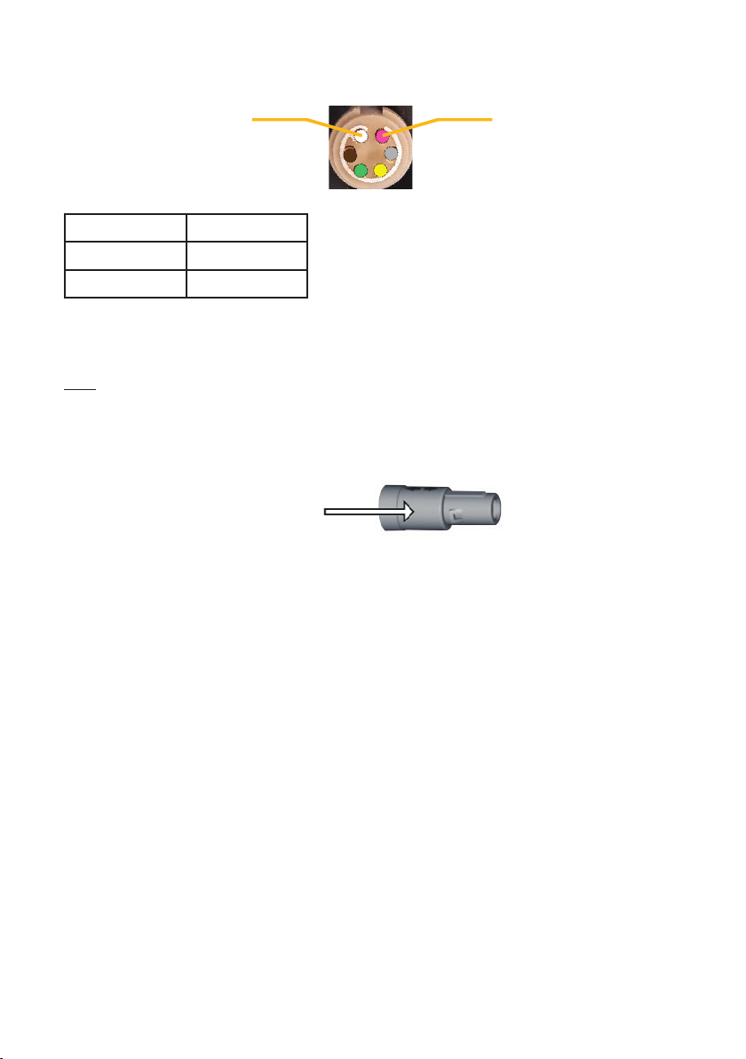
h. Mounting sensor cable push/pull connector
Connector mounted with its blue cable bend relief
In order to mount the push pull connector, rst insert the blue cable bend relief, then mount and sold
the parts in the following order:
Backnut Cable collet Insulator +
contacts
Shell
1 2 3 4
Remove the sheath between 1cm and 1.4cm (1/2inch).
Cut all wires and shielding except the white and brown wires.
Strip these two wires about 3mm.
Tin all wires.
Service Manual NeuroLight / AlgiScan - Rev B 12
The 2 leads have to be soldered to match the following pins conguration:
Pin 1 Pin 6
Pins conguration
Connector pins Cable Leads
1 White
2 Brown
Solder rst the white cable.
Solder all cables counter-clockwise.
Test the proper functioning of the connector using a patient simulator.
Note: If the results are not satisfying please check the soldering.
Apply a drop of glue on the cable collet, then insert the backnut inside the cable collet.
Screw the connector at the max and swipe out the excess of glue.
Apply a drop of silicon glue on the shell of the LEMO connector to keep the blue bend relief in place
(ex.Silcoset 153).
Apply here
Let dry for 24 hours.
Service Manual NeuroLight / AlgiScan - Rev B 13
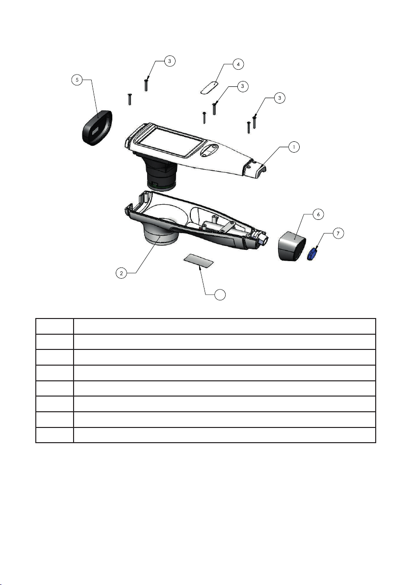
Mechanical Drawing
Overall set AlgiScan and NeuroLight
8
1 Front housing
2 Back housing
32,5x1.6mm countersunk screw
4Product name sticker
5 Front silicone bumper
6 Rear silicone bumper
7 LEMO connector (AlgiScan only)
8Identication label

Service Manual NeuroLight / AlgiScan - Rev B 14
Front sub-set
1 Front housing
2 Screen seal
3 Touch screen
4 barcode reader
52,5mm x 10mm screw

Service Manual NeuroLight / AlgiScan - Rev B 15

Copyright 2021 - IDMED SAS. All rights reserved. No information or part of this document may be reproduced or transmitted in any form or by any means, without the prior written permission of IDMED.
Other manuals for Algiscan
1
This manual suits for next models
1
Table of contents
Other Idmed Medical Equipment manuals


