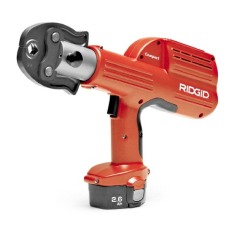
RIDGID RP318 User manual

E M E R S O N . C O N S I D E R I T S O L V E D .
™
© 2020 RIDGID, Inc.
RP318
•English – 15
•– 01

...............................................................................................................................................................2
......................................................................................................................................................................3
工作区域安全..................................................................................................................................................................3
电气安全.........................................................................................................................................................................3
个人安全.........................................................................................................................................................................4
电动工具的使用和维护................................................................................................................................................... 4
电池工具的使用和维护................................................................................................................................................... 4
服务................................................................................................................................................................................4
压接工具安全..................................................................................................................................................................5
概述................................................................................................................................................................................5
规格................................................................................................................................................................................5
标准设备.........................................................................................................................................................................6
...................................................................................................................................................................6
....................................................................................................................................................7
压接前的准备工作...........................................................................................................................................................8
使用典型的剪式压接钳对管件进行压接..........................................................................................................................8
使用典型的转换压接钳和压接环组件进行管件压接........................................................................................................9
检查压接情况................................................................................................................................................................10
清洁和润滑....................................................................................................................................................................10
需要RIDGID授权维修中心提供的维修服务...................................................................................................................10
...................................................................................................................................................................................10
...................................................................................................................................................................................10
........................................................................................................................................................................11
............................................................................................................................................................................11
............................................................................................................................................................................12
RP318 ................................................................................................................................................................13
............................................................................................................................................................................14
在下方记下序列号并妥善保管铭牌上的产品序列号。
RP318
RP318
序列号
12
RP318 压接工具

34
•
如果在使用当中稍不留神,就会导
致比较严重的伤害事故的发生。
•个人防护用
品包括防尘面罩、防滑安全保护鞋、安全帽或听力防
护装置。适当使用这些防护用品,将减少人身伤害事
故的发生。
•
当你携带
电动工具,手指不小心触动开关或在开关置于开机状
态时接通电动工具都会导致安全事故的发生。
•如果这
些工具处在旋转部件上,将会导致人身伤害。
•
这样会使你在意外情况下更好的控制工具。
•
宽松的衣服、首饰和
长发容易卷入活动部件中。
•
从而减少与粉尘相关的事故。
•
合适的工具将会使你更快、更安全地完成作
业。
•任何
电动工具如果不能控制开关,都是非常危险的并
且必须立即进行修理。
•
这些措施可以预防意
外接通工具的风险。
•
因为电动工具对于未经过培训的人员来说是
非常危险的。
•
许多事故的发生都是由于工具
的维护不当造成的。
•这样工作时不易粘结,易于
控制。
•
如果工具与工作环境
和目的不匹配,可能会导致危险的发生。
•适
合某一特定类型电池的充电器如果用于其它类型的电
池充电可能会引发火灾。
•使用任何其它类型电池
可能导致人身伤害或火灾。
•
同时将电池两极短路可能导致灼伤或起火。
•
从电池中溢出的液体可能导致刺激
或灼伤。
•
这样可以确保工具的使
用安全和保养正确。
电动工具的涵义是指带有电源线直接由外部电源提供电力和不
带电源线由电池提供电力的两类设备。
•混乱和昏暗的环
境容易引起安全事故的发生。
•
电动工具易产生火
花,会引燃这些粉尘或气体。
•
注意力分散容易导致安
全事故的发生。
在本操作手册和该产品上,利用了一些安全标识符号和专业词汇来表达重要的安全注意事项和安全规范。
本节内容主要是帮助读者能更好地理解这些标识符号和用语。
这是安全警告符号-用于对一些潜在的人身伤害危险进行警示。
必须遵守安全信息的指导来规避可能的伤害事故发生,甚至死亡。
危险警告符号-表示一些存在危险情况的环境,如果不能避免,将导致死亡和严重的伤害事故。
•
不改变插头并与插座相匹配将会降低电击事故的发
生率。
•
如果身体和接地物体接触将增加
触电事故的发生率。
•水进入电动
工具将增加触电事故的发生率。
•
电源线损
坏或卷入其它物体中都会增加电击事故的发生率。
•
这样能降低电击事故的发生率。
•
GFCI 使用GFCI可以降低电击事
故的发生率。
警告符号-表示危险的境况,如果不能避免,也可能导致死亡或严重的伤害事故。
小心符号-表示危险的境况,如果不能避免,可能导致轻微或中等程度伤害事故。
注意符号-表示和保护财产相关的安全信息。
该符号意味着使用者在使用该工具前必须仔细阅读操作手册,因为操作手册里介绍了重要的安全注意事项和正确的使用方法。
该符号表示操作或使用工具时必须始终佩戴带侧面安全防护罩的安全眼镜或护目镜以降低眼部受伤的风险。
该符号表示手、手指或身体其他部位有被压伤的风险。
这是电击风险的符号。
NOTICE
DANGER
WARNING
CAUTION
RP318 压接工具
RP318 压接工具

产品概述、规格和标准设备
概述
RP318压接工具和相应的标准压接钳配合使用,通过机
械力施加于管件上形成不透水的永久密封。当按下RP318
的开关后,一个内置的电机会驱动液体进入工具的油缸,
让凸轮向前运动并产生数千磅的压力施加于特殊设计的
管件上。附件也可供其它用途使用。
整个压接过程大约持续7秒。当开始压接管件时,松开
扳机,工具会立即停止,再次按下扳机,工具会自动继
续工作直到完成整个过程。工具尾部的LED显示了不同
的故障类型,如温度不正确、电池电量低或者需要维护
保养等。
RP318带有两(2)个织物环,可用于装配肩带或扎绳。
其它安全须知
本节内容是专门针对该电动工具的一些重要安全注意事项。
在使用RP318压接工具前认真阅读此内容,可以减少电击危
险或严重人身伤害事故的发生。
请注意保存好这些安全指导内容!
RP318便携式手提箱的夹层内有一份此操作手册,用于指导
操作者正确使用该工具。
压接工具安全使用规范
•请使用RP318压接工具的RIDGID®型压接附件(如压
接钳、压接环、转换压接钳等)。
将RP318压接工具用于其它用途可能损坏本工具和附
件,甚至导致人身伤害。
•压接过程中,请确保手指和手远离压接附件。否则压
接钳或部件可能压伤手指和手,甚至导致骨折和切断。
•永远不要试图维修损坏的压接钳、压接环、转换压接
钳或其它部件。如果对这些附件进行焊接、打磨、钻
孔或其它改变,在压接时会引起严重安全事故。报废
损坏的压接钳,需要用新的进行更换。除了损坏的压
接钳复位弹簧,切勿更换其他零件。详情请致电艾默
生精密工具技术(上海)有限公司技术服务部门。
•工具使用时将产生的力量巨大,可能打破零件造成伤
害。使用过程中,请勿倚靠,并佩戴适当的保护装置,
包括保护眼睛。
•要确定所要压接的管件制造商,并使用对应的RIDGID
压接工具及钳口。使用不正确的设备和方法可以导致
压接不到位,损坏设备。要避免引起严重的人身伤害
或死亡。
警告
5 6
图1 - RP318压接工具和标准型压接钳组
电压..........................................18V DC
安培数......................................18 A
功率.........................................324 W
重量..........................................2.9 公斤 (仅工具-无电池)
凸轮压力...................................32kN
规格
RP318电动压接工具:
电机
范围..........................................15° F到122° F (-10° C到50° C)
工作周期...................................每分钟3次压接
工作温度
•在使用RIDGID工具前,请阅读并理解以下内容:
–操作手册
–电池/充电器使用手册
–其它与本工具一起使用的设备说明
–RPA 120/220 AC电源适配器使用手册
–请联系艾默生精密工具技术(上海)有限公司
–客户服务:400-820-5695
–网址:www.RIDGID.cn
未能遵守所有的说明和警告可能导致财产损失和/或
严重伤害。
如果对RIDGID®产品有任何疑问:
标准设备
RP318如与电池一同订购,则提供的是2.5Ah的电池,
5.0Ah电池可作为附件提供(见第10页)。更高安培数
的电池每次充电可进行更多次的压接,但重量更重。
注意!里奇提供两种系列的压接钳和附件:
•标准系列
•紧凑型系列
这两个系列不能互换,即标准系列压接钳仅适用
于标准系列的压接工具,如( RP340,RP318,
CT-400)。同样,紧凑型系列压接钳仅适用于紧
凑型系列的压接工具,如(紧凑型100-B,RP 200-B,
RP 210-B)。
管道材料的选择和接头的形式有该系统的设
计人员和/或安装人员来负责。在安装前,应仔细权衡管
道的使用环境,包括化学因素和温度条件。请咨询管道
压接系统供应商来获得相关的选择信息。
工具完好性检查
在每天使用压接工具前,请仔细检查工具和校正发现的
问题,以减少电击、机械损伤、附件失效和其它原因引
起的各种伤害事故发生的风险,并保护工具免受损坏。
1. 确保检查工具前已取下电池。检查电池是否完好。如
果发现有任何不妥的地方,不要继续使用工具并立即
进行修理。
2. 清除任何油脂、灰尘,尤其是手柄和控制元件上面。
这样可以防止使用过程中工具发生滑脱。
3. 按照下列事项检查工具:
- 装配适当,正确维护, 产品完整。
- 是否有任何破损,磨损,丢失,或结合部分错位。
- 确保附件安装销可以顺利全开和全闭(图3和4)。
- 确认开关自如,不卡或粘连。
警告
- 警告标签存在和可读(图2)。
- 检查织物的循环是完好无损的,缝合不破。
- 任何其他影响安全和正常运行的情况。
- 如果发现有任何问题,不要使用压接工具直到问
题被修复。
4. 按照操作手册要求检查和保养工具、各种附件、电
池及充电器。
5. 保持操作时手掌干燥,装入充满电的电池。按一下红
色按钮,打开压接工具。LED灯会亮起并一直亮着表
示工具处于就绪状态。如果有其它情况,请根据故障
诊断代码(第10页)来确定下一步行动,在工具恢复
正常前不要使用。让手指和手远离凸轮,测试机器是
否可以正确操作。当使用附件时,如果负载足够大,
工具将会自锁以确保一个完整的压接过程能够完成。
6. 操作检查完毕后,用干燥的手取下电池。
注意
图2压接工具警告标签
剪式压接钳 组
压接钳
电池 工具外壳
开关
手柄
压接钳侧板
织物环
LCD屏幕
LED灯
泄压按钮
已压接次数
故障提醒
图2-LCD屏幕
电池电量温度报警
连接安装销
RP318 压接工具
RP318 压接工具
标签

7 8
工具组装和工作区域检查
参照以下程序来组装工具和清理工作现场,可以减少电击、火
灾、机械损伤或其他原因引起的伤害事故的发生,同时保护工
具和管道系统完好。
1. 从以下几个方面检查工作区域:
•照明充分
•可燃液体、气体或粉尘容易引起燃烧。请不要在这
些环境下使用工具,直到确认并进行整改。压接工
具没有防爆保护措施,因此会产生火花。
•在清洁、干燥、稳定的环境下操作。不要站在水中
使用工具。
2. 检查所要进行的工作,根据应用场合来选择合适的
里奇工具及附件。如果附件使用错误,也会引起伤
害事故和工具损坏及管道连接不符合密封要求的情
况。如需完整的里奇电动压接工具附件清单,请访问
www.RIDGID.cn网站查询产品目录或致电艾默生精
密工具技术(上海)有限公司技术服务热线400-820
-5695咨询。确保已根据工具和附件的使用说明来对
其进行检查。
3. 权衡工作区域看是否需要进行隔离,使旁观者远离工
作地点,因为旁观者会使操作者注意力分散。
4. 确保已取下电池,然后解锁并完全打开附件安装销
(见图3和图4)。如果工具中已有附件,则将其取下。
5. 装入正确的附件,然后完全闭合附件安装销,并旋转
到锁定位置,如图3。附件安装销必须完全闭合并锁
紧,以防止工具在使用过程中被损坏。
警告
图4完全打开/解锁的安装销
操作指南
始终佩戴安全防护镜来保护眼睛免受粉尘或其它异物的伤害。
在压接循环过程中,保持手指和手远离附件。否则手指和手可
能被工具或附件、工件和其它物件压伤甚至导致骨折或切断。
按照操作指南进行操作,减少受伤和工具被损坏的风险。
以下操作指南部分适用于几种类型的压接工
具附件的使用。严格遵守关于压接工具附件的特别使用
规范和管件生产厂家的安装指导规范。否则,会使管道
安装不正确而产生泄漏,从而导致财产损失。
警告
注意
安全销弹簧
图3完全闭合/锁紧的安装销
图6将剪式压接钳扣住管件
图7 RP318压接工具与管道垂直
6. 确保压接钳和工具与管道垂直(图7),如果压接钳
和工具未与管道垂直,则在压接过程中工具会自己尝
试对齐。这样就会导致压接不当或工具损坏。
7. 按下并松开开关,让工具接通。工具前部的LED灯会
一直点亮,表明工具随时可用。
注意! 如果150秒钟不对工具进行操作,它将自动关闭。
要打开工具,需要再次按下开关。
按下工具的扳机(图1)。让手和手指远离压接钳,以
避免被压伤。压接循环大约为7秒。一旦一次压接循环
开始,且滚轴碰到压接钳臂时,工具会锁定并自动完成
压接循环。当开始压接管件时,松开扳机,工具会立即
停止,再次按下扳机,工具会自动继续工作直到完成整
个过程。这样能确保压接管件的一致性、完整性和可重
复性。
压接前的准备工作
1. 确保工作区域没有闲杂人员和分散注意力的因素影
响,且工具正确组装,工作场所符合工作要求。
2. 按照管件生产厂家的要求进行管道连接。
使用典型的剪式压接钳对管件进行压接
1. 确保RP318安装了正确的压接钳,且安装销完全
闭合且锁紧。
(见“工具组装和工作区域检查”章节)
2. 将充满电的电池装入手柄中。
3. 按下压接钳臂以打开压接钳(图5)。
4. 将打开的压接钳卡在管件周围(图6)。确保按照管
件厂商的使用手册,将压接钳完全对准管件。不要
让工具和压接钳直接悬挂在管件上,以避免工具不
慎跌落造成不必要的伤害或死亡事故。
5. 确保遵循相应管件系统说明中的要求(即管道插入
管件的深度符合要求)。
图5打开剪式压接钳
90°
RP318 压接工具
RP318 压接工具

9 10
如果电池电量太低而不能完成一个压接循环
操作,则RP318压接工具会自动关机。此时,LED灯
不断闪烁进行提示。重新装上充满电的电池重复以上的
操作过程。
如果压接过程中电池没电或工具发生故障,此时要使滚
轴复位或从管道上取下工具,就必须按下泄压按钮(图1)。
如果发生此类情况,则需要对连接处再进行一次压接以
确保压接完整。
8. 压接循环完成后,按下压接钳臂打开压接钳。
9. 从管道上取下RP318和压接钳,检查压接情况。
小心压接过程中可能产生的锋利边角。
使用典型的转换压接钳和压接环组件进行管件压接
1. 确保RP318压接工具安装了正确的转换压接钳,且
安装销完全关闭并锁紧。
2. 将充满电的电池插入RP318后部。
3. 确保管道插入管件的深度正确,即符合管件系统操作
手册中的要求。
4. 打开压接环并将其以正确的角度放在管件上(图8)。
将压接环与管件按照管件系统操作手册中的要求进行
对齐。在压接前,再次检查管道插入管件的深度。
5. 按下转换压接钳臂打开转换压接钳组件。将转换压
接钳两端卡入压接环的转换压接钳口中(图9)。确
保转换压接钳两端完全卡入转换压接钳口中。不要让
工具和转换压接钳悬挂在管件上,以避免工具意外掉
落而引起伤害或死亡。
6. 按下并松开开关,让工具接通。工具前部的LED灯会
一直点亮,表明工具随时可用。
注意!如果150秒钟不对工具进行操作,它将自动关闭。
要打开工具,需要再次按下开关。
按下工具的开关。让手和手指远离转换压接钳,以避免
被压伤。压接循环大约为七(7)秒。一旦一次压接循环
开始,且滚轴碰到转换压接钳臂时,工具会锁定并自动
完成压接循环。当开始压接管件时,松开扳机,工具会
立即停止,再次按下扳机,工具会自动继续工作直到完
成整个过程。这样能确保压接管件的一致性、完整性和
可重复性。
如果电池电量太低而不能完成一个压接循环
操作,则RP318压接工具会自动关机。此时,LED灯
不断闪烁进行提示。重新装上充满电的电池重复以上的
操作过程。
注意
注意
图8将转换压接环安装到管件上
图9将转换压接环连接到压接环上
3. 每次使用后检查附件中的复位弹簧。附件应只需手指
稍许用力就能自由打开和关闭。
需要里奇授权维修中心提供的维修服务
在30000次工作循环后,只要工具开机, LED灯就会闪
烁,这表明需要进行维护保养和校正机器。LED灯闪烁
后,如果不进行维护保养还继续工作循环2000次(共
32000次),工具将自动停机。
维护保养服务为有偿付费项目。
附件
仅下所列附件可与RP318压接工具一同使用。对于应配合其
它相应工具使用的其它附件,如果用于本机器则会导致机器
损坏。为了防止意外发生,请使用为RP318专门设计的附件
或推荐使用的附件。具体见下表。
艾默生精密工具技术(上海)有限公司提供标准型压接附件
来配合标准型压接工具一同使用。请按照管件系统来选择合
适的压接附件。如果要得到完整的压接附件目录,请访问
www.RIDGID.cn网站或致电艾默生精密工具技术(上海)
有限公司技术服务热线400-820-5695。
存放
将电池从工具上取下,并将其与工具一起存放在手提箱
内。不要存放在过热或过冷的地方。当油温不在15°F
(-10°C) 到122°F (50°C)范围内时,工具的温度传感器
不会允许工具启动。因此在使用前必须使工具处于操作
规范所规定的温度范围内。工具前部的红色LED灯会以
持续的闪烁两次然后停顿的方式作为提醒。
警告
如果压接过程中电池没电或工具发生故障,此时要使滚
轴复位或从管道上取下工具,就必须按下泄压按钮(图1)。
如果发生此类情况,则需要对连接处再进行一次压接以
确保压接完整。
7. 压接循环完成后,按下转换压接钳臂将转换压接钳
打开并从压接环上取下。用手拿住压接环并打开组
件将其从管件上取下。小心压接过程中可能产生的
锋利边角。
检查压接情况
1. 检查压接后的管件。如果管件上有厂家附带的控制环
和/或控制标签,则将其取下。厂家提供这些标示是
为了表示这些管件还没有被压接过,去掉这些标示就
说明这些管件已经被压接过了。
检查以下几个方面:
• 管件与管道错位严重。注意:压接后有稍许错位被
视为正常。
• 管道插入管件的长度不够 – 再次检查管道上正确的
插入长度标记是否和管件端部吻合。
• 压接钳或压接环没有和管件对齐,管件变形。按照
管件厂家的标准来检查是否有其它问题。
• 如果发现其它问题,则应拆下有问题的部分,换上
一个新的管件和管道进行压接操作。
2. 按照正常操作和所在地的标准来测试系统。
3. 对于其它特殊检测标准,请参看压接系统操作手册。
维护指南
在维护和调整工具之前,确保已取下电池。
清洁和润滑
1. 每天用干净的布擦拭工具。
2. 检查工具的附件安装销,必要时用硅润滑剂对销进行
润滑。
警告
目录编号 产品说明
56513 18V 2.5Ah高级锂电池组
56518 18V 5.0Ah高级锂电池组
64388 18V高级锂电池充电器
47133 手提箱(塑料)
44823 电源适配器 18V/230V
RP318压接工具附件
RP318 压接工具
RP318 压接工具

11 12
工具要存放在干燥、安全、能够上锁的
地方,避免儿童、无关人员能够取到。未经过培训的人
员使用本工具将十分危险。
维修与服务
不正确的维修与服务会使工具处于不安全的工作条件。
必须由经过艾默生精密工具技术(上海)有限公司授权
的维修中心来对RP318压接工具进行维修。如果由未经
授权的个人进行维修,则工具固定器上需进行标记。
如有任何维修与维护的要求,请致电艾默生精密工具技术
(上海)有限公司技术服务热线400-820-5695或访
问www.RIDGID.cn网站获得最近的授权压接工具服务中心
信息。
机器处置
本设备的部分零件由珍贵材料制成,并可进行回收。您
可以寻找您所在地的专业回收公司。
机器的处置应遵循所有适用的法规。联系您当地的废品
管理机构了解更多信息。
警告
警告
解决方法原因故障现象
按下开关时,工具不开机
按下扳机或压接过程中工具
突然关机,LED灯闪烁
LED灯闪烁两次然后停止,
不停以此方式反复。(按下
开关后工具不启动)
工具打开后,LED灯闪烁三
次然后停止,不停以此方式
反复。但工具可正常使用。
LED灯闪烁三次然后停止,
不停以此方式反复。按下开
关后工具不工作。
压接钳锁死在管件上
压接过程没有完全完成
故障诊断
电池没电或电池失效
电池未正确装入工具手柄
电池电量太低
工具和电池过热/过冷
30000次压接循环后需要进行维护/校准。
32000次压接循环后需要进行维护/校准,或检测
到工具故障。工具已自锁,直到接受维护/校准后
才能恢复正常功能。
压接过程没有正常完成
压接钳与管子尺寸、材料不匹配
工具与管子不垂直
压接钳没有与管件对准
工具需要维修
换上充满电的电池/对电池充电
确保电池装入正确
换上充满电的电池/对电池充电
把工具和电池恢复到规定的温度范围内15°F
(-10°C) 到122°F (50°C)
注意:如果压接过程中断,必须再重新进行一次压
接,否则会有泄漏。
请致电艾默生精密工具技术(上海)有限公司
服务热线:400-820-5695。
请致电艾默生精密工具技术(上海)有限公司
服务热线:400-820-5695。
按下压力释放阀,取下压接钳。检查管件并
重新压接。
选择正确的压接钳
换上新的管件与管子重新压接,确保工具与
管子垂直
换上新的管件与管子重新压接,确保压接钳
正确对准管件
请致电艾默生精密工具技术(上海)有限公司
服务热线:400-820-5695。
RP318 压接工具
RP318 压接工具

13 14
图标故障说明
状态
机器打开
常亮
电池需要充电
不断闪烁
超出温度范围,15°F (-10°C) 到122°F (50°C)
闪烁两次然后停顿,不停反复
30000次压接循环后提示进行维护或工具出现
故障。注意:32000次压接循环后工具会锁定。
闪烁三次然后停顿,不停反复
RP318诊断代码
图10 LED灯诊断代码
故障诊断
1
2
3
里奇工具保证
保证内容
艾默生精密工具技术(上海)有限公司对其产品的生产
工艺及物料质量提供保证,但因非生产工艺或物料引起
的任何问题除外。
保证时效及范围
艾默生精密工具技术(上海)有限公司对在中国大陆购买
并使用的电动水管压接工具产品提供有限保证,具体为:
•电动水管压接工具(RP318),保证期为一年。
•上述产品保证期限均自购买之日起开始计算(以经销商
开具的原始有效销售发票为准)。
非保证范围
由于不遵守操作说明、不正确使用、异常的环境条件、
不适当的操作条件、使用非原装附件、部件或零件所造
成的损坏,以及易损件(诸如刀片、模头、液压密封圈、
液压油和充电电池等)等情况不在本保证之内。艾默生
精密工具技术(上海)有限公司不承担任何非产品缺陷
所致损失。
艾默生精密工具技术(上海)有限公司对以上
保证条款持有最终解释权。
无其它的保证
除本保证外,任何员工、代理商、经销商或其他任何人
员均无权代表艾默生精密工具技术(上海)有限公司改
变本保证或提供其它保证。
获得维修服务的方法
需自费将完整的产品送至艾默生精密工具技术(上海)
有限公司当地代理商或者艾默生精密工具技术(上海)
有限公司所核定的服务中心,并出示原始发票以供核对
(收费维修的产品除外)。
法律保障
用户有权得到中国大陆相应的明确的法律保护。
维修服务
经艾默生精密工具技术(上海)有限公司专业鉴定,用
户就保证范围内产品享有维修服务:
•在保证期内,对属于物料瑕疵或生产工艺缺陷的产品
予以免费维修;如果产品在保证期内经过三次维修后
仍无法正常使用,则予以更换相同或同类产品(同类
产品如有价差,多退少补)。
•对因非物料瑕疵或生产工艺缺陷的产品予以收费维修。
•所有超出保证期的产品均为收费维修。
RP318 压接工具
RP318 压接工具

RP318 Press Tool
Table of Contents
Recording Form For Machine Serial Number..............................................................................................................16
Safety Symbols...............................................................................................................................................................17
General Safety Rules
Work Area Safety.........................................................................................................................................................17
Electrical Safety ...........................................................................................................................................................17
Personal Safety ...........................................................................................................................................................18
Power Tool Use And Care ...........................................................................................................................................18
Battery Tool Use And Care .........................................................................................................................................18
Service .........................................................................................................................................................................18
Specific Safety Information
Press Tool Safety.........................................................................................................................................................19
Description, Specifications And Standard Equipment
Description ...................................................................................................................................................................19
Specifications...............................................................................................................................................................19
Standard Equipment ...................................................................................................................................................20
Tool Inspection...............................................................................................................................................................20
Tool And Work Area Set-Up...........................................................................................................................................21
Operating Instructions
Preparing The Connection ...........................................................................................................................................22
Pressing A Fitting With Typical Scissor Jaws .............................................................................................................22
Pressing A Fitting With Typical Actuator And Press Ring Set .....................................................................................23
Inspecting The Pressed Connection ...........................................................................................................................24
Maintenance Instructions
Cleaning And Lubrication.............................................................................................................................................24
Required Maintenance At RIDGID Authorized Service Center ...................................................................................24
Accessories....................................................................................................................................................................24
Storage............................................................................................................................................................................24
Service And Repair........................................................................................................................................................ 25
Machine Disposal...........................................................................................................................................................25
Troubleshooting.............................................................................................................................................................26
RP318 Diagnostic Codes..............................................................................................................................................27
Lifetime Warranty...........................................................................................................................................................28
RP318 Press Tool
Record Serial Number below and retain product serial number which is located on nameplate.
Serial
No.
Press Tool
RP318
15 16

17 18
RP318 Press Tool
General Safety Rules
WARNING
Read all safety warnings and instructions. Failure
to follow the warnings and instructions may result
in electric shock, fire and/or serious injury.
SAVE ALL WARNINGS AND INSTRUCTIONS
FOR FUTURE REFERENCE!
The term "power tool" in the warnings refers to your
mains-operated (corded) power tool or battery-operated
(cordless) power tool.
Work Area Safety
•Keep your work area clean and well lit. Cluttered or
dark areas invite accidents.
•Do not operate power tools in explosive atmo-
spheres, such as in the presence of flammable
liquids, gases, or dust. Power tools create sparks
which may ignite the dust or fumes.
•Keep children and by-standers away while oper-
ating a power tool. Distractions can cause you to lose
control.
Electrical Safety
•Power tool plugs must match the outlet. Never
modify the plug in any way. Do not use any adap-
ter plugs with earthed (grounded) power tools.
Unmodified plugs and matching outlets will reduce
risk of electric shock.
•Avoid body contact with earthed or grounded sur-
faces such as pipes, radiators, ranges and refrig-
erators. There is an increased risk of electrical shock
if your body is earthed or grounded.
•Do not expose power tools to rain or wet condi-
tions. Water entering a power tool will increase the
risk of electrical shock.
•Do not abuse the cord. Never use the cord for
carrying, pulling or unplugging the power tool.
Keep cord away from heat, oil, sharp edges or
moving parts. Damaged or entangled cords increase
the risk of electric shock.
•When operating a power tool outdoors, use an
extension cord suitable for outdoor use. Use of a
cord suitable for outdoor use reduces the risk of elec-
tric shock.
•If operating a power tool in a damp location is
unavoidable, use a ground fault circuit interrupter
(GFCI) protected supply. Use of a GFCI reduces the
risk of electric shock.
Safety Symbols
In this operator’s manual and on the product, safety symbols and signal words are used to communicate important safe-
ty information. This section is provided to improve understanding of these signal words and symbols.
This is the safety alert symbol. It is used to alert you to potential personal injury hazards. Obey all safety messages that follow this
symbol to avoid possible injury or death.
DANGER indicates a hazardous situation which, if not avoided, will result in death or serious injury.
WARNING indicates a hazardous situation which, if not avoided, could result in death or serious injury.
CAUTION indicates a hazardous situation which, if not avoided, could result in minor or moderate injury.
NOTICE indicates information that relates to the protection of property.
This symbol means read the operator’s manual carefully before using the equipment. The operator’s manual contains
important information on the safe and proper operation of the equipment.
This symbol means always wear safety glasses with side shields or goggles when handling or using this equipment to reduce
the risk of eye injury.
This symbol indicates the risk of hands, fingers or other body parts being crushed.
This symbol indicates the risk of electrical shock.
NOTICE
DANGER
WARNING
CAUTION
Personal Safety
•Stay alert, watch what you are doing and use com-
mon sense when operating a power tool. Do not
use a power tool while you are tired or under the
influence of drugs, alcohol, or medication. A mo-
ment of inattention while operating power tools may
result in serious personal injury.
•Use personal protective equipment. Always wear
eye protection. Protective equipment such as dust
mask, non-skid safety shoes, hard hat, or hearing
protection used for appropriate conditions will reduce
personal injuries.
•Prevent unintentional starting. Ensure the switch
is in the OFF-position before connecting to power
source and/or battery pack, picking up or carrying
the tool. Carrying power tools with your finger on the
switch or energizing power tools that have the switch
ON invites accidents.
•Remove any adjusting key or wrench before turn-
ing the power tool ON. A wrench or a key left
attached to a rotating part of the power tool may result
in personal injury.
•Do not overreach. Keep proper footing and bal-
ance at all times. This enables better control of the
power tool in unexpected situations.
•Dress properly. Do not wear loose clothing or
jewelry. Keep your hair, clothing, and gloves away
from moving parts. Loose clothes, jewelry, or long
hair can be caught in moving parts.
•If devices are provided for the connection of dust
extraction and collection facilities, ensure these are
connected and properly used. Use of dust collection
can reduce dust-related hazards.
Power Tool Use And Care
•Do not force power tool. Use the correct power tool
for your application. The correct power tool will do the
job better and safer at the rate for which it is designed.
•Do not use power tool if the switch does not turn it
On and Off. Any power tool that cannot be controlled
with the switch is dangerous and must be repaired.
•Disconnect the battery pack from the power tool
before making any adjustments, changing acces-
sories, or storing power tools. Such preventive
safety measures reduce the risk of starting the power
tool accidentally.
•Store idle power tools out of the reach of children
and do not allow persons unfamiliar with the pow-
er tool or these instructions to operate the power
tool. Power tools are dangerous in the hands of
untrained users.
•Maintain power tools. Check for misalignment or
binding of moving parts, breakage of parts and any
other condition that may affect the power tool’s op-
eration. If damaged, have the power tool repaired
before use. Many accidents are caused by poorly
maintained power tools.
•Keep cutting tools sharp and clean. Properly main-
tained cutting tools with sharp cutting edges are less
likely to bind and are easier to control.
•Use the power tool, accessories and tool bits etc.
in accordance with these instructions, taking into
account the working conditions and the work to be
performed. Use of the power tool for operations dif-
ferent from those intended could result in a hazardous
situation.
Battery Tool Use And Care
•Recharge only with the charger specified by the
manufacturer. A charger that is suitable for one type
of battery pack may create a risk of fire when used with
another battery pack.
•Use power tools only with specifically designated
battery packs. Use of any other battery packs may
create a risk of injury and fire.
•When battery pack is not in use, keep it away
from other metal objects, like paper clips, coins,
keys, nails, screws or other small metal objects
that can make a connection from one terminal to
another. Shorting the battery terminals together may
cause burns or a fire.
•Under abusive conditions, liquid may be ejected
from the battery; avoid contact. If contact acciden-
tally occurs, flush with water. If liquid contacts
eyes, additionally seek medical help. Liquid ejected
from the battery may cause irritation or burns.
Service
•Have your power tool serviced by a qualified repair
person using only identical replacement parts.
This will ensure that the safety of the power tool is
maintained.
RP318 Press Tool
19 20
RP318 Press Tool RP318 Press Tool
Description, Specifications
And Standard Equipment
Description
The RP318 Press Tool, when used with appr-opriate
RIDGID standard pressing attchments, is designed
to mechanically press fittings onto tubing to create a
watertight and permanent seal. When the switch on
the RP318 is depressed, an internal electric motor
powers a hydraulic pump which forces fluid into the
cylinder of the tool, forcing the ram forward and applying
thousands of pounds of pressing force onto specially
designed fittings. Attachments are also available for other
uses.
The entire cycle duration is approximately seven (7) sec-
onds. Once the cycle begins to deform a fitting, press the
red switch to start the tool until completion. Release the switch
the cycle will be stopped. The LED light on the back of the
tool will blink to indicate issues such as improper temperature,
low battery, or maintenance required.
The RP318 comes with two (2) fabric loops that can be
used with appropriate attachments such as shoulder
straps or tie off lines.
Figure 1 – RP318 Press Tool And Standard Series Jaw
Specific Safety Information
WARNING
This section contains important safety information
that is specific to this tool.
Read these precautions carefully before using the
RP318 Press Tool to reduce the risk of elec-trical
shock or serious personal injury.
SAVE THESE INSTRUCTIONS!
A compartment in the RP318 carrying case is included
to keep this manual with the machine for use by the operator.
Press Tool Safety
•Use the RP318 Press Tool only with RIDGID®
standard pressing attachments (jaws, press ring,
actuator, etc.). Other uses or modifying the RP318
Press Tool for other applications maydamage the
press tool, damage the attachments and/or cause
personal injury.
•Keep your fingers and hands away from pressing
attachments during press cycle. Your fingers or
hands can be crushed, fractured or amputated if they
become caught between the jaws or between these
components and any other object.
•Never attempt to repair damaged jaws, press ring,
actuator or other attachments. An attachment that
has been welded, ground, drilled or modified in any
manner can shatter during pressing resulting in serious
injury. Discard the entire damaged jaws. Replace with
new jaws. Never replace individual components except
for damaged jaw return springs. Please call Ridge
Tool Company, Technical Services for availability.
•Large forces are generated during product use
that can break or throw parts and cause injury.
Stand clear during use and wear appropriate protective
equipment, including eye protection.
•Only use RIDGID Press Tools and Jaws when
specified by the press fitting manufacturer. Use
of incorrect equipment and methods can cause
incomplete joints, damage the equipment, void
warranties or cause severe personal injury or death.
•Before operating a RIDGID RP318 press tool,
Read and understand:
–This operator’s manual,
–The attachment instructions,
–The battery/charger manual,
–RPA 120/220 AC Power (Mains) Adapter Instructions,
–The fitting manufacturer’s installation instructions,
–The instructions for any other equipment used with
this tool,
Failure to follow all instructions and warnings may
result in property damage and/or serious injury.
If you have any question concerning this RIDGID® product:
–Contact your local RIDGID® distributor.
– Visit www.RIDGID.com.cn to find your local Ridge
Tool contact point.
– Call 400-820-5695.
Standard Equipment
The RP318, if ordered with batteries, comes with 2.0Ah
batteries. 4.0 batteries are available as acce-ssories
(See Page 24)
. Higher amp hour batteries allow more
press connections per charge, but also weigh more.
NOTE! RIDGID jaws and attachments are offered in two
“series”.
• Standard Series
• Compact Series
These series are not interchangeable. Only stand-
ard series jaws will work with standard series
tools (RP 330, RP 340, RP318, CT-400).
Similarly,only compact series jaws will work with the
compactseries tools (Compact 100-B, RP 200-B,
RP 210-B).
Selection of appropriate materials and joining
methods is the responsibility of the system designer
and/or installer. Before any installation is attempted, care-
ful evaluation of the specific service environment, includ-
ing chemical environment and service temperature, should
be completed. Consult Press Fitting System manufactur-
er for selection information.
Tool Inspection
WARNING
Daily before use, inspect your press tool and correct
any problems to reduce the risk of serious injury
from electric shock, crushing injures, attachment
failure and other causes, and prevent tool damage.
1. Make sure that the press tool battery is removed.
Inspect the battery for damage. If any damage or
modifications are found, do not use until the battery
has been properly repaired or replaced.
2. Clean any oil, grease or dirt from the equipment,
especially the handles and controls. This helps to
prevent the machine or controls from slipping from
your grip.
3. Inspect the press tool for the following:
- Proper assembly, maintenance and completeness.
- Any broken, worn, missing, misaligned or binding
parts.
- Make sure that the attachment mounting pin moves
smoothly between the fully open and fully closed
positions (Figure 3 and 4).
- Confirm that the switch moves freely and does not
bind or stick.
- Presence and readability of the warning label
(Figure 2).
- Check that the fabric loops are undamaged and
that the stitching is not torn.
- any other condition which may prevent safe and
normal operation.
4. Inspect and maintain the tool attachments, battery
and charger as directed in their instructions.
Figure 2 – Press Tool Warning Labels
5. With dry hands, insert a fully charged battery. Press
the red switch one time in order to turn the press
tool ON. The LED light should turn ON and remain on
to indicate that the tool is ready for use. If any other
conditions exist, use the Diagnostic Codes information
(
Figure 10)
to determine the next step and do not use
the tool until it is working properly. With your hands
and fingers away from the tool ram, test the operation
of the switch to confirm proper operation. When used
with an attachment, once the tool sees enough load
it will lock on to insure that a complete press is made.
6. Once the operation has been checked, with dry
hands remove the battery.
NOTICE
Label
Scissor Style
Jaw Set
Jaw Arm
Attachment
Mounting Pin
Battery Tool Housing
Handle
Switch
Fabric Loop
LED
Light
Pressure
Release
Button
Specifications
RP318 Battery Press Tool:
Motor
Voltage ...................18V DC
Amperage ...............18 Amp
Power .....................324 Watts
Weight ........................2.9 Kg (Tool Only - No Battery)
Ram Force .................32 kN
Operating Temperature
Range...........................15° F to 122° F (-10° C to 50° C)
Duty Cycle...................3 Crimp /min.
If any problems are found, do not use the press tool until
the problems have been repaired.
LCD Screen
Battery PowerTemperature Alarm
The Times of Press
Fault Reminder
Figure 2 – LCD Screen
Jaw
Sideplate

21 22
RP318 Press Tool RP318 Press Tool
Tool And Work Area Set-Up
WARNING
Set up the press tool and work area according to
these procedures to reduce the risk of injury from
electric shock, fire, crushing injuries and other
causes, and prevent tool and system damage.
1. Check work area for:
• Adequate lighting.
•Flammable liquids, vapors or dust that may ignite.
If present, do not work in area until sources have
been identified and corrected. The press tool is
not explosion proof and can cause sparks.
•Clear, level, stable and dry place for operator. Do
not use the machine while standing in water.
2. Inspect the work to be done and determine the correct
RIDGID tool and attachment(s) for the application.
Using an incorrect attachment for an application can
cause injury, damage the tool and make incomplete
connections. For a complete listing of RIDGID attach-
ments available for this tool, see the Ridge Tool
Catalog on line at www.RIDGID.com.cn or call Ridge
Tool Technical Services 400-820-5695. Make sure
that the tool and attachment have been inspected as
directed in their instructions.
3. Evaluate the work area and determine if any barriers
are needed to keep bystanders out. Bystanders can
distract the tool operator during use.
4. Confirm that the battery is removed then unlock and
fully open the attachment mounting pin.
See Figure 3
and Figure 4.
If there is an attachment in the tool, slide
it out of the tool.
5. Slide the correct attachment in the press tool then fully
close the attachment mounting pin and rotate into the
locked position as shown in
Figure 3
. The attachment
mounting pin must be fully closed and locked to
prevent tool damage during use.
Figure 3 – Fully Closed/Locked Mounting Pin
Figure 4 – Fully Open/Unlocked Mounting Pin
Operating Instructions
WARNING
Always wear eye protection to protect your eyes
against dirt and other foreign objects.
Keep your fingers and hands away from the tool
attachment during the press cycle. Your fingers
or hands can be crushed, fractured or amputated
in the attachment or tool or between the attachment,
work piece and other objects.
Follow operating instructions to reduce the risk of
injury from crushing and other causes and to prevent
tool damage.
These instructions are generalized practices
for several types of press tool attachments. Always follow
the specific instructions for the press tool attachment
NOTICE
Figure 6 – Placing Scissor-Style Jaw Set Around Fitting
Figure 7 – RP318 Tool Square To Tubing
6. Make sure the jaws and tool are square to the tubing.
(Figure 7) If the jaw and tool are not square to the
tube, they will try to align as the press is made. This
could cause an improperly pressed fitting or damage
the tool.
7. Depress and release the switch one time to turn tool
ON. The LED light on the front of the tool should be
solidly illuminated indicating the tool is ready to press.
NOTE! Tool will automatically turn OFFif left unused for
150 seconds. To turn tool ON, it is necessary to
once again depress the switch.
Depress the tool trigger switch (Figure 1). Keep fingers
and hands away from the jaws to avoid crushing
injuries in jaws and between jaws and surroundings.
The press cycle takes about seven (7) seconds. Once a
press cycle begins and the rollers contact the jaw
arms, the tool will lock-on and automatically com-
plete the press cycle. Releasing the trigger will stop the
tool once the pressing process has begun. Pressing the
switch again, tool will continue until completion.This
assures consistent, repeatable press joint integrity.
being used and the fitting manufacturers specific instal-
lation instructions. Failure to follow the specific attachment
and fitting installation instructions may result in improper
press connections that can lead to extensive property
damage.
Preparing The Connection
1. Make sure that the work area is free of bystanders
and other distractions and that the tool and work
area has been properly set up.
2. Prepare the connection according to the fitting man-
ufacturers instructions.
Pressing A Fitting With Typical Scissor
Jaws
1. Make sure the RP318 Press Tool has the correct
jaw
installed and the mounting pin is fully closed and
locked.
(See Tool And Work Area Set Up Section.)
2. Insert fully charged battery into the base of the handle.
3. Squeeze jaw arms to open the jaws (Figure 5)
.
4.Place open jaws around the fitting
(Figure 6)
. Make
sure the contour of the jaws is properly aligned with
the contour of the fitting as specified in Fitting Systems
operator's manual. Do not attempt to hang the jaws
and tool from fitting. Tool could unexpectedly drop and
cause serious injury or death.
5. Make sure the tubing is inserted to the proper depth
in fitting, as specified in the appropriate fitting system’s
instructions.
Figure 5 – Opening The Scissor-Style Jaws
Pin Sping
90°

23 24
RP318 Press Tool RP318 Press Tool
The RP318 Press Tool will turn off
automatically if the battery is too low to successfully
complete a pressed connection. This will be indicated
by a continuous ON/OFF flashing of the LED light. A
fully charged battery should be inserted in the tool and
the pressed connection should be repeated as indic-
ated above.
To retract the rollers and remove the tool from the fitting if
battery dies or tool malfunctions during pressed connec-
tion. If it is necessary to retract the rollers to remove the
tool from the fitting, press the pressure release button
(Figure 1).
If this happens, the connection will need to
be pressed again to insure completion.
8. After the cycle is complete, squeeze jaw arms to
open the jaws.
9. Remove the RP318 and jaws from tube and inspect
the pressed connection. Avoid sharp edges that
may have formed on the fitting during the pressing
operation.
Pressing A Fitting With Typical Actuator
And Press Ring Set
1. Make sure the RP318 Press Tool has the
correctactuator installed and the mounting pin is fully
closed and locked.
2. Insert fully charged battery into the back of the
RP318.
3. Make sure the tubing is inserted to the proper depth
in fitting, as specified in the appropriate fitting system’s
operator's manual.
4. Open the appropriate press ring and place at right
angle onto the fitting
(Figure 8).
Align ring with fitting
according to fitting system’s operator’s manual. Re-
check insertion depth before completing press pro-
cess.
5. Squeeze actuator arms to open the actuator assem-
bly. Engage actuator ends into the actuator pockets in
the press ring
(Figure 9)
. Make sure actuator ends are
fully engaged in pockets. Do not attempt to hang
tool and actuator from press ring. Tool could unex-
pectedly drop causing serious injury or death.
6. Depress and release the switch one time to turn tool
ON. The LED light on the front of the tool should
solidly illuminate indicating the tool is ready to press.
NOTE! Tool will automatically turn OFF if left unused
for 150 seconds. To turn tool ON, it is necessary
to once again depress and release the switch of
the tool.
Depress the tool switch. Keep fingers and hands away
from actuator and press ring to avoid crushing injuries in
attachments and between attachments and surroundings.
The press cycle takes about seven (7) seconds. Once
a press cycle begins and the rollers contact the actuator
arms, the tool will lock-on and automatically complete the
press cycle. Releasing the trigger will stop the tool once
the pressing process has begun. Pressing the switch
again, tool will continue until completion. This assures
consistent, repeatable press joint integrity.
Figure 8 – Installing Press Ring Onto Fitting
Figure 9 – Attaching Actuator To Press Ring
The RP318 Press Tool will turn OFF
automatically if the battery is too low to successfully
complete a pressed connection. This will be indicated
by a continuous ON/OFF flashing of the LED light. A
fully charged battery should be inserted in the tool and pr-
essed connection should be repeated as indicated above.
NOTICE
NOTICE
3. Check return springs in attachments with each use.
Attachments should open and close freely with only
moderate finger effort required.
Required Maintenance At RIDGID
Authorized Service Center
After 30,000 cycles, the LED light will flash three times
then pause continuously, to indicate that it is time for
maintenance and recalibration. The tool will not run if it is
not serviced within 2,000 cycles (32,000 total) after the first
flashing LED.
Maintenance service is chargeable.
Accessories
WARNING
The following tool accessories have been designed
to function with the RP318 Press Tools.
Other accessories suitable for use with other tools
may create hazards when used on the RP318.
To prevent serious injury, use only accessories
specifically designed and recommended for use
with the RP318, such as those listed below.
Ridge Tool Company provides standard pressing
attahments designed specifically for use with
RIDGID Standard Press Tools. Only use attachments
that are specifically designed to press the fitting
system you are installing. For a complete listing
of RIDGID attachments available for this tool, see
the Ridge Tool Catalog online at www.RIDGID.com.cn
or call Ridge Tool Technical Services 400-820-5695.
Storage
Remove battery from tool and store tool and battery in
case. Avoid storing the tool, batteries or charger in
extreme heat or cold. The tool temperature sensor will not
allow the tool to turn on if oil temperature is not within the
temperature range of 15°F (-10°C) to 122°F (50°C). So it
may be necessary to allow the tool to warm or cool to a
temperature within the operating range by placing it in a
To retract the rollers and remove the tool from the fitting if
battery dies or tool malfunctions during pressed connec-
tion. If it is necessary to retract the rollers to remove the
tool from the fitting, press the pressure release button
(Figure 1).
If this happens, the connection will need to
be pressed again to ensure completion.
7. After cycle is complete, squeeze actuator arms to
open and separate actuator from press ring. Remove
the press ring from fitting by manually grasping ring
halves and opening assembly. Avoid any sharp edges
which may have formed on fitting during pressing
operation.
Inspecting The Pressed Connection
1. Inspect the pressed fitting. If the fitting is supplied with
a control ring and/or a control label by the fitting
manufacturer, remove it. Control rings and labels
are supplied by the manufacturer to indicate that the
fitting has not yet been pressed. Removal of the con-
trol ring and label indicates to others that the con-
nection has been pressed.
Look for the following:
• Excessive misalignment of the tubes. Note that a
slight amount of misalignment at the pressed con-
nection is considered normal.
• Tubes that are not fully inserted into the fitting –
double check the insertion marks made on the
tube to see that they are still aligned with the end of
the fitting.
• Incorrect jaw or ring alignment with the fitting con-
tour, distorted or deformed fitting.
• Any other issues per the fitting manufacturer.
If any of these problems are found, then removal of
the fitting is required and a new fitting and tube will
need to be prepared and pressed in its place.
2. Test system in accordance with normal practice and
local codes.
3. See fitting system’s operator’s manual for specific
inspection criteria.
Maintenance Instructions
WARNING
Make sure battery is removed from tool before pe-
rforming maintenance or making any adjustment.
Cleaning And Lubrication
1. Wipe the tool clean daily with a clean dry cloth.
2. Inspect the attachment mounting pin and lubricate the
pin with silicone lubricant as needed.
Catalog
No. Description
56513 18V 2.5 Advanced Lithium Battery Pack
56518 18V 5.0 Advanced Lithium Battery Pack
64388 18V Advanced Lithium Charger
47133 Carrying Case (Plastic)
44823 China AC Power Adapter
RP318 Press Tool Accessories

25 26
RP318 Press Tool RP318 Press Tool
conditioned room before use. This will be indicated by two
flashes and a pause continuously, of the LED light on the
front of the tool.
Store the carrying case in a dry, secured,
locked area that is out of reach of children and people
unfamiliar with the RP318 Press Tool. The tool is
dangerous in the hands of untrained users.
Service And Repair
WARNING
Improper service or repair can make machine
unsafe to operate.
Service and repair on this RP318 Press Tool must be performed
by a RIDGID Authorized Press Tool Service Center. The
tool fasteners have been marked to indicate if service has
been performed by unauthorized individuals.
For any repairs or maintenance, contact the Ridge Tool
Company, Technical Service Department at 400-820-
5695 or www.RIDGID.com.cn for nearest authorized
press tool service outlet.
For information on your nearest RIDGID Authorized Press
Tool Service Center or any service or repair questions:
•Contact your local RIDGID distributor.
•Visit www.RIDGID.com.cn to find your local RIDGID
contact point.
• Call 400-820-5695.
Machine Disposal
Parts of this unit are valuable materials and can be recy-
cled. There are companies that specialize in recycling that
may be found locally.
Dispose of in compliance with any and all applicable reg-
ulations. Contact your local waste management authority
for more information.
WARNING SOLUTIONPOSSIBLE REASONSSYMPTOM
Tool will not turn ON
when switch is pressed.
Tool turns OFF either
when switch is
depressed or in the
middle of a press cycle.
The LED light will contin-
uously flash ON and OFF.
The LED light flashes 2
times then pauses
repeatedly. (The tool will
not run when the switch
is pressed.)
The LED light flashes 3
times then pauses
repeatedly as long as
tool is turned ON and
tool functions properly.
The LED light flashes 3
times then pauses
repeatedly, and tool will
not begin press cycle
when switch is
depressed.
Jaws are locked onto
fitting.
The pressed connections
produced are not com-
plete.
Troubleshooting
Battery is completely discharged or battery has
failed.
Battery not properly inserted into handle of tool.
Battery is discharged.
Tool or battery is too cold or too hot.
Scheduled maintenance/recalibration is required
after 30,000 presses.
Scheduled maintenance/recalibration is manda-
tory after 32,000 presses, or tool malfunction
detected. Tool is “locked” and will not function
until tool is serviced.
Press was not successfully completed.
Used wrong jaws for the tube size or material.
The tool was not square to the tube.
Jaw contour was not aligned with the fitting contour.
Tool is in need of repair.
Insert fully charged battery/recharge battery.
Check to assure battery is fully inserted.
Insert fully charged battery/recharge battery.
Bring tool and battery to correct operating range
between 15°F (-10°C) to 122°F (50°C) by allow-
ing the tool to sit in a conditioned room.
NOTE! Connection must be repressed if tool
stops in the middle of a press cycle. Fail-
ure to do so may result in a leaking fitting.
Contact RIDGID Technical Service Department at
400-820-5695 for nearest Authorized Press Tool
Service center.
Contact RIDGID Technical Service Department at
400-820-5695 for nearest Authorized Press Tool
Service center.
Push pressure release valve to remove jaws from fit-
ting. Inspect and repress fitting.
Install the correct jaws.
Redo the joint with new fitting and new tube.
Make sure that the tool is square to the tube.
Redo the joint with new tube and new fitting.
Make sure the jaw contour is aligned with the
fitting contour.
Contact RIDGID Technical Service Department at
400-820-5695 for nearest Authorized Press Tool
Service center.

27 28
RP318 Press Tool RP318 Press Tool
IconMeaningDescription
Solidly Lit. Machine ON.
Continuous ON/OFF flashing. Recharge battery.
2 flashes and a pause, repeating. Out of temperature range, 15°F (-10°C) to 122°F (50°C).
3 flashes and a pause, repeating.Service indicator after 30,000 cycles or tool malfunction.
NOTE: Tool will lock after 32,000 cycles.
RP318 Diagnostic Codes
Figure 10 – LED Light Diagnostic Codes
Icon
1
2
3
What Is Covered
RIDGID®Tool Warranty
RIDGID®tools are warranted to be free of defects in
workmanship and material. Warranty coverage ends
when the product becomes unusable for reasons other
than defects in workmanship or material.
Failures due to misuse, abuse, abnormal environment,
improper operation conditions, use of non-original
attachments, parts or components, as well as consum-
able parts (such as blade, die head, hydraulic seal,
hydraulic oil and rechargeable battery) are not
covered by this warranty. Emerson Professional Tools
(Shanghai) Co., Ltd. shall not be responsible for any
loss caused by reasons other than product defects.
What Is Not Covered
How Long The Coverage Lasts
1 year warranty for power hydraulic pressing tool
(RP318).
The warranty period of the above product is calculat-
ed upon the date of purchase (based on the original
valid invoice issued by dealer).
Emerson Professional Tools (Shanghai) Co., Ltd.
provides the following limited warranty for its power
hydraulic pressing tool purchased in mainland China:
•
•
Free repair for products with defects in workmanship
and material during warranty period; if after three
attempts to repair during the warranty period the
product is still defective, you can choose to replace
the product or select a product in the same category
(if there is a price difference of product in the same
category, the balance will be paid).
Paid repair for products with issues other than
defects in workmanship and material.
Paid repair for products out of warranty period.
Customers are entitled to the following repair service
after professional evaluation by Emerson Professional
Tools (Shanghai) Co., Ltd.:
Repair Service
•
•
•
To obtain the benefit of this warranty, deliver the com-
plete product at your own cost to our local agent or
service center approved by us, original invoice of your
product shall be presented for check (excluding prod-
ucts need paid repair service).
How To Obtain Service
Customers are protected by the relevant laws in main-
land China.
How Local Laws Relate To The Warranty
In addition to this warranty, no employee, agent,
dealer, or other person is authorized to alter this
warranty or make any other warranty on behalf of
Emerson Professional Tools (Shanghai) Co., Ltd.
No Other Express Warranty Applies
Emerson Professional Tools (Shanghai) Co.,
Ltd. has the right for final explanation of the
above warranty terms.
Table of contents
Other RIDGID Tools manuals

RIDGID
RIDGID RAPIDOR 120 XF-45 User manual

RIDGID
RIDGID CM1400 User manual

RIDGID
RIDGID 815A NPT User manual

RIDGID
RIDGID 122 User manual

RIDGID
RIDGID 4P-6 4PIN User manual

RIDGID
RIDGID 12-R User manual

RIDGID
RIDGID SeeSnake nanoReel User manual

RIDGID
RIDGID MEGAMax R86402 User manual

RIDGID
RIDGID R4091 Installation and operating instructions

RIDGID
RIDGID PH-60C Swiv-L-Punch User manual

RIDGID
RIDGID PH-60B User manual

RIDGID
RIDGID RP 115 User manual

RIDGID
RIDGID RE 130-M User manual

RIDGID
RIDGID HKO-186 User manual

RIDGID
RIDGID Cable Carrier User manual

RIDGID
RIDGID 65R-C User manual

RIDGID
RIDGID R01701 User manual

RIDGID
RIDGID 1215 User manual

RIDGID
RIDGID JobMax R8223404 User manual

RIDGID
RIDGID K-50 User manual