Endress+Hauser Liquiline CM442 Technical specifications

Products Solutions Services
Brief Operating Instructions
Liquiline
CM442/CM444/CM448
Universal four-wire multichannel controller
These instructions are Brief Operating Instructions; they are
not a substitute for the Operating Instructions pertaining to
the device.
Detailed information on the device can be found in the
Operating Instructions and in the other documentation
available at:
• www.endress.com/device-viewer
• Smart phone/tablet: Endress+Hauser Operations App
KA01159C/07/EN/07.21
71525975
2021-03-24

Liquiline CM442/CM444/CM448
2 Endress+Hauser
Order code:
Ext. ord. cd.:
Ser. no.:
www.endress.com/deviceviewer Endress+Hauser
Operations App
XXXXXXXXXXXX
XXXXX-XXXXXX
XXX.XXXX.XX
Serial number
1.
3.
2.
A0040778

Liquiline CM442/CM444/CM448 Table of contents
Endress+Hauser 3
Table of contents
1 About this document .............................................................. 4
1.1 Warnings ............................................................................ 4
1.2 Symbols ............................................................................. 4
1.3 Symbols on the device ................................................................... 5
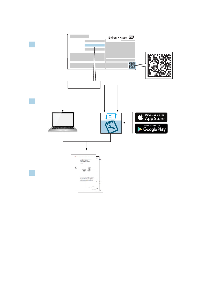
1.4 Documentation ........................................................................ 5
2 Basic safety instructions .......................................................... 6
2.1 Requirements for personnel .............................................................. 6
2.2 Designated use ........................................................................ 6
2.3 Workplace safety ...................................................................... 7
2.4 Operational safety ......................................................................7
2.5 Product safety ......................................................................... 7
3 Incoming acceptance and product identification ................................... 9
3.1 Incoming acceptance .................................................................... 9
3.2 Product identification ................................................................... 9
3.3 Scope of delivery ...................................................................... 10
4 Installation ...................................................................... 11
4.1 Mounting conditions ................................................................... 11
4.2 Mounting the measuring device ...........................................................12
4.3 Post-installation check ................................................................. 15
5 Electrical connection ............................................................ 16
5.1 Connecting the measuring device ......................................................... 16
5.2 Connecting the sensors ................................................................. 23
5.3 Connecting additional inputs, outputs or relays ............................................... 27
5.4 Connecting PROFIBUS or Modbus 485 ...................................................... 30
5.5 Hardware settings ..................................................................... 34
5.6 Ensuring the degree of protection ......................................................... 35
5.7 Post-connection check ..................................................................36
6 Operation options ............................................................... 37
6.1 Overview ........................................................................... 37
6.2 Access to the operating menu via the local display ............................................. 38
7 Commissioning .................................................................. 39
7.1 Function check ....................................................................... 39
7.2 Switching on ......................................................................... 39
7.3 Basic setup .......................................................................... 40

About this document Liquiline CM442/CM444/CM448
4 Endress+Hauser
1 About this document
1.1 Warnings
Structure of information Meaning
LDANGER
Causes (/consequences)
If necessary, Consequences of non-
compliance (if applicable)
‣Corrective action
This symbol alerts you to a dangerous situation.
Failure to avoid the dangerous situation will result in a fatal or serious injury.
LWARNING
Causes (/consequences)
If necessary, Consequences of non-
compliance (if applicable)
‣Corrective action
This symbol alerts you to a dangerous situation.
Failure to avoid the dangerous situation can result in a fatal or serious injury.
LCAUTION
Causes (/consequences)
If necessary, Consequences of non-
compliance (if applicable)
‣Corrective action
This symbol alerts you to a dangerous situation.
Failure to avoid this situation can result in minor or more serious injuries.
NOTICE
Cause/situation
If necessary, Consequences of non-
compliance (if applicable)
‣Action/note
This symbol alerts you to situations which may result in damage to property.
1.2 Symbols
Symbol Meaning
Additional information, tips
Permitted or recommended
Not permitted or not recommended
Reference to device documentation
Reference to page
Reference to graphic
Result of a step

Liquiline CM442/CM444/CM448 About this document
Endress+Hauser 5
1.3 Symbols on the device
Symbol Meaning
Reference to device documentation
1.4 Documentation
The following instructions complement these Brief Operating Instructions and are available on
the product pages on the Internet:
• Operating Instructions Liquiline CM44x, BA00444C
• Device description
• Commissioning
• Operation
• Software description (excluding sensor menus; these are described in a separate manual -
see below)
• Device-specific diagnostics and troubleshooting
• Maintenance
• Repair and spare parts
• Accessories
• Technical data
• Operating Instructions Memosens, BA01245C
• Software description for Memosens inputs
• Calibration of Memosens sensors
• Sensor-specific diagnostics and troubleshooting
• Operating Instructions for HART communication, BA00486C
• Onsite settings and installation instructions for HART
• Description of HART driver
• Guidelines for communication via fieldbus and web server
• HART, SD01187C
• PROFIBUS, SD01188C
• Modbus, SD01189C
• Web server, SD01190C
• EtherNet/IP, SD01293C
• PROFINET, SD02490C
• Safety instructions for electrical apparatus in explosion-hazardous areas
• ATEX & IECEx, XA02419C
• CSA, XA02420C

Basic safety instructions Liquiline CM442/CM444/CM448
6 Endress+Hauser
2 Basic safety instructions
2.1 Requirements for personnel
• Installation, commissioning, operation and maintenance of the measuring system may be
carried out only by specially trained technical personnel.
• The technical personnel must be authorized by the plant operator to carry out the specified
activities.
• The electrical connection may be performed only by an electrical technician.
• The technical personnel must have read and understood these Operating Instructions and
must follow the instructions contained therein.
• Faults at the measuring point may only be rectified by authorized and specially trained
personnel.
Repairs not described in the Operating Instructions provided must be carried out only
directly at the manufacturer's site or by the service organization.
2.2 Designated use
2.2.1 Non-hazardous atmosphere
Liquiline CM44x is a multichannel controller for connecting digital sensors with Memosens
technology in non-hazardous environments.
The device is designed for use in the following applications:
• Water and wastewater
• Power stations
• Chemical industry
• Other industrial applications
2.2.2 Hazardous environment in accordance with cCSAus Class I Div. 2
‣Please pay attention to the control drawing and specified operating conditions in the
appendix of the Operating Instructions and follow the instructions.
2.2.3 Transmitter in non-explosion-hazardous environment with sensor
communication module 2DS Ex-i for sensors in explosion-hazardous
environment
The installation conditions in these Brief Operating Instructions and the corresponding XA
must be observed.
• ATEX & IECEx: XA02419C
• CSA: XA02420C
2.2.4 Non-designated use
Use of the device for any purpose other than that described, poses a threat to the safety of
people and of the entire measuring system and is therefore not permitted.
The manufacturer is not liable for damage caused by improper or non-designated use.

Liquiline CM442/CM444/CM448 Basic safety instructions
Endress+Hauser 7
2.3 Workplace safety
As the user, you are responsible for complying with the following safety conditions:
• Installation guidelines
• Local standards and regulations
• Regulations for explosion protection
Electromagnetic compatibility
• The product has been tested for electromagnetic compatibility in accordance with the
applicable international standards for industrial applications.
• The electromagnetic compatibility indicated applies only to a product that has been
connected in accordance with these Operating Instructions.
2.4 Operational safety
Before commissioning the entire measuring point:
1. Verify that all connections are correct.
2. Ensure that electrical cables and hose connections are undamaged.
3. Do not operate damaged products, and protect them against unintentional operation.
4. Label damaged products as defective.
During operation:
‣If faults cannot be rectified:
products must be taken out of service and protected against unintentional operation.
LCAUTION
Cleaning not switched off during calibration or maintenance activities
Risk of injury due to medium or cleaning agent!
‣If a cleaning system is connected, switch it off before removing a sensor from the medium.
‣If you wish to check the cleaning function and have therefore not switched off the cleaning
system, wear protective clothing, goggles and gloves or take other appropriate measures.
2.5 Product safety
2.5.1 State-of-the-art technology
The product is designed to meet state-of-the-art safety requirements, has been tested, and
left the factory in a condition in which it is safe to operate. The relevant regulations and
international standards have been observed.
2.5.2 IT security
We only provide a warranty if the device is installed and used as described in the Operating
Instructions. The device is equipped with security mechanisms to protect it against any
inadvertent changes to the device settings.

Basic safety instructions Liquiline CM442/CM444/CM448
8 Endress+Hauser
IT security measures in line with operators' security standards and designed to provide
additional protection for the device and device data transfer must be implemented by the
operators themselves.

Liquiline CM442/CM444/CM448 Incoming acceptance and product identification
Endress+Hauser 9
3 Incoming acceptance and product identification
3.1 Incoming acceptance
1. Verify that the packaging is undamaged.
Notify the supplier of any damage to the packaging.
Keep the damaged packaging until the issue has been resolved.
2. Verify that the contents are undamaged.
Notify the supplier of any damage to the delivery contents.
Keep the damaged goods until the issue has been resolved.
3. Check that the delivery is complete and nothing is missing.
Compare the shipping documents with your order.
4. Pack the product for storage and transportation in such a way that it is protected
against impact and moisture.
The original packaging offers the best protection.
Make sure to comply with the permitted ambient conditions.
If you have any questions, please contact your supplier or your local Sales Center.
3.2 Product identification
3.2.1 Nameplate
Nameplates can be found:
• on the outside of the housing
• on the packaging (adhesive label, portrait format)
• on the inside of the display cover
The nameplate provides you with the following information on your device:
• Manufacturer identification
• Order code
• Extended order code
• Serial number
• Firmware version
• Ambient and process conditions
• Input and output values
• Activation codes
• Safety information and warnings
• Ex marking on hazardous area versions
‣Compare the information on the nameplate with the order.

Incoming acceptance and product identification Liquiline CM442/CM444/CM448
10 Endress+Hauser
3.2.2 Product identification
Product page
www.endress.com/cm442
www.endress.com/cm444
www.endress.com/cm448
Interpreting the order code
The order code and serial number of your product can be found in the following locations:
• On the nameplate
• In the delivery papers
Obtaining information on the product
1. Go to www.endress.com.
2. Call up the site search (magnifying glass).
3. Enter a valid serial number.
4. Search.
The product structure is displayed in a popup window.
5. Click on the product image in the popup window.
A new window (Device Viewer) opens. All of the information relating to your
device is displayed in this window as well as the product documentation.
3.2.3 Manufacturer address
Endress+Hauser Conducta GmbH+Co. KG
Dieselstraße 24
D-70839 Gerlingen
3.3 Scope of delivery
The scope of delivery comprises:
• 1 multichannel controller in the version ordered
• 1 mounting plate
• 1 wiring label (attached at the factory to the inside of the display cover)
• 1 printed copy of the Brief Operating Instructions in the language ordered
• Disconnection element (pre-installed on hazardous area version type 2DS Ex-i)
‣If you have any queries:
Please contact your supplier or local sales center.

Liquiline CM442/CM444/CM448 Installation
Endress+Hauser 11
4 Installation
4.1 Mounting conditions
4.1.1 Mounting plate
80 (3.15)
190 (7.48)
3 (0.12)
4 x 6.5 (0.26)
170 (6.69)
125 (4.92)
A0012426
1 Mounting plate, dimensions in mm (in)

Installation Liquiline CM442/CM444/CM448
12 Endress+Hauser
4.1.2 Weather protection cover
NOTICE
Effect of climatic conditions (rain, snow, direct sunlight etc.)
Impaired operation to complete transmitter failure are possible!
‣Always use the weather protection cover (accessory) when installing the device outdoors.
320 (12.6)
270 (10.6)
300 (11.8)
80 (3.15)
170 (6.69)
170 (6.69)
80 (3.15)
8 x Ø 7 (0.28)
A0012428
2 Dimensions in mm (in)
4.2 Mounting the measuring device
4.2.1 Post mounting
You require the post mounting kit (optional) to mount the unit on a pipe, post or railing
(square or circular, clamping range 20 to 61 mm (0.79 to 2.40")).

Liquiline CM442/CM444/CM448 Installation
Endress+Hauser 13
1234
56
7
8
A0033044
3 Post mounting
1 Weather protection cover (optional) 5 Spring washers and nuts (post mounting kit)
2 Post mounting plate (post mounting kit) 6 Pipe or railing (circular/square)
3 Spring washers and nuts (post mounting kit) 7 Mounting plate
4 Pipe clamps (post mounting kit) 8 Threaded rods (post mounting kit)
A0033045
4 Post mounting
A0025885
5 Attach the device and click it into place
1. Place the device on the mounting plate.
2. Slide the device downwards in the guide on the mounting rail until it clicks into place.

Installation Liquiline CM442/CM444/CM448
14 Endress+Hauser
4.2.2 Rail mounting
1 2 34
56
7
8
9
A0012668
6 Rail mounting
1 Weather protection cover (optional) 6 Pipe or railing (circular/square)
2 Post mounting plate (post mounting kit) 7 Mounting plate
3 Spring washers and nuts (post mounting kit) 8 Threaded rods (post mounting kit)
4 Pipe clamps (post mounting kit) 9 Screws (post mounting kit)
5 Spring washers and nuts (post mounting kit)
A0025886
7 Rail mounting
A0027803
8 Attach the device and click it into place
1. Place the device on the mounting plate.
2. Slide the device downwards in the guide on the mounting rail until it clicks into place.

Liquiline CM442/CM444/CM448 Installation
Endress+Hauser 15
4.2.3 Wall mounting
≥340 (13.4)
≥150 (5.91)
A0012686
9 Installation clearance in mm (in)
1
3
4
2
A0027798
10 Wall mounting
1 Wall
24 drill holes 1)
3 Mounting plate
4 Screws Ø 6 mm (not part of scope of supply)
1)The size of the drill holes depends on the wall plugs used. The wall plugs and screws must be provided by the customer.
A0027799
11 Wall mounting
A0027797
12 Attach the device and click it into place
1. Place the device on the mounting plate.
2. Slide the device downwards in the guide on the mounting rail until it clicks into place.
4.3 Post-installation check
1. After installation, check the transmitter for damage.
2. Check whether the transmitter is protected against precipitation and direct sunlight
(e.g. by the weather protection cover).

Electrical connection Liquiline CM442/CM444/CM448
16 Endress+Hauser
5 Electrical connection
5.1 Connecting the measuring device
LWARNING
Device is live!
Incorrect connection may result in injury or death!
‣The electrical connection may be performed only by an electrical technician.
‣The electrical technician must have read and understood these Operating Instructions and
must follow the instructions contained therein.
‣Prior to commencing connection work, ensure that no voltage is present on any cable.
NOTICE
The device does not have a power switch!
‣Provide a protected circuit breaker in the vicinity of the device at the place of installation.
‣The circuit breaker must be a switch or power switch, and must be labeled as the circuit
breaker for the device.
‣At the supply point, the power supply must be isolated from dangerous live cables by
double or reinforced insulation in the case of devices with a 24 V supply voltage.
5.1.1 Opening the housing
NOTICE
Pointed or sharp tools
If unsuitable tools are used, they can scratch the housing or damage the seal, and thus have a
negative impact on the leak-tightness of the housing!
‣Do not use pointed or sharp objects,e.g. knives, to open the housing.
‣Only use a suitable Phillips screwdriver.
1.
2. 3.
4.
13 Releasing housing screws in a diagonally
opposite sequence with Phillips screwdriver
≤180°
14 Opening display cover, max. opening angle
180˚ (depends on installation position)
1. Release the housing screws on a step-by-step basis. Start with any screw of your choice.
Then release the screw diagonally opposite this screw etc.
2. To close the housing: tighten the screws in a similar step-by-step, diagonally opposite
sequence.

Liquiline CM442/CM444/CM448 Electrical connection
Endress+Hauser 17
5.1.2 Cable mounting rail
1 2 4
A0046023
15 Cable mounting rail and associated function (field device)
1 Cable mounting rail 3 Additional threaded bolts for ground connections
2 Threaded bolt (protective ground connection, central
grounding point)
4 Cable clamps (fixing and grounding the sensor cables)
5.1.3 Connecting the cable shield
Only use terminated original cables where possible. The sensor, fieldbus and Ethernet
cables must be shielded cables.
Clamping range of cable clamps: 4 to 11 mm (0.16 to 0.43 in)
Sample cable (does not necessarily correspond to the original cable supplied)
12
3
16 Terminated cable
1 Outer shield (exposed)
2 Cable cores with ferrules
3 Cable sheath (insulation)
4
A0045763
17 Connect the cable to the
grounding clamp
4 Grounding clamp
A0045764
18 Press the cable into the
grounding clamp
The cable shield is grounded using the
grounding clamp 1)
1) Please note the instructions in the "Ensuring the degree of protection" section (→ 35)
1. Loosen a suitable cable gland on the bottom of the housing.
2. Remove the dummy plug.

Electrical connection Liquiline CM442/CM444/CM448
18 Endress+Hauser
3. Attach the gland to the cable end, making sure the gland is facing the right direction.
4. Pull the cable through the gland and into the housing.
5. Route the cable in the housing in such a way that the exposed cable shield fits into one
of the cable clamps and the cable cores can be easily routed as far as the connection plug
on the electronics module.
6. Connect the cable to the cable clamp.
7. Clamp the cable.
8. Connect cable cores as per the wiring diagram.
9. Tighten the cable gland from outside.
5.1.4 Cable terminals
Plug-in terminals for Memosens and PROFIBUS/RS485 connections
‣Press the screwdriver against the
clip (opens the terminal).
‣Insert the cable until the limit stop. ‣Remove the screwdriver (closes the
terminal).
After connection, make sure that every cable end is securely in place. Terminated cable
ends, in particular, tend to come loose easily if they have not been correctly inserted as
far as the limit stop.

Liquiline CM442/CM444/CM448 Electrical connection
Endress+Hauser 19
All other plug-in terminals
‣Press the screwdriver against the
clip (opens the terminal).
‣Insert the cable until the limit stop. ‣Remove the screwdriver (closes the
terminal).
5.1.5 Connecting the supply voltage for the CM442
N/- L/+
PE
A0039627
19 Connecting power supply on the BASE2-H
or -L
H Power unit 100 to 230 VAC
L Power unit 24 VAC or 24 VDC
85
85
86
86
SD
Display
Sensor supply
+
+
–
Service
PK
GY
PK
GY
1
2
–
L
N
*
Power
L/+
N/–
PE
+
–
A
B
41
43
42
Alarm
31
31
32
32
0/4 ... 20 mA
+
+
–
–
HART
+
–
A
B
Sensor 2
Ethernet
87
88
97
98
87
88
97
98
BN
WH
GN
YE
BN
WH
GN
YE
Sensor 1
1
2
A0039625
20 Overall wiring diagram for BASE2-H or -L

Electrical connection Liquiline CM442/CM444/CM448
20 Endress+Hauser
Connecting the supply voltage
1. Route the power supply cable into the housing through the suitable cable entry.
2. Step 2 applies only to the 100 to 230 V AC power unit.
Connect the protective ground of the power unit to the threaded bolt specially provided
on the cable mounting rail.
3. Protective ground or grounding provided by customer (absolutely essential for 24 V
power unit, additionally recommended for 100 to 230 V AC power unit): Provide a
ground cable (min. 0.75 mm2 (corresponding to 18 AWG))1! Guide the ground cable
also through the cable entry and connect it to the threaded bolt on the cable mounting
rail.
4. Connect the cable cores L and N (100 to 230 V AC) or + and ‐ (24 V DC) to the plug-in
terminals on the power unit in accordance with the wiring diagram.
1 2 345
21 Protective ground or grounding
connection
1 Protective ground of power unit
2 Serrated washer and nut
3 Protective ground / ground cable, provided by customer
(min. 0.75 mm2 ( 18 AWG)) 1)
4 Serrated washer and nut
5 Mounting bolts
1) For a fuse with a rating of 10 A. For a fuse with a rating of 16 A, the protective ground / ground cable must have
a cross-sectional area of at least 1.5 mm2 ( 14 AWG).
NOTICE
Protective ground/ground cable with end sleeve or open cable lug
The cable can become loose. Loss of the protective function!
‣To connect the protective ground or ground cable to the threaded bolt, only use a cable
with a closed cable lug as per DIN 46211, 46225, form A.
‣Never connect the protective ground or ground cable to the threaded bolt with an end
sleeve or an open cable lug!
Other manuals for Liquiline CM442
10
This manual suits for next models
2
Table of contents
Other Endress+Hauser Control Panel manuals
Popular Control Panel manuals by other brands

Euromatic
Euromatic Q81S instruction manual

Visonic
Visonic PowerMaster-360R Installer's guide

Whelen Engineering Company
Whelen Engineering Company WeCanX CCTL7 installation guide

Bosch
Bosch AMAX panel 2100 Quick start manual

JCM Technologies
JCM Technologies M42 user manual

Stahl
Stahl 8220 Series operating instructions