Endress+Hauser ControlCare SPC350 User manual

ControlCare SPC350
BA046S/04/en/03.06
Version 1.00.xx
70103681
Operating Instructions
ControlCare SPC350
15" and 19" Panel PCs with P View Software


ControlCare Panel PC SPC350 Table of Contents
Endress+Hauser 1
Table of Contents
Revision History . . . . . . . . . . . . . . . . . . . . . . . . . . . 2
Registered Trademarks . . . . . . . . . . . . . . . . . . . . . . 2
1 Safety . . . . . . . . . . . . . . . . . . . . . . . . . . 3
1.1 Designated used . . . . . . . . . . . . . . . . . . . . . . . . . . . 3
1.2 Installation, commissioning and operation . . . . . . . . 3
1.3 Operational safety . . . . . . . . . . . . . . . . . . . . . . . . . . 3
1.4 Declaration of conformity . . . . . . . . . . . . . . . . . . . . 3
1.5 Technical improvement . . . . . . . . . . . . . . . . . . . . . . 3
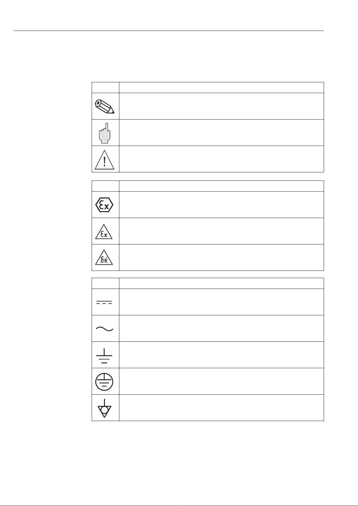
1.6 Conventions and icons . . . . . . . . . . . . . . . . . . . . . . 4
2 Identification . . . . . . . . . . . . . . . . . . . . 5
2.1 Unpacking . . . . . . . . . . . . . . . . . . . . . . . . . . . . . . . . 5
2.1.1 Visual check . . . . . . . . . . . . . . . . . . . . . . . . 5
2.1.2 Scope of delivery . . . . . . . . . . . . . . . . . . . . . 5
2.1.3 Storage and transport . . . . . . . . . . . . . . . . . . 5
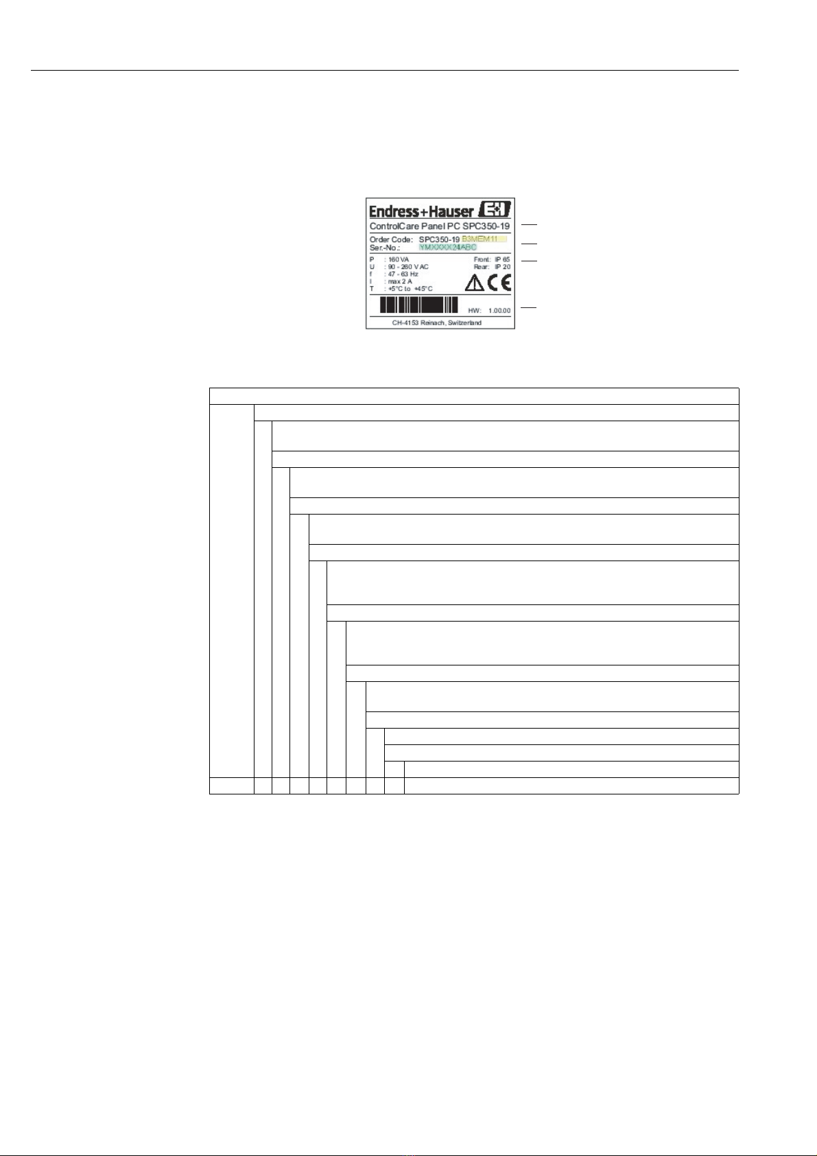
2.2 Device name . . . . . . . . . . . . . . . . . . . . . . . . . . . . . . 6
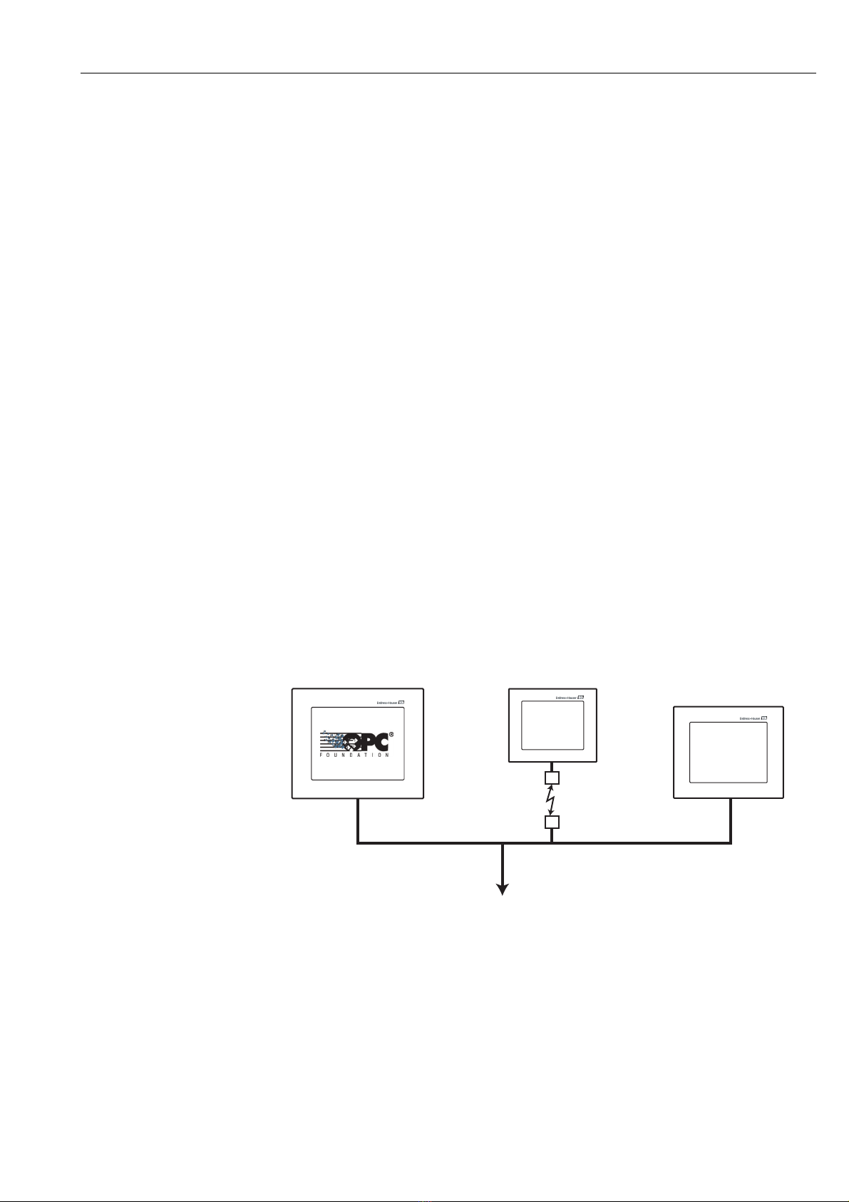
3 Function and System Design . . . . . . . . 7
3.1 Function . . . . . . . . . . . . . . . . . . . . . . . . . . . . . . . . . 7
3.2 System design . . . . . . . . . . . . . . . . . . . . . . . . . . . . . 7
4 Mechanical Installation . . . . . . . . . . . . 8
4.1 Location . . . . . . . . . . . . . . . . . . . . . . . . . . . . . . . . . 8
4.1.1 Temperature . . . . . . . . . . . . . . . . . . . . . . . . 8
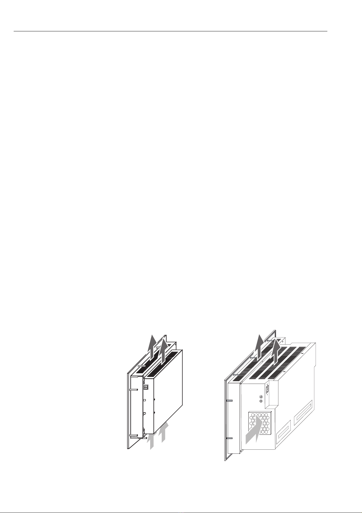
4.1.2 Ventilation . . . . . . . . . . . . . . . . . . . . . . . . . 8
4.2 Installation of the 15" monitor . . . . . . . . . . . . . . . . . 9
4.2.1 Cut-out . . . . . . . . . . . . . . . . . . . . . . . . . . . . 9
4.2.2 Fastening and sealing . . . . . . . . . . . . . . . . . . 9
4.3 Installation of the 19" monitor . . . . . . . . . . . . . . . . 10
4.3.1 Cut-out . . . . . . . . . . . . . . . . . . . . . . . . . . . 10
4.3.2 Fastening and sealing . . . . . . . . . . . . . . . . . 10
5 Electrical Installation . . . . . . . . . . . . . 11
5.1 General precautions . . . . . . . . . . . . . . . . . . . . . . . . 11
5.2 Power supply 15" monitor . . . . . . . . . . . . . . . . . . . 12
5.2.1 24 VDC power supply . . . . . . . . . . . . . . . . 12
5.2.2 Plug connector . . . . . . . . . . . . . . . . . . . . . 12
5.3 Power supply 19" monitor . . . . . . . . . . . . . . . . . . . 13
5.3.1 230 VAC plug connector . . . . . . . . . . . . . . 13
5.4 Peripherals . . . . . . . . . . . . . . . . . . . . . . . . . . . . . . 14
5.4.1 Access 15" monitor . . . . . . . . . . . . . . . . . . 14
5.4.2 Access 19" monitor . . . . . . . . . . . . . . . . . . 14
5.4.3 Keyboard . . . . . . . . . . . . . . . . . . . . . . . . . . 15
5.4.4 Mouse . . . . . . . . . . . . . . . . . . . . . . . . . . . . 15
5.4.5 Printer . . . . . . . . . . . . . . . . . . . . . . . . . . . 15
5.4.6 Monitor . . . . . . . . . . . . . . . . . . . . . . . . . . 15
5.4.7 Ethernet network . . . . . . . . . . . . . . . . . . . 15
5.4.8 Hardware extensions . . . . . . . . . . . . . . . . . 15
5.5 External interfaces . . . . . . . . . . . . . . . . . . . . . . . . . 16
5.5.1 Serial port COM1 [RS-232] . . . . . . . . . . . . 16
5.5.2 Ethernet ports . . . . . . . . . . . . . . . . . . . . . . 16
5.5.3 USB ports . . . . . . . . . . . . . . . . . . . . . . . . . 16
5.5.4 VGA port . . . . . . . . . . . . . . . . . . . . . . . . . . 17
5.5.5 PS/2 mouse port . . . . . . . . . . . . . . . . . . . . 17
5.5.6 PS/2 keyboard port . . . . . . . . . . . . . . . . . . 17
5.5.7 PROFIBUS DP port . . . . . . . . . . . . . . . . . . 18
5.5.8 Parallel LPT1 port . . . . . . . . . . . . . . . . . . . 18
6 Commissioning and Operation . . . . . 19
6.1 Start-up . . . . . . . . . . . . . . . . . . . . . . . . . . . . . . . . . 19
6.2 Operation . . . . . . . . . . . . . . . . . . . . . . . . . . . . . . . 19
6.3 Maintenance . . . . . . . . . . . . . . . . . . . . . . . . . . . . . 19
6.3.1 Display backlights . . . . . . . . . . . . . . . . . . . 19
7 Technical Data . . . . . . . . . . . . . . . . . 20
7.1 Panel PC Specification . . . . . . . . . . . . . . . . . . . . . . 20
7.2 Operating Conditions . . . . . . . . . . . . . . . . . . . . . . . 21
7.3 Mechanical Construction . . . . . . . . . . . . . . . . . . . . 21
7.4 Certificates and Approvals . . . . . . . . . . . . . . . . . . . 21
Index . . . . . . . . . . . . . . . . . . . . . . . . . 24

ControlCare Panel PC SPC350
2Endress+Hauser
Revision History
Registered Trademarks
PROFIBUS®
Registered trademark of the PROFIBUS User Organisation, Karlsruhe Germany.
FOUNDATIONTM Fieldbus
Trademark of the Fieldbus Foundation, Austin, TX 78759, USA
HART®
Registered trademark of the HART Communication Foundation, Houston, USA
Microsoft®, Windows® , Windows 2000®,Windows XP® and the Microsoft logo are registered
trademarks of the Microsoft Corporation.
Acrobat Reader®is a registered trade mark of the Adobe Systems Incorporated.
All other brand and product names are trademarks or registered trademarks of the companies and
organisations in question
Product
version
Manual Changes Remarks
1.00.xx BA046S/04/en/03.06 Original

ControlCare Panel PC SPC350 1Safety
Endress+Hauser 3
1Safety
1.1 Designated used
ControlCare Panel PC SPC350 is an industrial computer with integrated 15" or 19" touchscreen as
well as P View server software. The device can also be used as a P View client or Web-client. The
Panel PC may be used only as described in this manual and only with the components
recommended by Endress+Hauser, which where necessary must have appropriate certification.
1.2 Installation, commissioning and operation
ControlCare Panel PC SPC350 must be installed, connected, operated and maintained according to
the instructions in this manual: personnel must be authorised and suitably qualified.
Prerequisites for proper and safe operation of the product are its correct transport, correct storage,
installation and mounting as well as careful operation and maintenance.
1.3 Operational safety
Operational environment ControlCare Panel PC SPC350 fulfils the harmonised, European standards (EN) for the various
environments in which is designed to operate. The permissible operating conditions as described in
the technical data must be upheld.
Explosion hazardous areas The device may not be installed in explosion hazardous areas.
Repair Do not open the device housing. It contains no components that need be maintained or can be
repaired by the user. In the event of a fault or defect, return the device to the manufacturer. Opening
the device housing invalidates the guarantee.
1.4 Declaration of conformity
CE Mark ControlCare Panel PC SPC350 fulfils the requirements of the EU Directive 89/336/EEC
"Electromagnetic Combatibility" (EMC Directive).
• Interference emmision: EN 50022:1998 Classe A (Product standard ITE)
EN 50011:1998 Group 1 Classe A (Product standard ISM)
• Interference Immunity: EN 50082-2:1996 for version with 15" monitor
IEC 61000-6-2: 1999 for version with 19" monitor
Interference Immunity: Industrial Environment
4A declaration in accordance with the above-mention standards has been issued and can be acquired
from Endress+Hauser Process Solutions AG.
1.5 Technical improvement
Endress+Hauser reserves the right to make technical improvements to its software and equipment
at any time and without prior notification. Where such improvements have no effect on the
operation of the equipment, they are not documentated. If the improvements effect operation, a
new version of the operating instructions is normally issued.

1Safety ControlCare Panel PC SPC350
4Endress+Hauser
1.6 Conventions and icons
In order to highlight safety relevant or alternative operating procedures in the manual, the following
conventions have been used, each indicated by a corresponding icon in the margin.
Safety conventions
Explosion protection .
Electrical symbols .
Icon Meaning
A note highlights actions or procedures which, if not performed correctly, may indirectly affect operation
or may lead to an instrument response which is not planned
Caution!
Caution highlights actions or procedures which, if not performed correctly, may lead to personal injury or
incorrect functioning of the instrument
Warning!
A warning highlights actions or procedures which, if not performed correctly, will lead to personal injury,
a safety hazard or destruction of the instrument
Icon Meaning
Device certified for use in explosion hazardous area
If the device has this symbol embossed on its name plate it can be installed in an explosion hazardous area
in accordance with the specifications in the certificate or in a safe area
Explosion hazardous area
Symbol used in drawings to indicate explosion hazardous areas. Devices located in and wiring entering
areas with the designation “explosion hazardous areas” must conform with the stated type of protection
Safe area (non-explosion hazardous area)
Symbol used in drawings to indicate, if necessary, non-explosion hazardous areas. Devices located in safe
areas stiill require a certificate if their outputs run into explosion hazardous areas.
Icon Meaning
Direct voltage
A terminal to which or from which a direct current or voltage may be applied or supplied
Alternating voltage
A terminal to which or from which an alternating (sine-wave) current or voltage may be applied or
supplied
Grounded terminal
A grounded terminal, which as far as the operator is concerned, is already grounded by means of an earth
grounding system
Protective grounding (earth) terminal
A terminal which must be connected to earth ground prior to making any other connection to the
equipment
Equipotential connection (earth bonding)
A connection made to the plant grounding system which may be of type e.g. neutral star or equipotential
line according to national or company practice

ControlCare Panel PC SPC350 2 Identification
Endress+Hauser 5
2 Identification
2.1 Unpacking
2.1.1 Visual check
When unpacking:
• Check the packaging of the ControlCare Panel PC SPC350 for visible transport damage
• To avoid damage when unpacking, remove the packing material with care
• Keep the original packing for any further transport of the ControlCare Panel PC SPC350
• Store the accompanying documents in a safe place
If you find that the Panel PC has been damaged in any way, do not put it into operation. In this case,
contact your Endress+Hauser Sales Center. Return the device, where possible in the original
packing, to us.
2.1.2 Scope of delivery
Before installing the device, please check that the delivery is complete and undamaged. The scope
of delivery comprises:
• ControlCare Panel PC SPC350 with preinstalled P View software
• CD-ROM with operating instructions
Options:
• Keyboard with trackball
• Keyboard and mouse
• External floppy drive
• External DVD-RW drive
2.1.3 Storage and transport
Although ControlCare Panel PC SPC350 is of robust construction, some of its components are
sensitive to heavy vibrations and shocks. For this reason, the ControlCare Panel PC SPC350 must
be protected against excessive mechanical loads.
The device may only be transported in its original packing, complete with shock-absorbing
components. Make sure that no condensation can form on or within the device when it is
transported in cold weather or is subject to extreme temperature differences.

2 Identification ControlCare Panel PC SPC350
6Endress+Hauser
2.2 Device name
The device name and order code are to be found on the nameplate, which is located at the rear of
the housing.
The device type can be derived from the product code by using the table below:
SPC350 ControlCare Panel PC as P View Server or Client, as appropriate
Monitor Size
15
19
15"
19"
Memory Extension
A
B
512 MB
1024 MB
Hard Disk
1
2
40 MB
100 MB
Keyboard
A
C
M
No keyboard
Compact keyboard with trackball
Keyboard and optical mouse
Hardware Extension
A
B
C
Without
Floppy drive via USB
DVD-RW via USB
PROFIBUS
A
M
No PROFIBUS
PROFIBUS Master
Slot Extension
1Notused
Additional option
1Notused
SPC350
Name
Device information
Technical data
Barcode

ControlCare Panel PC SPC350 3 Function and System Design
Endress+Hauser 7
3 Function and System Design
3.1 Function
ControlCare SPC350 is an industrial PC with preinstalled operating system, Internet Explorer and
P View Server software. The device can also be used as a P View client or Web-client. It is supplied
as part of a packaged solution that also includes a P View SCADA application.
The P View SCADA application acquires process data from the system network via OPC server. The
data is then visualized in various HMI pages that are designed according to customer specifications.
Since P View supports a client-server architecture, the HMI pages can be viewed in every P View
client connected to the system.
The P View client or P View Web-client and the P View server communicate via Ethernet in
Intranet/Internet, which can be protected with firewalls or other safety mechanisms. This allows
safe, worldwide access to the HMI pages of the P View server.
Depending upon user requirements, the P View client is automatically started and the connection
to the server established when the Panel PC is switched on. It is also possible to select the HMI
pages that are to be displayed at a particular client. Operation and navigation is via the touchscreen.
3.2 System design
Fig. 3-1 shows a monitoring system with the 19" ControlCare Panel PC acting as P View server.
Process values are collected from the system and made available to the P View clients running in
the other stations. The Web-client can be installed in an internal or external network.
Fig. 3-1: Example of system design with P View server , client and Web-client
19" ControlCare Panel PC SPC350
as P View server
e.g. in the control room
Ethernet
System
ControlCare SPC350
12" ControlCare Panel PC SPC150
as P View Web-client
e.g. in an external network
ControlCare SPC150
Network connection
15" ControlCare Panel PC SPC350
as P View client or Web-client
e.g. installed in the field
ControlCare SPC350

4 Mechanical Installation ControlCare Panel PC SPC350
8Endress+Hauser
4 Mechanical Installation
4.1 Location
ControlCare Panel PCs are designed for use in industrial environments and can be mounted in
racks, cabinets, cabinet doors, consoles or control panels. They are approved for use in closed rooms.
When installing, please observe the specifications in Chapter 7, Technical Data.
4.1.1 Temperature
The Panel PC may not be subjected to direct sunlight or other source of light.
Before installing or commissioning:
• Allow the device enough time to adapt to room temperature.
• If there is any danger of condensation, make sure that the device is absolutely dry before
switching it on.
4.1.2 Ventilation
The temperature of the surrounding air during operation may not exceed +45°C (110°F). It is
important that the device does not overheat during operation.
• Ventilation slits at the top and bottom of the housing allow air to circulate and cool the device
during operation. Ensure that these slits are always free.
• If the device is mounted in a panel, housing etc., it is important that there is no accumulation
of heat.
• Ensure that there is sufficient volume for the exchange of air within cabinets or consoles. The
clearance around the sides of the Panel PC must be min. 50 mm (2"), at the back min. 20 mm
(0.8").
• In the case of closed industrial housings, care should be taken that the air inside can circulate.
The maximum permissible temperature for such a constellation is dependent on the ability of
the housing to conduct heat and the circulation of the air inside. In all cases it must be ensured
that the temperature of the surrounding air does not exceed +45°C (110°F).
• For the 19" monitor, the filter mat must be cleaned or exchanged from time to time.
Fig. 4-1: Ventilation
15" Monitor 19" Monitor

ControlCare Panel PC SPC350 4 Mechanical Installation
Endress+Hauser 9
4.2 Installation of the 15" monitor
4.2.1 Cut-out
Fig. 4-2 shows the dimensions in mm (in) for the cut-out
Fig. 4-2: Dimensions in mm (in) for the 15" monitor cut-out
4.2.2 Fastening and sealing
Eight threaded post bolts FHS-M5-25 (PEM) on the rear of the front panel are used to fasten the
monitor in place. A 4 mm (0.2") dia. cellular rubber gasket in a machined 2 mm (0.1") groove
provides the seal.
• The cut-out for installation should be selected such that it is stabilized by the bracing in the
cabinet or panel. If necessary, bracing must be installed.
• Degree of protection IP 65 is attained only for plate thickness of 2 mm (0.1") or greater. It must
also be insured that the panel is correctly installed by skilled personnel using the M5 nuts
provided and that the rubber gasket is properly seated.
Fig. 4-3: Fastening and sealing
444 (17.5)
462.6 (18.25)
165 (6.5) 165 (6.5)
10x 5.2 (0.25)
334.8 (13.2)
146 (5.75)
323 (12.75)
Threaded post bolts
FHS-M5-25 (PEM)
Cellular rubber gasket

4 Mechanical Installation ControlCare Panel PC SPC350
10 Endress+Hauser
4.3 Installation of the 19" monitor
The monitor must be installed vertically (± 5°). If it is installed at any other angle, the approval in
accordance with EN 60950 is no longer valid.
4.3.1 Cut-out
Fig. 4-4 shows the dimensions in mm (in) for the cut-out
Fig. 4-4: Dimensions in mm (in) for the 19" monitor cut-out
4.3.2 Fastening and sealing
Ten threaded post bolts FHS-M5-25 (PEM) on the rear of the front panel are used to fasten the
monitor in place. A 4 mm (0.2") dia. cellular rubber gasket in a machined 2 mm (0.1") groove
provides the seal.
• The cut-out for installation should be selected such that it is stabilized by the bracing in the
cabinet or panel. If necessary, bracing must be installed.
• Degree of protection IP 65 is attained only for plate thickness of 2 mm (0.1") or greater. It must
also be insured that the panel is correctly installed by skilled personnel using the M5 nuts
provided and that the rubber gasket is properly seated.
Fig. 4-5: Fastening and sealing
379.2 (14.9)
10x 5.2 (0.25)
462.6 (18.25)
165 (6.5)
234.9 (9.25)
444 (17.5)
365 (14.4)
165 (6.5)
Threaded post bolts
10x FHS-M5-25 (PEM)
Cellular rubber gasket

ControlCare Panel PC SPC350 5 Electrical Installation
Endress+Hauser 11
5 Electrical Installation
ControlCare Panel PC SPC350 with 15" monitor or 19" monitor is an "IT system" in accordance
with EN 60950, with supply voltage of 24 VDC or 230 VAC respectively.
5.1 General precautions
Connection for interference free operation:
• The EMC approval requires that signal connections are made with shielded cables and metal
connectors only.
• To ensure optimal electrical shielding, all plugged connections are to be screwed or locked into
position.
• Signal cables may not be laid in the same cable trays as power cables.
• Before commissioning the system, check all cable connections.
• Ensure that the permissible values for voltages and signals are upheld.
Safe discharge of electrical disturbances:
• Connect the Panel PC and cabinet by the shortest possible route to a central earth.
• Ensure good electrical connection between Panel PC and cabinet (low-impedance).
• Use an earth connection conductor of minimum 2.5 mm² (0.1 in2) diameter.
Special precautions for 230 VAC devices:
• Connect the Panel PC to a socket with a ground contact.
• To disconnect the Panel PC from the power supply, pull out the plug.
• Where a building power socket is used, check that it is easily accessible and as near as possible
to the Panel PC.
• For cabinet mounting, a central circuit-breaker must be provided.
• The plug on the power cord is classified as a circuit-breaker as per EN 60950.
• Pull out the plug before opening the device.
Special precautions for 24 VDC devices:
• The panel PC may be connected to a safety extra low voltage (SELV) circuit only.
• The circuit transformer must fulfil the pertinent standards.

5 Electrical Installation ControlCare Panel PC SPC350
12 Endress+Hauser
5.2 Power supply 15" monitor
Before connecting up:
• Check that the power supply has the correct voltage.
• Protective earth: Connect the grounding point on the housing to the cabinet earth.
A M4x10 grounding point is to be found on the bottom right of the housing, see Fig. 5-1.
View from housing side:
Fig. 5-1: Power connections, 15" monitor
5.2.1 24 VDC power supply
ControlCare Panel PC SPC350 with 15" monitor requires a 24 VDC (18–36 VDC) power supply.
The power supply must fulfil the requirements of a safely extra low voltage (SELV) circuit to
EN 60950.
5.2.2 Plug connector
The 24 VDC socket for the plug connector is to be found on the righthand side of the housing.
Fig. 5-2: Plug connector for 24 VDC
To prepare the Panel PC for operation:
• Connect a 2-core cable to the plug supplied and insert it into socket in the Panel PC housing.
Note the polarity.
• Connect the other end of the cable to a 24 VDC power supply that fulfils the requirements of
a safely extra low voltage (SELV) circuit to EN 60950.
Socket PC 4/2-G-7,62
2-pole, pitch: 7.62 mm
Phoenix Contact
Plug PC 4/2-ST-7,62
2-pole, pitch: 7.62 mm
Phoenix Contact
Grounding point
Power supply
M4x10
24 VDC:
PC 4/2-G-7,62
Warning:
Pin assignment
Warning
24 V DC
– +
+–

ControlCare Panel PC SPC350 5 Electrical Installation
Endress+Hauser 13
5.3 Power supply 19" monitor
Before connecting up:
• Check that the power supply has the correct voltage.
• Protective earth: Connect the grounding point on the housing to the cabinet earth.
A M4x10 grounding point is to be found on the lefthand side of the housing, see Fig. 5-3.
Fig. 5-3: Power connections, 19" monitor
5.3.1 230 VAC plug connector
IEC 320 connector receptacle (3-pole, male C-14 connector)
To prepare the Panel PC for operation:
• Plug the IEC 320 connector on the detachable IEC cord set supplied into the receptacle on the
rear of the housing.
• Plug the line connector at the other end of the cord set into a line socket with a functioning
ground contact.
The AC/DC power pack requires a power supply of 230 VAC (90...260 VAC), autorange
Grounding point
Power supply
230 VAC:
IEC C-14 male connector
M4x10
Power
supply
Grounding point

5 Electrical Installation ControlCare Panel PC SPC350
14 Endress+Hauser
5.4 Peripherals
ControlCare Panel PC SPC350 offers a number of ports to which peripherals can be connected.
• When using commercial peripherals (USB, PS/2 etc.), it should be noted that their immunity
to electromagnetic interference is normally sufficient for an office environment only.
• Commercial peripherals are suitable for use during commissioning and service. If an external
mouse and keyboard are required during operation, care should be taken that they have a EMC
approval (CE mark) for use in an industrial environment.
• An external keyboard and the touchscreen can be used in parallel.
5.4.1 Access 15" monitor
The connectors for the peripherals are to be found on the lefthand side of the housing, see Fig. 5-4:
Fig. 5-4: Peripheral connectors, 15" monitor
5.4.2 Access 19" monitor
The connectors for the peripherals are to be found on the lefthand side of the housing, see Fig. 5-5:
Fig. 5-5: Peripheral connectors, 19" monitor
Ethernet 1
COM1 RS-232
COM2 RS-232 (not connected)
VGA
LPT1
PS/2 keyboard
USB0
PS/2 mouse
USB1
PROFIBUS plug (service)
PROFIBUS DP/RS-485 socket
PROFIBUS LED
Run (green) Ready (yellow)
Ethernet 2
Ethernet0
COM1 RS-232
COM2 RS-232
(not connected)
VGA
LPT1
PS/2 keyboard
USB0
PS/2 mouse
USB1
PROFIBUS (Service)
PROFIBUS DP/RS-485
female connector
PROFIBUS LED
Run (green) Ready (yellow)
Ethernet1

ControlCare Panel PC SPC350 5 Electrical Installation
Endress+Hauser 15
5.4.3 Keyboard
Various keyboard types can be connected to the ControlCare Panel PC SPC350:
• PS/2 keyboard
connected to the PS/2 keyboard socket.
• USB keyboard
connected to the USB port:
for first-time use it is usually necessary to install a USB keyboard driver.
5.4.4 Mouse
Various mouse types can be connected to the ControlCare Panel PC SPC350:
• Serial mouse
connected to the COM1 interface: the corresponding mouse driver must be installed and
configured.
• PS/2 mouse (or pointing device)
connected to the PS/2 mouse socket.
• USB mouse
connected to the USB port:
for first-time use it is usually necessary to install a USB mouse driver.
5.4.5 Printer
A printer can be connected to the LPT1 interface.
5.4.6 Monitor
An external monitor or various other display types can be connected to the VGA interface.
!Note
• It is possible that the use of an external monitor cause an loss of touchscreen picture quality.
• We recommend that external monitors are used for service and diagnosis only.
5.4.7 Ethernet network
ControlCare Panel PC SPC350 is connected to an Ethernet network via the RJ-45 socket.
• For computer-computer connections, use a crossed Ethernet cable.
• For computer-switch connections, use a standard Ethernet cable.
5.4.8 Hardware extensions
A floppy or DVD-RW drive can be connected to the USB port. The following options are available:
• External floppy drive
• External DVD-RW drive.

5 Electrical Installation ControlCare Panel PC SPC350
16 Endress+Hauser
5.5 External interfaces
5.5.1 Serial port COM1 [RS-232]
ControlCare Panel PC SPC350 has a serial port (RS-232, V24) with a 9-pin Sub-D male connector
labelled "COM 1".
Tab. 5-1: COM1 [RS-232 serial port)
5.5.2 Ethernet ports
ControlCare Panel PC SPC350 has two Ethernet ports with RJ-45 10Base-T female connector
labelled "Ethernet". The controller supports transmission rates of 10 MBit/s and 100 MBit/s.
Tab. 5-2: Ethernet
5.5.3 USB ports
ControlCare Panel PC SPC350 has two Type A 4-pin USB receptacles (double-decker) labelled
"USB A" and "USB B",
Tab. 5-3: USB [double]
Sub-D male connector
9-pin
Pin Signal Description Input/
Output
1 DCD Data Carrier Detect I
2RxD ReceiveData I
3TxD TransmitData O
4 DTR Data Terminal Ready O
5 GND Signal Ground ---
6 DSR Data Set Ready I
7 RTS Request to Send O
8CTS CleartoSend I
9 RI Ring Indicator I
10Base-T
RJ-45 CAT5
Pin Signal Description Input/Output
1 TxD+ 10Base-T Transmit Differential Output
2 TxD- 10Base-T Transmit Differential Output
3 RxD+ 10Base-T Receive Differential Input
4 N.C. not connected ---
5 N.C. not connectedt ---
6 RxD- 10Base-T Receive Differential Input
7 N.C. not connected ---
8 N.C. not connected ---
LED green Link
LED yellow Activity
USB Type A
4-pin
USB A USB B Description
1VCC1VCCPower(+5V/0,5A)
2USB0-2USB1-Data
3USB0+3USB1+Data
4GND4GNDGround
6
7
8
9
1
2
3
4
5
1
8
1
2
3
4

ControlCare Panel PC SPC350 5 Electrical Installation
Endress+Hauser 17
5.5.4 VGA port
ControlCare Panel PC SPC350 has a 15-pin HD-Sub-D port labelled "VGA".
Tab. 5-4: VGA [CRT]
5.5.5 PS/2 mouse port
ControlCare Panel PC SPC350 has a 6-pin MiniDIN port labelled "PS/2 mouse" for the connection
of an external PS/2 mouse.
Tab. 5-5: PS/2 mouse
5.5.6 PS/2 keyboard port
ControlCare Panel PC SPC350 has a 6-pin MiniDIN port labelled "PS/2 keyb" for the connection
of an external PS/2 keyboard.
Tab. 5-6: PS/2 keyboard
HD-Sub-D female
connector, 15-pin
Pin Signal Pin Signal Pin Signal
1 RED 6 GND 11 N.C.
2 GREEN 7 GND 12 DDC DAT
3BLUE 8GND 13HSYNC
4 N.C. 9 VCC_VGA (+5V) 14 VSYNC
5GND 10GND 15DDCCLK
MiniDIN female
connector, 6-pin
Pin Signal Description Input/
Output
1 MSDAT Mouse Data I/O
2 N.C. Not connected ---
3 GND Ground ---
4 VCC_PS/2 (+5V) Power O
5MSCLK MouseClock I/O
6 N.C. Not connected ---
MiniDIN female
connector, 6-pin
Pin Signal Description Input/
Output
1 KBDAT Keyboard Data I/O
2 MSDAT Mouse Data ---
3 GND Ground ---
4 VCC_PS/2 (+5V) Power O
5 KBCLK Keyboard Clock I/O
6 MSCLK Mouse Clock ---
1
5
11
15
6
10
5
3
2
4
6
5
3
2
4
6

5 Electrical Installation ControlCare Panel PC SPC350
18 Endress+Hauser
5.5.7 PROFIBUS DP port
ControlCare Panel PC SPC350 has an optional 9-pin Sub-D port labelled "PROFIBUS" for the
connection to a PROFIBUS DP network. The PC is configured as a PROFIBUS DP master .
Tab. 5-7: PROFIBUS DP (RS-485) port
The second PROFIBUS DP port is for service purposes only.
5.5.8 Parallel LPT1 port
ControlCare Panel PC SPC350 has a parallel LPT1 port that is PC/AT compatible, the signals of
which conform to the Centronics standard. Connection is via a 25-pin Sub-D socket labelled
"LPT1".
Tab. 5-8: LPT1 parallel printer port
Sub-D female connector,
9-pin
Pin Description Signal I/O
1 --- Not connected ---
2 --- Not connected ---
3 RxD/TxD-P Data Line In/Out
4 CNTR-P Repeater Control Signal Out
5 DGND Data Reference Potential ---
6 VP Power Supply positive ---
7 --- Not connected ---
8 RxD/TxD-N Data Line inverse In/Out
9 --- Not connected ---
Sub-D-Buchse, 25-polig Pin Signal Bedeutung I/O Pin Signal Bedeutung I/O
1 STB- Strobe Out 14 AFD- Auto Feed Out
2 PD0 Datenbit 0 I/O 15 ERR- Error In
3 PD1 Datenbit 1 I/O 16 INIT- Init Printer Out
4 PD2 Datenbit 2 I/O 17 SLIN- Select Input Out
5 PD3 Datenbit 3 I/O 18 GND Signal Ground ---
6 PD4 Datenbit 4 I/O 19 GND Signal Ground ---
7 PD5 Datenbit 5 I/O 20 GND Signal Ground ---
8 PD6 Datenbit 6 I/O 21 GND Signal Ground ---
9 PD7 Datenbit 7 I/O 22 GND Signal Ground ---
10 ACK- Acknowledge In 23 GND Signal Ground ---
11 BUSY+ Busy In 24 GND Signal Ground ---
12 PE+ Paper End In 25 GND Signal Ground ---
13 SLCT+ Select In
6
7
8
9
1
2
3
4
5
25
24
23
22
21
20
19
18
17
16
15
14
13
12
11
10
9
8
7
6
5
4
3
2
1
Table of contents
Other Endress+Hauser Industrial PC manuals
Popular Industrial PC manuals by other brands

Winmate
Winmate 7'' S-Series user manual

Stahl
Stahl Manta GMP IT 9 Series operating instructions

B&R
B&R Automation PC 510 user manual

AXIOMTEK
AXIOMTEK tBOX510-518-FL-24-110MRDC user manual

Moxa Technologies
Moxa Technologies DRP-C100 Series Hardware user manual

Beckhoff
Beckhoff C5 Series Installation and operating instructions