manuals.online logo
Brands
  1. Home
  2. •
  3. Brands
  4. •
  5. Endress+Hauser
  6. •
  7. Measuring Instrument
  8. •
  9. Endress+Hauser Proline Promass X 500 FOUNDATION Fieldbus User manual

Endress+Hauser Proline Promass X 500 FOUNDATION Fieldbus User manual

Other manuals for Proline Promass X 500 FOUNDATION Fieldbus

1

Other Endress+Hauser Measuring Instrument manuals

Endress+Hauser RIA452 User manual

Endress+Hauser

Endress+Hauser RIA452 User manual

Endress+Hauser probfit CPA 463S User manual

Endress+Hauser

Endress+Hauser probfit CPA 463S User manual

Endress+Hauser RIA15 User manual

Endress+Hauser

Endress+Hauser RIA15 User manual

Endress+Hauser analytikjena multi N/C pharma HT User manual

Endress+Hauser

Endress+Hauser analytikjena multi N/C pharma HT User manual

Endress+Hauser Cerabar S PMC71 User manual

Endress+Hauser

Endress+Hauser Cerabar S PMC71 User manual

Endress+Hauser Tankvision Multi Scan NXA83B User manual

Endress+Hauser

Endress+Hauser Tankvision Multi Scan NXA83B User manual

Endress+Hauser Cerabar PMP21 User manual

Endress+Hauser

Endress+Hauser Cerabar PMP21 User manual

Endress+Hauser Viomax CAS51D User manual

Endress+Hauser

Endress+Hauser Viomax CAS51D User manual

Endress+Hauser Prosonic T FMU30 User manual

Endress+Hauser

Endress+Hauser Prosonic T FMU30 User manual

Endress+Hauser SpectraSensors J22 TDLAS User manual

Endress+Hauser

Endress+Hauser SpectraSensors J22 TDLAS User manual

Endress+Hauser Proline Promass 80 User manual

Endress+Hauser

Endress+Hauser Proline Promass 80 User manual

Endress+Hauser LT1100 User manual

Endress+Hauser

Endress+Hauser LT1100 User manual

Endress+Hauser RID14 Technical specifications

Endress+Hauser

Endress+Hauser RID14 Technical specifications

Endress+Hauser SpectraSensors J22 TDLAS User manual

Endress+Hauser

Endress+Hauser SpectraSensors J22 TDLAS User manual

Endress+Hauser Deltapilot S FMB70 User manual

Endress+Hauser

Endress+Hauser Deltapilot S FMB70 User manual

Endress+Hauser Proline Prosonic Flow 93 User manual

Endress+Hauser

Endress+Hauser Proline Prosonic Flow 93 User manual

Endress+Hauser Tank Side Monitor NRF590 Manual

Endress+Hauser

Endress+Hauser Tank Side Monitor NRF590 Manual

Endress+Hauser Micropilot FMR20 Manual

Endress+Hauser

Endress+Hauser Micropilot FMR20 Manual

Endress+Hauser RIA251 User manual

Endress+Hauser

Endress+Hauser RIA251 User manual

Endress+Hauser Proline Prosonic Flow 91W Technical specifications

Endress+Hauser

Endress+Hauser Proline Prosonic Flow 91W Technical specifications

Endress+Hauser airtrol CPC 200 User manual

Endress+Hauser

Endress+Hauser airtrol CPC 200 User manual

Endress+Hauser Proline Promag P 100 Manual

Endress+Hauser

Endress+Hauser Proline Promag P 100 Manual

Endress+Hauser Levelflex FMP51 Firmware update

Endress+Hauser

Endress+Hauser Levelflex FMP51 Firmware update

Endress+Hauser Liquiline CM44 series Operator's manual

Endress+Hauser

Endress+Hauser Liquiline CM44 series Operator's manual

Popular Measuring Instrument manuals by other brands

Powerfix Profi 278296 Operation and safety notes

Powerfix Profi

Powerfix Profi 278296 Operation and safety notes

Test Equipment Depot GVT-427B user manual

Test Equipment Depot

Test Equipment Depot GVT-427B user manual

Fieldpiece ACH Operator's manual

Fieldpiece

Fieldpiece ACH Operator's manual

FLYSURFER VIRON3 user manual

FLYSURFER

FLYSURFER VIRON3 user manual

GMW TG uni 1 operating manual

GMW

GMW TG uni 1 operating manual

Downeaster Wind & Weather Medallion Series instruction manual

Downeaster

Downeaster Wind & Weather Medallion Series instruction manual

Hanna Instruments HI96725C instruction manual

Hanna Instruments

Hanna Instruments HI96725C instruction manual

Nokeval KMR260 quick guide

Nokeval

Nokeval KMR260 quick guide

HOKUYO AUTOMATIC UBG-05LN instruction manual

HOKUYO AUTOMATIC

HOKUYO AUTOMATIC UBG-05LN instruction manual

Fluke 96000 Series Operator's manual

Fluke

Fluke 96000 Series Operator's manual

Test Products International SP565 user manual

Test Products International

Test Products International SP565 user manual

General Sleep Zmachine Insight+ DT-200 Service manual

General Sleep

General Sleep Zmachine Insight+ DT-200 Service manual

Sensa Core Lacto Spark user manual

Sensa Core

Sensa Core Lacto Spark user manual

VOLTCRAFT UTS-1980 operating instructions

VOLTCRAFT

VOLTCRAFT UTS-1980 operating instructions

EBCHQ 94915 Operation manual

EBCHQ

EBCHQ 94915 Operation manual

Balluff BIP LD2-T017-01-EP-S4 Series user guide

Balluff

Balluff BIP LD2-T017-01-EP-S4 Series user guide

Pulsar IMP Lite Series instruction manual

Pulsar

Pulsar IMP Lite Series instruction manual

ETCR 6800 user manual

ETCR

ETCR 6800 user manual

manuals.online logo
manuals.online logoBrands
  • About & Mission
  • Contact us
  • Privacy Policy
  • Terms and Conditions

Copyright 2025 Manuals.Online. All Rights Reserved.

Products Solutions Services
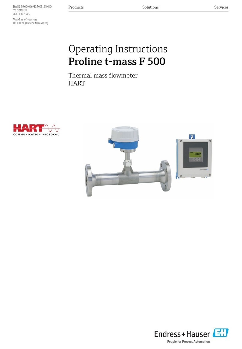
Operating Instructions
Proline Promass X 500
FOUNDATION Fieldbus
Coriolis flowmeter
K
e
e
p
c
ov
er
h
t
i
g
t
w
h
i
l
e
S
p
a
n
nu
ng
ö
f
f
n
e
n
N
ic
h
t
u
n
t
e
r
c
i
r
c
u
i
t
s
a
r
e
a
l
i
v
e
BA01569D/06/EN/01.16
71303319
Valid as of version
01.01.zz (Device firmware)
Proline Promass X 500 FOUNDATION Fieldbus
2 Endress+Hauser
• Make sure the document is stored in a safe place such that it is always available when
working on or with the device.
• To avoid danger to individuals or the facility, read the "Basic safety instructions" section
carefully, as well as all other safety instructions in the document that are specific to
working procedures.
• The manufacturer reserves the right to modify technical data without prior notice. Your
Endress+Hauser Sales Center will supply you with current information and updates to
these instructions.
Proline Promass X 500 FOUNDATION Fieldbus Table of contents
Endress+Hauser 3
Table of contents
1 Document information .............. 6
1.1 Document function ..................... 6
1.2 Symbols used .......................... 6
1.2.1 Safety symbols .................. 6
1.2.2 Electrical symbols ................ 6
1.2.3 Communication symbols ........... 6
1.2.4 Tool symbols .................... 7
1.2.5 Symbols for certain types of
information .................... 7
1.2.6 Symbols in graphics ............... 7
1.3 Documentation ........................ 8
1.3.1 Standard documentation ........... 8
1.3.2 Supplementary device-dependent
documentation .................. 8
1.4 Registered trademarks ................... 9
2 Basic safety instructions ........... 10
2.1 Requirements for the personnel ........... 10
2.2 Designated use ....................... 10
2.3 Workplace safety ...................... 11
2.4 Operational safety ..................... 11
2.5 Product safety ........................ 11
2.6 IT security ........................... 12
2.7 Device-specific IT security ................ 12
2.7.1 Protecting access via hardware write
protection ..................... 12
2.7.2 Protecting access via a password .... 12
2.7.3 Access via fieldbus ............... 13
2.7.4 Access via Web server ............ 13
3 Product description ................ 14
3.1 Product design ........................ 14
3.1.1 Proline 500 – digital ............. 14
3.1.2 Proline 500 .................... 15
4 Incoming acceptance and product
identification ..................... 16
4.1 Incoming acceptance ................... 16
4.2 Product identification ................... 16
4.2.1 Transmitter nameplate ........... 17
4.2.2 Sensor nameplate ............... 19
4.2.3 Symbols on measuring device ...... 20
5 Storage and transport ............. 21
5.1 Storage conditions ..................... 21
5.2 Transporting the product ................ 21
5.2.1 Measuring devices without lifting
lugs ......................... 21
5.2.2 Measuring devices with lifting lugs .. 22
5.2.3 Transporting with a fork lift ........ 22
5.3 Packaging disposal ..................... 22
6 Installation ....................... 22
6.1 Installation conditions .................. 22
6.1.1 Mounting position ............... 22
6.1.2 Requirements from environment and
process ....................... 24
6.1.3 Special mounting instructions ...... 27
6.2 Mounting the measuring device ........... 29
6.2.1 Required tools .................. 29
6.2.2 Preparing the measuring device ..... 30
6.2.3 Mounting the measuring device ..... 30
6.2.4 Mounting the transmitter housing:
Proline 500 – digital ............. 30
6.2.5 Mounting the transmitter housing:
Proline 500 .................... 32
6.2.6 Turning the transmitter housing:
Proline 500 .................... 33
6.2.7 Turning the display module: Proline
500 ......................... 34
6.3 Post-installation check .................. 34
7 Electrical connection .............. 35
7.1 Connection conditions .................. 35
7.1.1 Required tools .................. 35
7.1.2 Requirements for connecting cable ... 35
7.1.3 Terminal assignment ............. 38
7.1.4 Device plugs available ............ 38
7.1.5 Pin assignment of device plug ...... 39
7.1.6 Preparing the measuring device ..... 39
7.2 Connecting the measuring device .......... 40
7.2.1 Connecting the connecting cable .... 40
7.2.2 Connecting the signal cable and the
supply voltage cable ............. 44
7.3 Connecting the measuring device .......... 46
7.3.1 Connecting the connecting cable .... 46
7.3.2 Connecting the signal cable and the
supply voltage cable ............. 49
7.4 Ensure potential equalization ............. 51
7.4.1 Requirements .................. 51
7.5 Special connection instructions ............ 52
7.5.1 Connection examples ............. 52
7.6 Ensuring the degree of protection .......... 54
7.7 Post-connection check .................. 55
8 Operation options ................. 56
8.1 Overview of operation options ............ 56
8.2 Structure and function of the operating
menu .............................. 57
8.2.1 Structure of the operating menu .... 57
8.2.2 Operating philosophy ............ 58
8.3 Access to the operating menu via the local
display ............................. 59
8.3.1 Operational display .............. 59
8.3.2 Navigation view ................ 61
8.3.3 Editing view ................... 63
Table of contents Proline Promass X 500 FOUNDATION Fieldbus
4 Endress+Hauser
8.3.4 Operating elements .............. 64
8.3.5 Opening the context menu ......... 65
8.3.6 Navigating and selecting from list ... 67
8.3.7 Calling the parameter directly ...... 67
8.3.8 Calling up help text .............. 68
8.3.9 Changing the parameters ......... 69
8.3.10 User roles and related access
authorization .................. 70
8.3.11 Disabling write protection via access
code ......................... 70
8.3.12 Enabling and disabling the keypad
lock ......................... 70
8.4 Access to the operating menu via the Web
browser ............................. 71
8.4.1 Function range ................. 71
8.4.2 Prerequisites ................... 71
8.4.3 Establishing a connection ......... 73
8.4.4 Logging on .................... 75
8.4.5 User interface .................. 76
8.4.6 Disabling the Web server .......... 77
8.4.7 Logging out .................... 77
8.5 Access to the operating menu via the
operating tool ........................ 77
8.5.1 Connecting the operating tool ...... 78
8.5.2 Field Xpert SFX350, SFX370 ....... 80
8.5.3 FieldCare ..................... 81
8.5.4 DeviceCare .................... 82
8.5.5 AMS Device Manager ............ 82
8.5.6 Field Communicator 475 .......... 83
9 System integration ................ 84
9.1 Overview of device description files ......... 84
9.1.1 Current version data for the device ... 84
9.1.2 Operating tools ................. 84
9.2 Cyclic data transmission ................ 84
9.2.1 Block model ................... 84
9.2.2 Description of the modules ........ 85
9.2.3 Execution times ................. 88
9.2.4 Methods ...................... 89
10 Commissioning .................... 90
10.1 Function check ....................... 90
10.2 Switching on the measuring device ......... 90
10.3 Connecting via FieldCare ................ 90
10.4 Setting the operating language ............ 90
10.5 Configuring the measuring device .......... 91
10.5.1 Defining the tag name ............ 92
10.5.2 Setting the system units .......... 92
10.5.3 Selecting and setting the medium ... 95
10.5.4 Configuring the analog inputs ...... 97
10.5.5 Displaying the I/O configuration .... 97
10.5.6 Configuring the current input ...... 98
10.5.7 Configuring the status input ....... 99
10.5.8 Configuring the current output .... 100
10.5.9 Configuring the pulse/frequency/
switch output ................. 103
10.5.10 Configuring the relay output ...... 112
10.5.11 Configuring the local display ...... 114
10.5.12 Configuring the low flow cut off .... 117
10.5.13 Configuring the partial filled pipe
detection .................... 118
10.6 Advanced settings .................... 119
10.6.1 Using the parameter to enter the
access code ................... 120
10.6.2 Calculated values ............... 120
10.6.3 Carrying out a sensor adjustment ... 121
10.6.4 Configuring the totalizer ......... 122
10.6.5 Carrying out additional display
configurations ................. 124
10.6.6 WLAN configuration ............ 127
10.6.7 Configuration management ....... 128
10.6.8 Using parameters for device
administration ................ 129
10.7 Simulation .......................... 131
10.8 Protecting settings from unauthorized
access ............................. 134
10.8.1 Write protection via access code ... 134
10.8.2 Write protection via write protection
switch ....................... 135
10.8.3 Write protection via block
operation .................... 137
11 Operation ....................... 138
11.1 Reading the device locking status ......... 138
11.2 Adjusting the operating language ......... 138
11.3 Configuring the display ................ 138
11.4 Reading measured values ............... 138
11.4.1 "Measured variables" submenu ..... 139
11.4.2 "Totalizer" submenu ............. 140
11.4.3 "Input values" submenu .......... 141
11.4.4 Output values ................. 142
11.5 Adapting the measuring device to the process
conditions .......................... 144
11.6 Performing a totalizer reset ............. 144
11.6.1 Function scope of the "Control
Totalizer" parameter ............ 145
11.6.2 Function scope of the "Reset all
totalizers" parameter ............ 145
11.7 Showing data logging ................. 145
12 Diagnostics and troubleshooting .. 148
12.1 General troubleshooting ................ 148
12.2 Diagnostic information via light emitting
diodes ............................. 150
12.2.1 Transmitter ................... 150
12.2.2 Sensor connection housing ....... 152
12.3 Diagnostic information on local display ..... 154
12.3.1 Diagnostic message ............. 154
12.3.2 Calling up remedial measures ..... 156
12.4 Diagnostic information in the Web browser .156
12.4.1 Diagnostic options .............. 156
12.4.2 Calling up remedy information .... 157
12.5 Diagnostic information in DeviceCare or
FieldCare ........................... 157
12.5.1 Diagnostic options .............. 157
12.5.2 Calling up remedy information .... 158
Proline Promass X 500 FOUNDATION Fieldbus Table of contents
Endress+Hauser 5
12.6 Adapting the diagnostic information ...... 159
12.6.1 Adapting the diagnostic behavior ... 159
12.6.2 Adapting the status signal ........ 159
12.7 Overview of diagnostic information ....... 163
12.7.1 Diagnostic of sensor ............ 164
12.7.2 Diagnostic of electronic .......... 166
12.7.3 Diagnostic of configuration ....... 172
12.7.4 Diagnostic of process ............ 179
12.8 Pending diagnostic events .............. 184
12.9 Diagnostic messages in the DIAGNOSTIC
Transducer Block ..................... 185
12.10 Diagnostic list ....................... 185
12.11 Event logbook ....................... 186
12.11.1 Event history .................. 186
12.11.2 Filtering the event logbook ....... 187
12.11.3 Overview of information events .... 187
12.12 Resetting the measuring device .......... 188
12.12.1 Function scope of the "Restart"
parameter .................... 188
12.13 Device information ................... 189
12.14 Firmware history ..................... 190
13 Maintenance .................... 191
13.1 Maintenance tasks .................... 191
13.1.1 Exterior cleaning ............... 191
13.2 Measuring and test equipment ........... 191
13.3 Endress+Hauser services ............... 191
14 Repairs .......................... 192
14.1 General notes ....................... 192
14.1.1 Repair and conversion concept ..... 192
14.1.2 Notes for repair and conversion .... 192
14.2 Spare parts ......................... 192
14.3 Endress+Hauser services ............... 192
14.4 Return ............................. 192
14.5 Disposal ........................... 193
14.5.1 Removing the measuring device .... 193
14.5.2 Disposing of the measuring device .. 193
15 Accessories ...................... 194
15.1 Device-specific accessories .............. 194
15.1.1 For the transmitter ............. 194
15.1.2 For the sensor ................. 195
15.2 Communication-specific accessories ....... 195
15.3 Service-specific accessories .............. 195
15.4 System components ................... 196
16 Technical data ................... 197
16.1 Application ......................... 197
16.2 Function and system design ............. 197
16.3 Input .............................. 198
16.4 Output ............................ 200
16.5 Power supply ........................ 206
16.6 Performance characteristics ............. 207
16.7 Installation ......................... 211
16.8 Environment ........................ 211
16.9 Process ............................ 212
16.10 Mechanical construction ............... 214
16.11 Operability ......................... 217
16.12 Certificates and approvals .............. 221
16.13 Application packages .................. 223
16.14 Accessories ......................... 224
16.15 Supplementary documentation ........... 224
Index ................................. 226
Document information Proline Promass X 500 FOUNDATION Fieldbus
6 Endress+Hauser
1 Document information
1.1 Document function
These Operating Instructions contain all the information that is required in various phases
of the life cycle of the device: from product identification, incoming acceptance and
storage, to mounting, connection, operation and commissioning through to
troubleshooting, maintenance and disposal.
1.2 Symbols used
1.2.1 Safety symbols
Symbol Meaning
DANGER
DANGER!
This symbol alerts you to a dangerous situation. Failure to avoid this situation will
result in serious or fatal injury.
WARNING
WARNING!
This symbol alerts you to a dangerous situation. Failure to avoid this situation can
result in serious or fatal injury.
CAUTION
CAUTION!
This symbol alerts you to a dangerous situation. Failure to avoid this situation can
result in minor or medium injury.
NOTICE
NOTE!
This symbol contains information on procedures and other facts which do not result in
personal injury.
1.2.2 Electrical symbols
Symbol Meaning
Direct current
Alternating current
Direct current and alternating current
Ground connection
A grounded terminal which, as far as the operator is concerned, is grounded via a
grounding system.
Protective ground connection
A terminal which must be connected to ground prior to establishing any other
connections.
Equipotential connection
A connection that has to be connected to the plant grounding system: This may be a
potential equalization line or a star grounding system depending on national or
company codes of practice.
1.2.3 Communication symbols
Symbol Meaning
Wireless Local Area Network (WLAN)
Communication via a wireless, local network.
Bluetooth
Wireless data transmission between devices over a short distance.
Proline Promass X 500 FOUNDATION Fieldbus Document information
Endress+Hauser 7
Symbol Meaning
LED
Light emitting diode is off.
LED
Light emitting diode is on.
LED
Light emitting diode is flashing.
1.2.4 Tool symbols
Symbol Meaning
Torx screwdriver
Phillips head screwdriver
Open-ended wrench
1.2.5 Symbols for certain types of information
Symbol Meaning
Permitted
Procedures, processes or actions that are permitted.
Preferred
Procedures, processes or actions that are preferred.
Forbidden
Procedures, processes or actions that are forbidden.
Tip
Indicates additional information.
Reference to documentation
A
Reference to page
Reference to graphic
Notice or individual step to be observed
1.
,
2.
,
3.
… Series of steps
Result of a step
Help in the event of a problem
Visual inspection
1.2.6 Symbols in graphics
Symbol Meaning
1, 2, 3,... Item numbers
1.
,
2.
,
3.
… Series of steps
A, B, C, ... Views
A-A, B-B, C-C, ... Sections
Document information Proline Promass X 500 FOUNDATION Fieldbus
8 Endress+Hauser
Symbol Meaning
-
Hazardous area
.
Safe area (non-hazardous area)
Flow direction
1.3 Documentation
For an overview of the scope of the associated Technical Documentation, refer to the
following:
• The W@M Device Viewer : Enter the serial number from the nameplate
(www.endress.com/deviceviewer)
• The Endress+Hauser Operations App: Enter the serial number from the nameplate
or scan the 2-D matrix code (QR code) on the nameplate.
For a detailed list of the individual documents along with the documentation code
→  224
1.3.1 Standard documentation
Document type Purpose and content of the document
Technical Information Planning aid for your device
The document contains all the technical data on the device and provides
an overview of the accessories and other products that can be ordered for
the device.
Sensor Brief Operating Instructions Guides you quickly to the 1st measured value - Part 1
The Sensor Brief Operating Instructions are aimed at specialists with
responsibility for installing the measuring device.
• Incoming acceptance and product identification
• Storage and transport
• Installation
Transmitter Brief Operating
Instructions
Guides you quickly to the 1st measured value - Part 2
The Transmitter Brief Operating Instructions are aimed at specialists with
responsibility for commissioning, configuring and parameterizing the
measuring device (until the first measured value).
• Product description
• Installation
• Electrical connection
• Operation options
• System integration
• Commissioning
• Diagnostic information
Description of Device Parameters Reference for your parameters
The document provides a detailed explanation of each individual
parameter in the Expert operating menu. The description is aimed at
those who work with the device over the entire life cycle and perform
specific configurations.
1.3.2 Supplementary device-dependent documentation
Additional documents are supplied depending on the device version ordered: Always
comply strictly with the instructions in the supplementary documentation. The
supplementary documentation is an integral part of the device documentation.
Proline Promass X 500 FOUNDATION Fieldbus Document information
Endress+Hauser 9
1.4 Registered trademarks
FOUNDATIONTM Fieldbus
Registration-pending trademark of the FieldComm Group, Austin, Texas, USA
Applicator®, FieldCare®, DeviceCare ®, Field XpertTM, HistoROM®, Heartbeat
TechnologyTM
Registered or registration-pending trademarks of the Endress+Hauser Group
Basic safety instructions Proline Promass X 500 FOUNDATION Fieldbus
10 Endress+Hauser
2 Basic safety instructions
2.1 Requirements for the personnel
The personnel for installation, commissioning, diagnostics and maintenance must fulfill
the following requirements:
‣Trained, qualified specialists must have a relevant qualification for this specific function
and task.
‣Are authorized by the plant owner/operator.
‣Are familiar with federal/national regulations.
‣Before starting work, read and understand the instructions in the manual and
supplementary documentation as well as the certificates (depending on the
application).
‣Follow instructions and comply with basic conditions.
The operating personnel must fulfill the following requirements:
‣Are instructed and authorized according to the requirements of the task by the facility's
owner-operator.
‣Follow the instructions in this manual.
2.2 Designated use
Application and media
The measuring device described in these Brief Operating Instructions is intended only for
flow measurement of liquids and gases.
Depending on the version ordered, the measuring device can also measure potentially
explosive, flammable, poisonous and oxidizing media.
Measuring devices for use in hazardous areas, in hygienic applications or where there is an
increased risk due to process pressure, are labeled accordingly on the nameplate.
To ensure that the measuring device remains in proper condition for the operation time:
‣Only use the measuring device in full compliance with the data on the nameplate and
the general conditions listed in the Operating Instructions and supplementary
documentation.
‣Based on the nameplate, check whether the ordered device is permitted for the
intended use in the hazardous area (e.g. explosion protection, pressure vessel safety).
‣Use the measuring device only for media to which the process-wetted materials are
sufficiently resistant.
‣If the measuring device is not operated at atmospheric temperature, compliance with
the relevant basic conditions specified in the associated device documentation is
absolutely essential: "Documentation" section.→  8.
‣Protect the measuring device permanently against corrosion from environmental
influences.
Incorrect use
Non-designated use can compromise safety. The manufacturer is not liable for damage
caused by improper or non-designated use.
LWARNING
Danger of breakage due to corrosive or abrasive fluids!
‣Verify the compatibility of the process fluid with the sensor material.
‣Ensure the resistance of all fluid-wetted materials in the process.
‣Keep within the specified pressure and temperature range.