Tankvision Gauge Link
2Endress+Hauser
Table of Contents
1 Document information . . . . . . . . . . . . . . 4
1.1 Target audience for this manual . . . . . . . . . . . . . . . 4
1.2 Version history . . . . . . . . . . . . . . . . . . . . . . . . . . . . . 4
1.3 Document function . . . . . . . . . . . . . . . . . . . . . . . . . . 4
1.4 Documentation . . . . . . . . . . . . . . . . . . . . . . . . . . . . . 5
2 Basic safety instructions . . . . . . . . . . . . 6
2.1 Requirements for the personnel . . . . . . . . . . . . . . . 6
2.2 IT security . . . . . . . . . . . . . . . . . . . . . . . . . . . . . . . . . . 6
2.3 Designated use . . . . . . . . . . . . . . . . . . . . . . . . . . . . . 6
2.4 Workplace safety . . . . . . . . . . . . . . . . . . . . . . . . . . . 6
2.5 Operational safety . . . . . . . . . . . . . . . . . . . . . . . . . . . 7
2.6 Product safety . . . . . . . . . . . . . . . . . . . . . . . . . . . . . . 7
3 Identification . . . . . . . . . . . . . . . . . . . . . . 8
3.1 Product identification . . . . . . . . . . . . . . . . . . . . . . . . 8
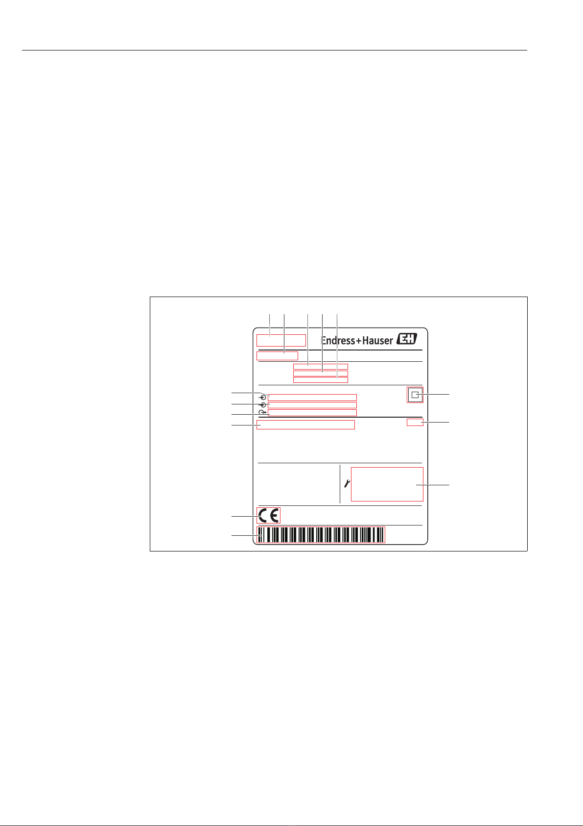
3.2 Nameplate . . . . . . . . . . . . . . . . . . . . . . . . . . . . . . . . . 8
3.3 Order code and device version . . . . . . . . . . . . . . . . . 9
3.4 Registered trademarks . . . . . . . . . . . . . . . . . . . . . . . 9
4 Introduction . . . . . . . . . . . . . . . . . . . . . . 10
4.1 Reference documentation . . . . . . . . . . . . . . . . . . 10
4.2 Communication Parameters . . . . . . . . . . . . . . . . 10
4.3 Modbus Type . . . . . . . . . . . . . . . . . . . . . . . . . . . . . 10
4.4 Timeout and retries . . . . . . . . . . . . . . . . . . . . . . . 10
5 Modbus Task – Function: 4
(read 16 bit registers). . . . . . . . . . . . . . 11
5.1 Modbus Address . . . . . . . . . . . . . . . . . . . . . . . . . . 11
5.2 Primary information . . . . . . . . . . . . . . . . . . . . . . . 11
5.3 Temperature data . . . . . . . . . . . . . . . . . . . . . . . . . 12
5.4 Density data . . . . . . . . . . . . . . . . . . . . . . . . . . . . . . 13
5.5 Temperature data status . . . . . . . . . . . . . . . . . . . 14
5.6 Floating point format and signed integer level
format . . . . . . . . . . . . . . . . . . . . . . . . . . . . . . . . . . . 15
5.7 Temperature data . . . . . . . . . . . . . . . . . . . . . . . . . 16
5.8 Temperature data status . . . . . . . . . . . . . . . . . . . 16
5.9 Density data . . . . . . . . . . . . . . . . . . . . . . . . . . . . . . 17
5.10 Diagnostic data . . . . . . . . . . . . . . . . . . . . . . . . . . . 18
6 Enraf Devices . . . . . . . . . . . . . . . . . . . . . 20
6.1 Modbus Task . . . . . . . . . . . . . . . . . . . . . . . . . . . . . 20
6.2 Modbus Address . . . . . . . . . . . . . . . . . . . . . . . . . . 20
6.3 Level addresses . . . . . . . . . . . . . . . . . . . . . . . . . . . 20
6.4 Average temperature addresses . . . . . . . . . . . . . 21
6.5 Temperature element addresses . . . . . . . . . . . . . 22
6.6 Live Water addresses . . . . . . . . . . . . . . . . . . . . . . 23
6.7 Water dip addresses . . . . . . . . . . . . . . . . . . . . . . . 23
6.8 Density addresses . . . . . . . . . . . . . . . . . . . . . . . . . 24
6.9 Reserved addresses . . . . . . . . . . . . . . . . . . . . . . . . 25
6.10 Vapour temperature addresses . . . . . . . . . . . . . . 26
6.11 Base pressure P1 addresses . . . . . . . . . . . . . . . . . 27
6.12 Liquid pressure P2 addresses . . . . . . . . . . . . . . . . 28
6.13 Vapour pressure P3 addresses . . . . . . . . . . . . . . . 29
6.14 Type of Enraf gauge . . . . . . . . . . . . . . . . . . . . . . . . 29
7 Emerson Devices. . . . . . . . . . . . . . . . . . .31
7.1 Modbus Task . . . . . . . . . . . . . . . . . . . . . . . . . . . . . . 31
7.2 Modbus Address . . . . . . . . . . . . . . . . . . . . . . . . . . . 31
7.3 All parameter gauge address except
temperature devices . . . . . . . . . . . . . . . . . . . . . . . . 31
7.4 Temperature device addresses . . . . . . . . . . . . . . . 32
7.5 Live Water registers . . . . . . . . . . . . . . . . . . . . . . . . 33
7.6 Vapour temperature registers . . . . . . . . . . . . . . . . 34
7.7 Base pressure P1 registers . . . . . . . . . . . . . . . . . . . 35
7.8 Liquid pressure P2 registers . . . . . . . . . . . . . . . . . 36
7.9 Vapour pressure P3 registers . . . . . . . . . . . . . . . . 36
8 Modbus Task – Function: 1
(read coil status). . . . . . . . . . . . . . . . . . .38
8.1 Modbus Address . . . . . . . . . . . . . . . . . . . . . . . . . . . 38
9 Modbus Task – Function: 5
(Force single coil) . . . . . . . . . . . . . . . . . .39
9.1 Modbus Address . . . . . . . . . . . . . . . . . . . . . . . . . . . 39
10 Modbus Task – Function: 15
(Force multiple coil). . . . . . . . . . . . . . . .40
10.1 Modbus Address . . . . . . . . . . . . . . . . . . . . . . . . . . . 40
11 Modbus Task – Function: 6
(Preset single register) . . . . . . . . . . . . .41
11.1 Modbus Address . . . . . . . . . . . . . . . . . . . . . . . . . . . 41
11.2 Gauge operation code. Data offset 26 (40027) . 41
12 Modbus Task – Function: 16
(Preset multiple register) . . . . . . . . . . .42
12.1 Modbus Address . . . . . . . . . . . . . . . . . . . . . . . . . . . 42
13 Modbus Task – Function: 8
(sub function 0) (Diagnostics) . . . . . . .43
13.1 Modbus Address . . . . . . . . . . . . . . . . . . . . . . . . . . . 43
14 Status . . . . . . . . . . . . . . . . . . . . . . . . . . . .44
14.1 Product Level Status . . . . . . . . . . . . . . . . . . . . . . . . 44
14.2 Product Temperature Status . . . . . . . . . . . . . . . . . 44
14.3 Water Level Status . . . . . . . . . . . . . . . . . . . . . . . . . 45
14.4 Vapour Temperature Status . . . . . . . . . . . . . . . . . 45
14.5 Base Pressure P1 Status . . . . . . . . . . . . . . . . . . . . . 45
14.6 Liquid Pressure P2 Status . . . . . . . . . . . . . . . . . . . 46
14.7 Vapour Pressure P3 Status . . . . . . . . . . . . . . . . . . 46