Endurance RBW1000 Planning guide

To prevent serious injury,read and understand all warnings and
instructions before use. The technical data must be followed.
Due to continuing improvement,the actual product may differ slightly from what described herein
HAND WINCH
ASSEMBLY AND OPERATING
INSTRUCTION
AUTO BRAKE
ISO 9001:2008
Patent Number
ZL 2008 3 0166141.6
ZL 2008 3 0166142.0
ZL 2008 3 0166399.6
ZL 2008 3 0166400.5
ZL 2010 2 9180002.8
ZL 2010 2 9180028.2
ZL 2010 2 9180031.4
ZL 2010 2 0606524.2
ZL 2011 2 0244158.5

Contents
HAND WINCH MODEL ..................................................................................................
(RBW1000/RBW1200/RBW1500) ............................................................................
(RBW2000/RBW2500) ..............................................................................................
(RBW3500) ...............................................................................................................
(RBW1000F/RBW1200F/RBW1500F) ......................................................................
(RBW2000F/RBW2500F) .........................................................................................
(RBW3500F) .............................................................................................................
(RWS2000) ...............................................................................................................
ACCESSORIES FOR HAND WINCH........................................................................
(RWC1200/RSS2000) ...............................................................................................
SAFETY WARNING AND PRECAUTION ..............................................................
SPECIAL WARNINGS AND PRECAUTIONS ......................................................
ASSEMBLY .........................................................................................................................
OPERATION .......................................................................................................................
1
1
2
3
4
5
6
7
8
8
9
11
13
17
FIELD OF APPLICATION
Auto Brake winches are suitable fo r li fti ng , ra i si ng, and p u ll i ng
o f v a ri o u s l o a d s w i th o u t j e r ki n g a n d a re m a i n l y u se d a s a
trai l er w i nch.
It is not tested for building hoists.
It is not suitable for continuous operation.
It is not approved for stages and studios.
It is not approved for lifting persons.
It is not approved for motor-driven operation.

01
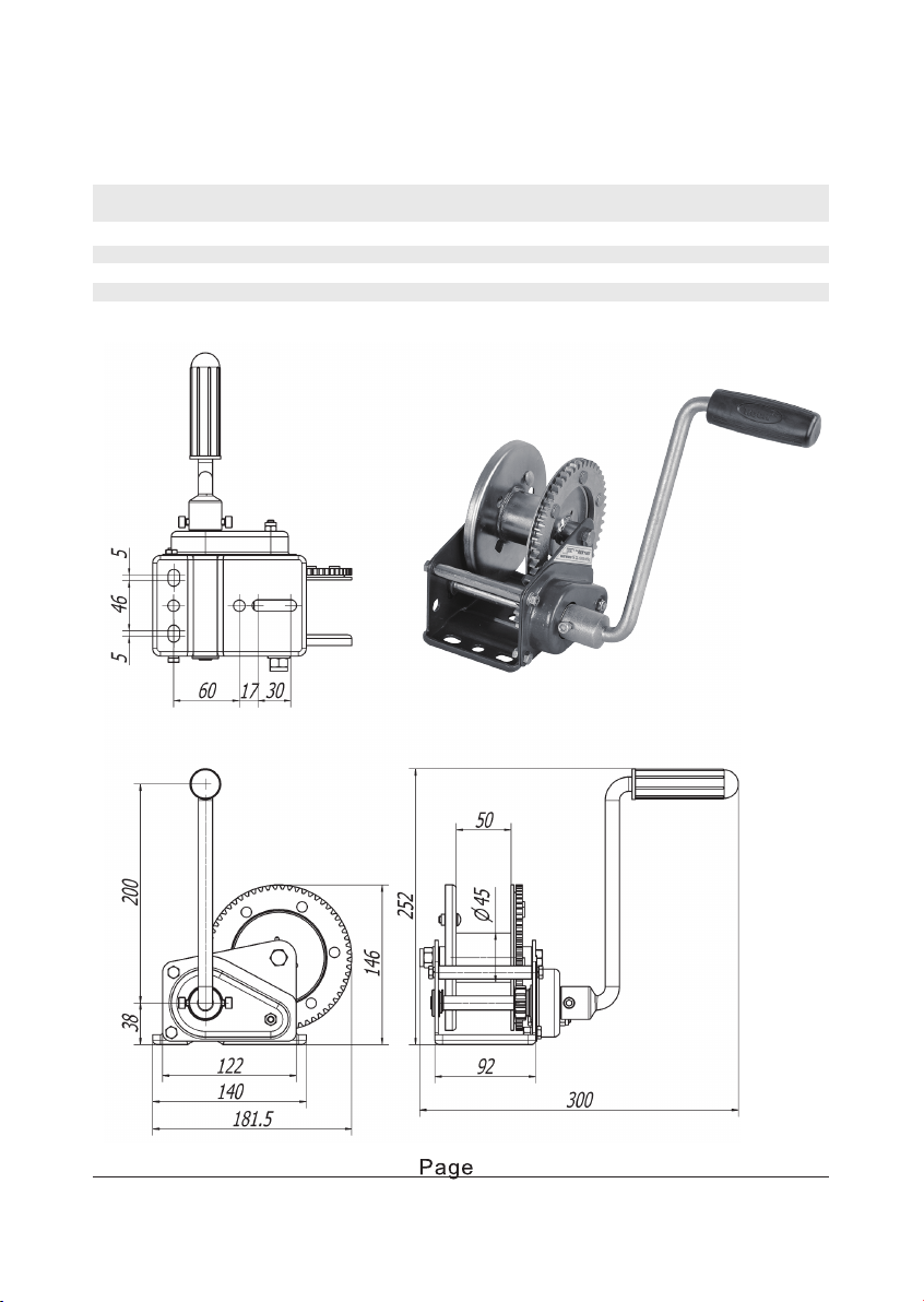
Model:RBW1000/RBW1200/RBW1500
Model Capacity Gear Drum capacity Handle N.W.
kgs lbs ratio cable belt force(N) (kgs)
RBW1000 454 1000 3.5:1 ø4.76mm×15m 1x50mm×6m <160 3.1
RBW1200 545 1200 4.3:1 ø4.76mm×15m 1x50mm×6m <160 3.3
RBW1500 681 1500 5.1:1 ø4.76mm×15m 1x50mm×6m <200 3.4

02
Model:RBW2000/RBW2500
Model Capacity Gear Drum capacity Handle N.W.
kgs lbs ratio cable belt force(N) (kgs)
RBW2000 908 2000 8.8:1 ø6.35mm×15m 1.2×50mm×6m <200 6.8
RBW2500 1135 2500 11:1 ø6.35mm×15m 1.2×60mm×6.5m <200 6.9

03
Model:RBW3500
Model Capacity Gear Drum capacity Handle N.W.
kgs lbs ratio cable belt force(N) (kgs)
RBW3500 1588 3500 18.4:1 ø7mm×15m 1.2×60mm×6.5m <200 8.15

04
Model:RBW1000F/RBW1200F/RBW1300F/RBW1500F
Free Spooling
Model Capacity Gear Drum capacity Handle N.W.
kgs lbs ratio cable belt force(N) (kgs)
RBW1000F 454 1000 3.5:1 ø4.76mm×15m 1×50mm×4.5m <160 3.1
RBW1200F 545 1200 4.3:1 ø4.76mm×15m 1×50mm×4.5m <160 3.4
RBW1300F 590 1300 5.1:1 ø4.76mm×15m 1×50mm×4.5m <200 3.4
RBW1500F 681 1500 5.1:1 ø4.76mm×15m 1×50mm×4.5m <200 3.4

05
Model:RBW2000F/RBW2500F
Free Spooling
Model Capacity Gear Drum capacity Handle N.W.
kgs lbs ratio cable belt force(N) (kgs)
RBW2000F 908 2000 8.8:1 ø6.35mm×15m 1.2×50mm×8m <200 6.8
RBW2500F 1135 2500 11:1 ø6.35mm×15m 1.2×50mm×8m <200 6.9

06
Model:RBW3500F
Free Spooling
Model Capacity Gear Drum capacity Handle N.W.
kgs lbs ratio cable belt force(N) (kgs)
RBW3500F 1588 3500 18.4:1 ø7mm×15m 1.2×60mm×6.5m <200 8.15

07
Model:RWS2000
Three Height Settings
Model Capacity Gear Drum capacity Handle N.W.
kgs lbs ratio cable belt force(N) (kgs)
RWS2000 908 2000 8.8:1 ø6.35mm×15m 1.2×50mm×8m <200 6.8
4.5

08
Model:RWC1200
Model:RSS2000
Model Capacity N.W. Inner carton Outer carton pcs/ G.W.
kgs lbs (kgs) (cm) (cm) carton (kgs)
RWC1200 545 1200 4.4 19.5×15×14 41×31×28 8 38
Model Capacity N.W. Inner carton Outer carton pcs/ G.W.
kgs lbs (kgs) (cm) (cm) carton (kgs)
RSS2000 908 2000 5.1 20.5×13.5×24.5 63×26×28.5 6 33
Separate Stand for Winch
Winch Console

09
SAFETY WARNING AND PRECAUTION
1. KEEP WORK AREA CLEAN AND DRY
Cluttered, damp or wet areas invite injuries.
2. KEEP CHILDREN AWAY FROM W ORK AREA
Do not allow children to handle this winch.
3. DO NOT USE THIS W INCH IF UNDER THE INFLUENCE OF ALCOHOL
OR DRUGS
Read warning labe ls on th e winch to de te rmine if yo ur ju d gemen t o f
re flexe s a re imp a ire d w hile taking drugs. If the re is an y dou bt, do n ot
attempt to use this winch.
4. USE EYE AND HAND PROTECTION
Wear safety impact eyeglasses and heavy duty work gloves when using
this winch.
5. DRESS SAFELY
Do not wear loose clothing or jewelry, as they can become caught in
moving parts. Wear a protective hair covering to prevent long hair from
be coming ca u gh t in movin g p arts. If w ea ring a long sle eve sh irt, roll
sleeves up above elbows.
6. DO NOT OVERREACH
Keep proper footing and balance at all times to pre ven t tripping , falling,
back injury, etc.
7. STAY ALERT
Watch what you are doing at all times. Use common sense. Do not use
this winch when you are tired.
8. CHECK FOR DAMAGED PARTS
Before using this winch, carefully check that it will operate properly and
perform its intended function. Check for damaged parts an d any other
conditions that may affect the operation of this winch. Replace or repair
damaged or worn parts immediately.
9. REPLACEMENT PARTS AND ACCESSORIES
When servicing, use only identical parts. Only use accessories intended
for use with this winch.

10
Fo r yo u r safety, se rvi ce a n d ma inten a nce sh o ul d b e pe rfo rmed
regularly by a qualified technician.
WARNING:
The warnings, precautions and instructions discussed in this Manual
cannot cover all possible conditions and situations that may occur.
It must be understood by the operator that common sense and caution
ar e fac tor s w hich cannot be built into this produc t, but m us t be
supplie d by the oper ator.
10.MAINTENANCE

11
SPECIAL WARNINGS AND PRECAUTIONS
1. C A UTION : Ne ver excee d the maximu m loa d cap acity sp e cifie d o n
pa g e 2 - 8 fo r e ach mo d el.
2. A U TOMATIC MEC HA N IC AL B R AK E R EQUIR EMEN T
Th e minimum tra ctive force (pulling load) required for a proper bra king
fu n ction o n th e winch is 55 lbs (25 kgs). W ith ou t th is min imu m load ,
th e b ra king fu nction will no t take p lace .
3. AVOID SIDEWAYS C A BLE SLIP
Th e ca b le u nd er a lo ad sh ou ld
on ly be w ou n d on to th e dru m to
su ch an e xte nt th at a min i mum
space of 2 times the cable diameter
remains on the d rum flang e(Fig.1).
W inch ove rload in g an d a sidewa y
ca b le slip w ill he re be a voide d.
4. A LWAYS LEAVE AT LEA ST 5 W R A PS OF TH E C AB LE (OR BELT)
5. D O N OT OIL OR GR EASE TH E B RA K E MECH A NISM
Oil or grea se w ill make th e w inch red uce o r lose b ra ke fu nction .
2timesthecable
diameter
Fig .1
ON THE DRUM
Failure to do so may break cable 5 wraps
connection to drum and may
result in serious accident.
(see fig.2)
Fig .2

12
6. ALWAYS U SE PR O PER C O UPLING S W HEN C O NN EC TIN G TH E
W IN CH CA BLE HO O K TO A LO A D.
7. MA KE SU RE THE W INC H B ASE IS PR O PERLY BO LTED TO A
STR U C TU R E (O R VEH IC LE)THAT C AN HO LD W INC H A ND W INC H
LO A D
Failure to bolt down the winch properly can result in personal injury
and/or property damage.
8. DO NO T USE ANY ATTACHMENTS to extend the length of the winch
ca b le .
9. AFTER MO VING AN O B J EC T W ITH TH E WINC H , SEC U RE THE
O BJ EC T. DO N O T R ELY O N TH E W INC H TO H O LD A N O B JEC T
FO R A N EXTEN DED PER IO D O F TIME.
10 .W HEN LO A DIN G A B O AT O NTO A TR AILER wi th o ut kee l o r si d e
hu l l ro l le rs, ma ke su re the tra i le r is su bme rg ed i n the w ate r w hen
th e b oa t is loa d ed b y th e w in ch. Atte mp ti n g to d rag the b o at onto
th e tra il e r wh il e o n la n d ca n cau se th e wi n ch fai l ure an d p ossi b le
pe rso nal i nj u ry a n d pro pe rty d ama ge .
11 .DO NO T A PPLY A LO A D to th e wi n ch w hen th e wi n ch cab l e is ful l y
exten de d . The cable anchor on th e wi n ch i s n o t ca p ab l e of hol d in g
th e ma ximum rate d lo ad ca pa city.
12 .STAND B AC K
Stay out of the direct line that the winch cable is pulling.In the event
th e w in ch ca bl e sli ps or bre aks, it wi l l “w hi p l ash ” a lo n g thi s l in e .

13
CR A NK H AN D LE A SSEMB LY:
In se rt th e h exag o n so cke t o f the C ran k Ha n dle on to th e h exag on e nd
of th e Main Drive Axle. (Fig .3) Scre w tig h tly u sing the en close d screw
(n u t) and H e x-ke y.(Fig.4 )
FITTIN G THE C A BLE:
In se rt th e Ste e l Ca b le (not included, supplied to special order) th rou gh
th e sq ua re ho le fro m inside to ou tsid e . Thru st th e Ste el Cable into one
side o f the C able An ch o r (Fig .5). In se rt the ca b le end into the o th e r side
of th e C ab le An ch o r lea ving a larg e loo p o utside(Fig.6).
ASSEMBLY
Fig .3 Fig .4
Cable Anchor
Tigh ten th e Nut slig htly.Pu ll an d
re d uce th e lo o p do w n to the Cable
Anchor . (See Fig.7)
Fig .5 Fig .6
Fig .7

14
Th e ca b le mu st be pressed b y a C a bl e Cl a mp i n to the e ye of Spri ng
La tch H oo k with a G ro mme t Th i mb l e on . (Fig .9 )
Tighten the Nut with a turning
to rq u e o f 5-10 N M (fi g.8 ).
Replace the Cable Anchor each
time when the Cable is replaced.
FITTIN G B ELT w ith Fitting B ar
Th e w in ch i s desig n ed to fi t a
be l t as wel l as a cab le .Pu sh th e
Be l t fittin g Ba r, th ro u gh th e b el t
lo o p in the d i re cti on of the a rro w
(Fi g .10 )
Spring Latch Hook Grommet Thimble Cable Clamp
Cable
Fig .8
Fig .9
Fig .10
Belt Fitting Bar
Se cu re th e Be l t Fi tti ng Ba r wi th
a scre w, a spri ng w a sh e r an d a
fl a t wa sh e r.(Fi g .11)
Fig .11

15
WA RN ING
Th e b elt b re a king stra in mu st b e at lea st 3 times the p ulling capacity and
7 time s th e liftin g cap a city of the w in ch.
FITTIN G POSITION OR D IRECTION OF OPER ATION
Fittin g th e winch w ith th e flee t
an g le no mo re th an 4 ° (Fig.12)
≤4°
Fig .12

16
OPERATION
1. Lifting, Pulling
2. Stopping
3. Lowe ring, C able r e le asing
Tu rn th e Cran k Han dle clockwise .
Th e loa d ca n be stop p ed in an y position simp ly by le ttin g go o ff the
Cra nk H a nd le .
Tu rn th e Cran k Han dle anti-clo ckw ise to low er the load o r releasin g
th e ca b le .The a u to ma tic bra ke ca n pre ve nt the C ra n k Ha n dle from
kickin g b ack.
WA RN ING:
Th e b ra ke fu nction w ill only be a ctiva te d b y a minimum load of 25kgs.
Do n o t o il o r gre ase the b ra ke me cha nism. (Fig .13)
Do not oil or grease
the brak e mechanism
Fig .13
Crank Handle
Assembly

17
MODEL:RBW1000F, RBW1200F, RBW1500F, RBW2000F,
RBW2500F,RBW3500F
OPERATION
1. Lifting, Pulling
2. Stopping
3. Lowe ring
WA RN ING:
4. Fr ee Spool
WA RN ING:
5. Stop using Free Spool function
Turn the Crank Handle(Handle Assembly) clockwise.
The load can be stopped in any position simply by letting go off the
Crank Handle.
Tu rn th e Cran k Han dle anti-clo ckw ise to low er the load . Th e a uto
matic brake can prevent the Crank Handle from kicking back.
The brake function will only be activated by a minimum load of 25kgs.
Do not oil or grease the brake mechanism.
W ith load on the cable(or belt), you can not use this FREE
SPOOL fun ctio n , o th e rw ise you may ge t pe rso nal injury or p ro p erty
damage.
Turn the Handle Knob back to Auto Brake position(Fig.15).
1). Take off the Crank Handle.
2). Press Handle Knob in the direction of arrow(Fig.14).
3). Turn left as indicated on the operating label. The cable drum now can be
turned freely.
Fig .14
Free Spool Position
Press
T
u
r
n
L
e
f
t
Fig .15
Auto Brake Position
Press
T
u
r
n
R
i
g
h
t

www.endurance-marine.com
This manual suits for next models
21
Table of contents
Other Endurance Winch manuals
Popular Winch manuals by other brands

Dutton-Lainson
Dutton-Lainson DL600A manual

AL-KO
AL-KO A BASIC Series Translation of the original operating instructions

Kolpin Outdoors
Kolpin Outdoors 25-3410 Assembly & owners manual

Farmi Forest
Farmi Forest JL 450 OPERATION, MAINTENANCE AND SPARE PARTS MANUAL

Shark
Shark 800-102601 Operation manual

Allied Systems
Allied Systems Allied H6G Series Service manual