EndurEnergy Systems ESP-5K HL User manual

ESP-5K HL
Residential & Commercial
ESS Manual

About this manual
This manual is intended for the ESP-5K HL Lithium Iron Phosphate (LiFePo4) Battery.
These batteries can be installed in parallel and series configurations. Please pay close
attention to the DIP switch setting, address selection and cable connections.
Statement
This product is compliant with the Best Practice Guide for Battery Storage Equipment—
Electrical Safety, version 1. It meets the mandatory requirements of Method 1 for pre-
assembled integrated battery energy storage system equipment, as well as the optional
requirements listed under points a), c), e), f), g), h), i), j), k), l), m), n), o), p), and q).
Declaration
EndurEnergy declares that the ESP-5K HL is compliant with the essential requirements
and other relevant standards of UL/CE.
Disclaimer
EndurEnergy cannot be responsible for system failure, damage, or injury resulting from
improper installation of their products. The information included in this manual is subject to
change without notice.

CONTENT
1Safety Introduction ......................................................................................................................................... 1
1.1 Important Safety Instructions....................................................................................................... 1
1.2 Warnings in this Document............................................................................................................ 1
1.3 Battery Handing Guide ....................................................................................................................2
1.4 Response to Emergency Situations ............................................................................................2
1.4.1 Leaking Batteries ....................................................................................................................2
1.4.2 Fire ...............................................................................................................................................3
1.4.3 Wet battery.................................................................................................................................3
1.4.4 Damaged Battery.....................................................................................................................3
1.5 Installers ............................................................................................................................................ 4
1.6 Disposing Batteries......................................................................................................................... 4
1.7 Contact Information ........................................................................................................................ 4
2Guidance for Disconnection of Batteries During Shipment.............................................................. 5
3Product Introduction ......................................................................................................................................6
3.1 Technical Specifications .................................................................................................................6
3.2 Indicators and Ports.........................................................................................................................7
3.2.1 Indicators ...................................................................................................................................7
3.2.2 Ports ............................................................................................................................................7
3.2.3 Communication Interface..................................................................................................... 8
3.3 Typical Battery application.............................................................................................................9
3.4 Feature................................................................................................................................................11
4Installation Prerequisites............................................................................................................................11
4.1 Installation Process ........................................................................................................................11
4.2 Installation Location ...................................................................................................................... 12
4.3 Tools.................................................................................................................................................... 12
4.4 Personal protective equipment (PPE)...................................................................................... 13
4.5 Storage............................................................................................................................................... 13
5Battery Installation.......................................................................................................................................14
5.1 Package Items .................................................................................................................................14
5.2 Before Installation..........................................................................................................................14
5.3 Battery Mounting............................................................................................................................. 15
5.3.1 Rack Mounting (R6 / R12) ....................................................................................................15
5.3.2 Enclosure Mounting - (BU10/15/20/30)...........................................................................18
5.4 Cable Connections of the Battery.............................................................................................. 21
5.4.1 Battery Grounding ................................................................................................................ 22
5.4.2 Series Connection (High Voltage application)............................................................. 23
5.4.3 Parallel Connection (Low Voltage application) ........................................................... 25
5.4.4 Communication Cables....................................................................................................... 27
5.5 Battery DIP Switch Setting ......................................................................................................... 30
6Battery Internet connectivity....................................................................................................................40

6.1 APP Connection..............................................................................................................................40
6.1.1 Configure Battery WIFI.........................................................................................................41
6.1.2 Visualize Battery Data from the App ..............................................................................43
7Commissioning .............................................................................................................................................43
7.1 Commissioning Battery................................................................................................................43
7.2 Shutting Down Battery.................................................................................................................44
8Firmware Update & Troubleshooting.....................................................................................................44

1Safety Introduction
1.1 Important Safety Instructions
This manual contains crucial instructions for the ESP-5K HL Residential and Commercial ESS
product. It is imperative to follow this manual during installation and use of the product.
While this product is designed and tested to meet international safety requirements such as UL1973,
CE, IEC 62040, and IEC 62619, it is essential to take certain precautions when installing and/or
operating any electrical and electronic equipment. Tominimize the risk of personal injury and ensure
the safe installation and operation of the product, it is crucial to thoroughly read and adhere to all
instructions, cautions, and warnings provided in this manual.
WARNING
Failure to follow the instructions or warnings in this document can result in electrical
shock, serious injury, or death. Damage to the Battery is also possible, potentially
rendering it inoperable.
High Life Risk Due to Fire or Electrocution – ONLY qualified personnel should install the
ESP-5K-HL.
1.2 Warnings in this Document
A warning indicates a potential hazard to equipment or personnel. It highlights procedures or
practices that, if not performed correctly, may result in damage to or destruction of the equipment,
other connected equipment, or personal injury.
Symbol
Description
Caution, risk of electric shock
Heavy enough may cause severe injure
Keep the battery away from open flame or ignition sources
Keep the battery away from children
Dispose of waste batteries according to local laws and regulations
Recycling
Read this manual before installation and operation
For safety reasons, it is the responsibility of installers to thoroughly review the contentsof this manual
and familiarize themselves with all warnings prior to performing the installation.

1.3 Battery Handing Guide
Please follow the guidelines below to ensure safe handling and usage of the battery pack:
⚫Use the battery pack only as directed.
⚫If the battery appears cracked, broken, damaged, or fails to operate, immediately contact
EndurEnergy hot line at 1-888-E2-ENDUR (1-888-323-6387).
⚫Do not attempt to open, disassemble, repair, tamper with, or modify the battery in any way.
⚫The battery is not suitable for users to handle independently.
⚫When transporting the battery, handle itwith care to protect the battery and its components from
damage.
⚫Avoid subjecting the battery to any strong force or impact.
⚫Do not insert foreign objects into any part of the battery pack.
⚫Refrain from using cleaning solvents to clean the battery.
⚫Never connect the battery directly to a SELV (Separated Extra-Low Voltage) circuit.
1.4 Response to Emergency Situations
While the ESP-5K HL Residential and Commercial ESS is equipped with multiple safety features to
prevent hazards caused by failures, it is important to note that EndurEnergy cannot guarantee
absolute safety in uncertain situations.
1.4.1 Leaking Batteries
In the event of electrolyte leakage from the battery pack, it is crucial to avoid contact with the
leaking liquid or gas. Electrolyte is corrosive and can cause skin irritation and chemical burns. If
you are exposed to the leaked substance, please follow these actions:
•Inhalation:
oEvacuate the contaminated area immediately.
oSeek medical attention without delay.
•Eye contact:
oRinse your eyes with flowing water for at least 15 minutes.
oSeek medical attention promptly.
•Skin contact:
oWash the affected area thoroughly with soap and water.
oSeek medical attention as soon as possible.
•Ingestion:
oIf the electrolyte is ingested, promptly induce vomiting.
oSeek immediate medical attention.

The previous instructions are provided to address potential risks associated with electrolyte
leakage. It is important to prioritize your safety and seek professional medical assistance without
delay in case of exposure to the leaked substance.
1.4.2 Fire
In the event of a fire, it is important to have an ABC or carbon dioxide extinguisher readily available.
Do not use water to extinguish the fire.
WARNING
The battery pack may catch fire when heated above 150°
If a fire breaks out where the battery is installed, please follow these actions:
•Prioritize extinguishing the fire before the battery catches fire if it is safe to do so. Use
appropriate fire extinguishing methods and equipment according to the type of fire (e.g., ABC
or carbon dioxide extinguisher). Ensure your safety and consider seeking professional
assistance if necessary.
•If the battery has already caught fire or if it is not safe to attempt extinguishing the fire,
prioritize the immediate evacuation of all individuals from the area. Follow established
emergency evacuation procedures and ensure everyone moves to a safe location. Contact
the appropriate emergency services to report the fire.
Note: The above actions are intended to address fire situations where the battery is involved.Always
prioritize personal safety and adhere to established emergency procedures.
WARNING
If the battery catches fire, it will produce poisonous gases. Do not approach.
1.4.3 Wet battery
Ifthebatterybecomes wet orsubmergedinwater,donot attempttoaccess it. Instead,pleasecontact
EndurEnergy Customer Service or reach out to your distributor for immediate technical assistance.
1.4.4 Damaged Battery
If you notice any damage to the battery, please contact EndurEnergy customer service or your
distributor for assistance as soon as possible. It is crucial to handle a damaged battery with extreme
caution, as it can be dangerous. A damaged battery is not suitable for use and may pose a risk to

people and property. If you suspect the battery is damaged, promptly return it to EndurEnergy or
your distributor.
CAUTION
A damaged battery may potentially release electrolyte or flammable gas.
1.5 Installers
It is highly recommended that the installation of the ESP-5K HL Residential and Commercial ESS is
carried out by a skilled worker or electrician. A skilled worker is defined as an individual who has
received proper training and possesses the necessary qualifications as an electrician, or has
acquired the following skills and experience:
⚫Comprehensive knowledge of the functional principles and operation of on-grid Energy Storage
systems.
⚫Understanding of the potential dangers and risks associated with the installation and use of
electrical devices, as well as familiarity with acceptable mitigation methods.
⚫Proficiency in the installation of electrical devices.
⚫Familiarity with and adherence to the instructions provided in this manual, including all safety
precautions and best practices.
1.6 Disposing Batteries
When dealing with scrap battery(-ies), it is important to comply with local laws and regulations
regarding the recycling or disposal of batteries. Please ensure that you follow the appropriate
procedures as outlined by your local authorities for recycling or disposing of Lithium Iron Phosphate
batteries.
1.7 Contact Information
For technical assistance, please use the contacts provided. Please note that the phone numbers
are available for assistance during business hours on weekdays.
Customer careline
1-888-E2-ENDUR (1-888-323-6387)
Email
support@endurenergy.com

2Guidance for Disconnection of Batteries During Shipment
⚫The ESP-5K HL is not suitable for air transport.
⚫Cartons that have been crushed, punctured, or torn in such a way that the contents are
revealed shall be set aside in an isolated area and inspected by a skilled person. If the
package is deemed to be non-shippable, the contents shall be promptly collected,
segregated, and either the consignor or consignee should be contacted.
⚫The DC circuit of the ESP-5K HL battery has been disconnected and turned off prior to
shipping.
⚫We have conducted comprehensive tests to ensure that the equipmentdistributed worldwide
is safe for shipping. These products should be handled with care and immediately inspected
if visibly damaged. If the carton is visibly damaged, please contact EndurEnergy customer
service to confirm whether the battery can be used safely or not.

3Product Introduction
3.1 Technical Specifications
Product Type
ESP-5K HL
Total Energy*
5.00 kWh
Usable Energy (DC)*
5.00 kWh
Nominal Discharge/Charge Power
3.0 kW
Peak Power (Only Discharge)
6 kW for 3s
Voltage
48~56 VDC
Constant Current
(Only Discharge)
70A
Battery Capacity
100 Ah
Maximum Charge Current
60A
Maximum Charge Voltage
57.6 VDC
Weight
45 kg
99.21 lb
Dimensions
442 x 500 x 133 mm
17.4 x 19.7 x 5.2 inch
Max. Recommended Depth of
Discharge (DOD)
90%
Operating Condition
Indoor use
Charge Temperature Range
0-50 ⁰C
32-122 ⁰F
Discharge Temperature Range
-10-50 ⁰C
14-131 ⁰F
WIFI Frequency Range
2400 MHz-2483 MHz
Humidity Limit
<60% (no condensed water)
Over Voltage Category
II
Cooling Type
Natural cooling
Case Material
Steel
Color
White
Installation
Wall Mounting/Ground Installation
IP Rating
IP 20
Protective Class
I
Max. Number of Parallel
Connections
16S/16P
Warranty
10-Year
Lifespan
> 15 years
Communication Protocols
CAN/ RS485
Protection Mode
Dual hardware protection
Battery Protection
Over-current/Over-voltage/Short circuit/ Under-
voltage/Over temperature
Safety Certificate
UL1973, UL9540a, UL9540
Hazardous Material
Classification
9
Transportation
UN 38.3
*Testing conditions based on temperature 25 ⁰C at the beginning of life.
*Total Energy/Usable Energy measured under specific conditions from ESP 0.2C CC-CV.

3.2 Indicators and Ports
3.2.1 Indicators
There are two LED indicators on the front of the battery that show its operating status.
Item
Designation
Definition
1
Run
Steady: The battery is working normally.
Blinking: Reset Button pressed, expecting Wifi
connection from App.
2
Fault
There are failures or issues with the battery. See
troubleshooting or contact EndurEnergy Tech
Support.
3.2.2 Ports
The power cable interface and the communication cable interface are shown in the
following image.

3.2.3 Communication Interface
Designation
Definition
SW 1
The DIP switch is used to select the communication mode between
CAN and RS485. Please refer to the inverter's user manual for
detailed instructions.
•For CAN Communication, set SW1 to positions 1 and 2.
•For RS485 Communication, set SW1 to positions 3 and 4.
SW 2
The communication resistance and DIP switch settings for parallel
or series connections.
DIP switch settings for the Master Battery (SW2):
•For Parallel Connection, set SW2 to positions 1 and 3.
•For Series Connection, set SW2 to positions 1, 3, and 8.
(See Section 5.5)
SW 3
Used for setting the battery address in a multiple battery system
setup. (See Section 5.5)
SW 4
Used for communication between the primary battery and the
inverter.
•Factory standard setting: position 5 only.
SW 5
Used for communication between the primary battery and the
inverter.
•Factory standard setting: position 4 only.
Reset
Used to reset the Wi-Fi or GPPS/GPS module configuration.

Inverter
Ethernet port used for communication between the primary battery
and the inverter.
M/S
Ethernet ports used for communication between batteries.
WAN
Ethernet port used for the network interface.
NOTICE
The battery is designed to work on a close loop environment for communicating with a
Solark inverter or compatible inverter (check inverter compatibility list), for open loop type
of applications we do not ensure proper operation and not encourage it. If you intend to use
the battery on an open loop application or not supported inverter, call our technical support.
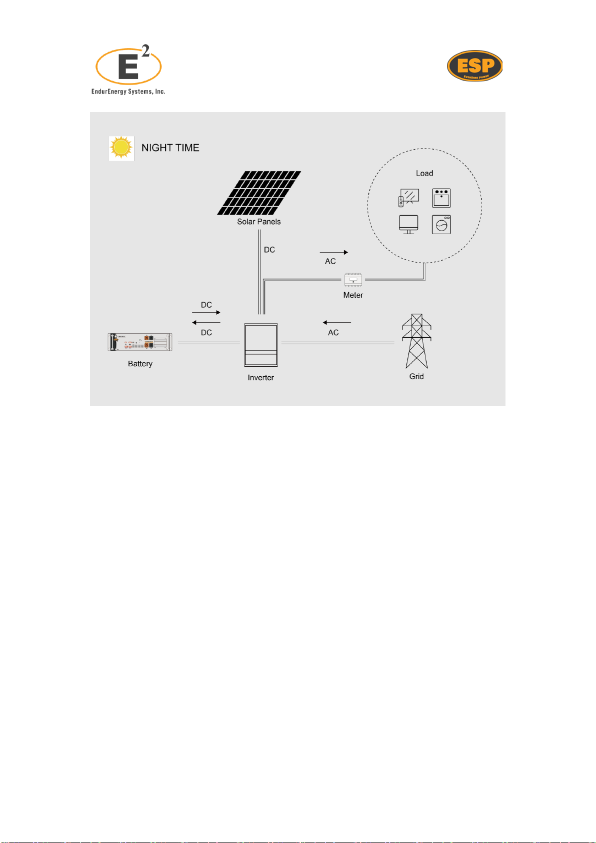
3.3 Typical Battery application

3.4 Feature
The ESP-5K HL battery has the following features:
⚫Energy storage unit: This battery is suitable for compatibility with photovoltaic
systems.
⚫Battery management system (BMS): The battery has a built-in BMS that
monitors its operation and prevents it from operating outside the design limitations.
⚫Monitor: The battery's built-in BMS is equipped with a WiFi module, allowing users
to monitor the battery's operating information on mobile phones and computers.
⚫Easy firmware update: The BMS firmware can be easily updated to the latest
version.
⚫Expandability: The battery capacity can be increased by adding another battery.
4Installation Prerequisites
4.1 Installation Process
The battery should be installed according to the following flowchart. The detailed
installation process is described in Section Battery Installation.

4.2 Installation Location
Ensure that the installation location meets the following conditions:
⚫The building is designed to withstand earthquakes as per the building code (when
applicable).
⚫It is far away from the sea to avoid saltwater and humidity.
⚫The floor is flat and level.
⚫There are no flammable or explosive materials nearby.
⚫The optimal ambient temperature is between 15°C and 30°C.
⚫The temperature and humidity remain at a constant level.
⚫There is minimal dust and dirt in the area.
⚫There are no corrosive gases present, including ammonia and acid vapor.
⚫The battery and racks are rated IP20, indicating that they are suitable for indoor
use, if required to be placed outside it will require an enclosure or cabinet.
If the ambient temperature is outside the operating range, the battery will protect itself by
shutting down. The optimal operating temperature for the batteryis 15°C to 30°C. Frequent
exposure to severe operating conditions would negatively affect the performance and
lifespan of the battery.
4.3 Tools
To install the battery pack, the following tools are required:
Flat-head &
Phillips
Screwdriver
Torque wrench
Cable crimper
Wire clamp
Voltmeter
Measuring tape
Drill
Bubble Level

To ensure the safety of the operator and installer, please select and use suitable tools
and measuring instruments that are certified for precision and accuracy.
4.4 Personal protective equipment (PPE)
When handling the battery, the following safety gear should be worn. Installers must
comply with the relevant requirements of UL1973, IEC 62040, and IEC 62619, or
applicable domestic legislation and other relevant international standards.
Insulated gloves
Safety goggles
Dielectric Safety shoes
4.5 Storage
If the battery is not going to be installed immediately and needs to be stored for a long
period, please choose an appropriate location for storage. Follow these instructions for
storage:
⚫Do not stack more than four battery boxes.
⚫The recommended storage temperature for the battery is in the range of -20°C to 30°C.
⚫Avoid exposing the battery to water.
⚫If the battery needs to be stored for over 3 months, it will discharge at a minimum rate
and the capacity may degrade depending on the storage time.
⚫If the battery is stored for over 6 months, it is recommended to connect the battery
with the inverter and commission the system.
⚫The battery boxes should be stored upright as shown in the following figure and should
not be stacked upside down.

5Battery Installation
5.1 Package Items
You will receive one packing carton containing the batteries. The items included are
summarized as follows:
1 x ESP-5K HL
1 x User Manual
1 x Warranty Letter
1 x Communication Cable
1 x Power Cables
1 x Grounding Wire
Note: Product accessories are customized according to customer needs. This list
represents only the standard accessories. Endur does not provide cables for all situations,
for special projects ask sales team.
5.2 Before Installation
There are a few things to check before installing the battery to ensure that it is free of
defects.
Check the battery voltage using the following instructions:

⚫Press and hold the panel button for 4 seconds and release it when two indicators
turn on.
⚫Measure the voltage at the terminal interface using a voltmeter. If the voltage is
lower than 48V, do not use the battery and contact customer service.
⚫Turn off the battery after checking voltage.
5.3 Battery Mounting
TheESP-5K-HLis designed as a rack mount type battery, this adds flexibility on installation
and modularity for different configurations. We offer different rack and enclosure solutions
for our batteries, see instructions below.
5.3.1 Rack Mounting (R6 / R12)
1. Place the Rack in the location desired (refer to the details about the installation
location described in Chapter 4.2).The enclosure should be moved close to its
installation location inside its shipping container before it is unpacked. The
enclosure must be installed in a structurally sound area with a level floor that is
able to bear the weight of the rack + the intended number of batteries to be installed
inside.
CAUTION

2. Adjust leveler feet (if included), lower each leveler unit it reaches the floor, make
sure each leveler contacts the floor solidly. After lowering each leveler, use the
carpenter's level / bubble level to confirm thatthe rack is level. Adjust levelers as
needed to get level.
3. In order to secure the rack to the building structure for stability, attach the provided
brackets to the wall or to the floor (depending on the rack model) using adequate
screws. Verify foundation for seismic installations.
4. Slide in each battery into the horizontal brackets of the rack, each battery must be
spaced out vertically 1/3 U (0.583” / 14.82 mm) to ensure heating dissipation. Use
M6 screws to secure the batteries in place to cage nuts, max torque of 8.7 lb*ft. If
Rack does not have cage nuts, use the appropriate screws to fix into the predrilled
holes.
Table of contents
Popular Batteries Pack manuals by other brands

C&D Technologies
C&D Technologies LIBERTY 1000 Series Installation and operating instructions

Huawei
Huawei ESS-240V12-9AhBPVBA Series Quick installation guide

enouvation
enouvation enPower ENBKP-V2 Guide and User Manual

RedEarth
RedEarth BlackMax installation manual

Growatt
Growatt ARK 2.5H-A1 Quick installation manual

Insignia
Insignia NS-MB10400 Quick setup guide


